UVL Series™Models
General Function: Electrohydraulic, power up/gravity down operation, power in/out
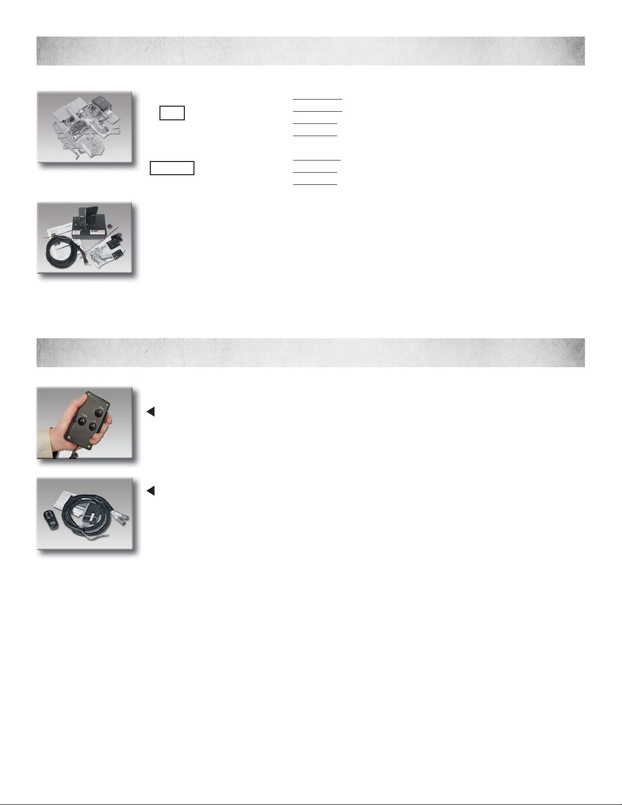
Control: hand-held control box, and optional remote
Hydraulic: Pressure Max. 3,249 psi, Fluid is Univis HVI 26, oil reservoir is .25 gal
Construction: Aluminum Housing with Steel inner structure with powder coat nish
Operating Temperature: -7ºC to 65ºC
Power Supply: 12VDC Current Consumption: Max. 120A (12V)
NUVL603C
(NUVL603C Shown)
NUVL855C
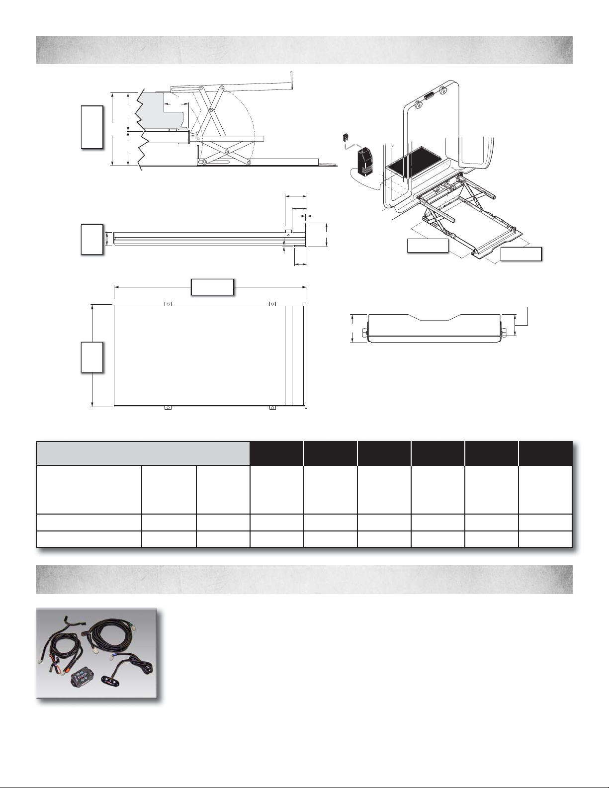
NHTSA Compliant Usable Platform: 31” x 48”
NHTSA Compliant Usable Platform: 30” x 53”
To ensure proper installation of the Under Vehicle Lift (“UVL”), BraunAbility maintains the following recommendations regerding after-
market drive line and suspension modications that may be required to meet the specications for ground and drive shaft clearances.
Once the installation of the UVL is complete, the installer shall ensure that the vehicle drive shaft cannot come in contact with the lift. The
best way to check that the proper clearance is achieved is to raise the vehicle using a hoist capable of raising the vehicle while suciently
supporting the chassis. This will allow the rear suspension to relax to its maximum extension before measuring the clearance. Note:
The drive shaft must clear the lift with full suspension travel. 1 inch of clearance between the top of the lift and the drive shaft will allow
proper operation of the vehicle under most normal driving conditions. BraunAbility does not recommend the use of axle limiting devices,
as their use may degrade the vehicle’s safety.
Upon completing installation of the UVL, the installer shall ensure that acceptable clearance is maintained between the lift and pave-
ment. In making this determination, the installer must take into consideration that the vehicle may be loaded to maximum capacity
during regular driving. BraunAbility recommends a minimum of ve (5) inches of clearance be maintained during all driving condi-
tions. After-market drive line kits and/or suspension modications can assist in maximizing ground clearance if properly utilized. In
some cases, after-market exhaust accessories can allow the UVL to be mounted closer to the vehicle frame, thereby increasing clear-
ance. Increasing the manufacturer’s wheel and tire size may increase ground clearance, but may void the vehicle’s warranty, negatively
eect its handling and render inaccurate the readings of the vehicle’s odometer and speedometer.
W
ARNING
81823
PushT-handlein fully and
manuallymove platform in
andout to engage platform
lockbefore driving vehicle.
Failureto lock platform may
resultin unintended platform
deployment. Unintended
platformdeployment may
resultin serious bodily injury
and/orproperty damage.
Donot remove!
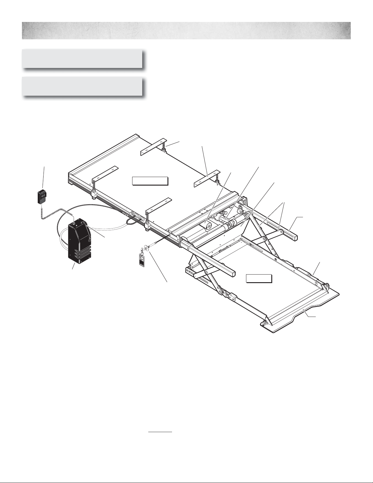
Lift Housing
Pump
Module Platform
Chain Drive
Motor
Hydraulic
Cylinder
Hand
Pump
(inside
cover)
Rolling
Horizontal
Arms
Roll Stop
Actuator
Outboard
Roll Stop
Hand-Held
Attendant's
Control Box
Platform Cable-
activated Manual
Release System
Lift Mounting
Brackets (4)
Lifting Arms
Inboard Barrier