BREN 515 User manual

BREN, Inc.BREN, Inc.
Users Manual
for the
Models 515 and 525
Stencil & Sign Cutter
Users Manual
for the
Models 515 and 525
Stencil & Sign Cutter
BREN, Inc.
8401 Covington Rd.
College Grove, TN 37046
BREN, Inc.
8401 Covington Rd.
College Grove, TN 37046

2
Chapter 1
General Descriptions
1.1 Introduction
1.2 Installation
1.3 Daily Maintenance and Care
1.4 Stand Assembly
1.1 Introduction
This manual briefly explains how to use the BREN Model 515 & 525 for cutting
applications. Drawings, illustrations and tables are provided to enable you to effectively use
the Pro-Series Cutting Plotter within a short period.
This chapter provides instructions on the installation, daily care and precautions to observe
during use.
1.2 Installation
Notes on Installation
Avoid use or storage of the cutter in places subject to direct sunlight or the direct draft
from air-conditioning systems.
Avoid locations that are extremely dusty or humid.
Prior to cutting, ensure that no obstacles are placed in the vicinity of the carriage or
material. Impeded movement of the carriage or material may prevent accurate cutting.
To prevent malfunctions of the cutter’s sensors, position the cutter at least one meter
away from electric lights, and any other sources of indoor illumination.
ØØCaution
Lubrication of the mechanisms is not required and will result in cutter malfunctions.
To avoid scratching the cutting pad, ensure that the Blade is properly extended.
While the cutter is operating, do not touch the moving parts.
When manually moving the carriage to load material, be sure to do so slowly.
1.3 Maintenance
Daily Maintenance
During the course of daily cutter operation, be sure to observe the following precautions
Never lubricate the mechanisms of the cutter.
If the cutter’s casing becomes dirty, wipe the soiled areas using a dry cloth or a cloth that
has been moistened in a neutral detergent diluted with water.
Never use thinner, benzine, alcohol, or similar solvents; they can damage the finish.
If the cutter becomes dirty, wipe soiled areas using a dry cloth or use a cloth that has
been moistened in alcohol or in a neutral detergent diluted with water.
Never use benzine, thinner, or similar solvents to clean the sensors.

3
1.4 Stand Assembly
Stand for Models 515 and 525
Tools Required: Slotted Screwdriver, 7/16” Hex Wrench or adjustable Wrench
Note: Shipped with top plates and Casters pre-mounted.
¼-20 X 1½” Truss-Head Screws,
4 each. Insert through leg and
panel and secure with lockwasher
and hex nut.
Front roller has no spring and
mounts through holes in wings.
Attach with Cap Nuts on ends.
Rear Roller has Spring Brake for suspended rolls of material. This
roller drops into slot in rear of wing. When spring is on the Right side
the Brake is engaged. When Spring is on the left side the roller spins
free for supporting material on the cradle.
Cradle style supports material rolls on top of the
two (2) Rollers. When using cradle support, put
the spring on the rear roller on the Left side to
disengage the brake for free roll movement.
Suspended style supports material roll by
inserting the rear roller through the material core.
When suspending a roll use the Brake by locating
the Spring side of the roller on the right (as you
face the front of the stand).
Mounting plates are pre-attached to the
legs with ¼-20 x ½” machine screws.
Use slots in plates to mount cutter.
Parts List
2 ea. Legs with Wings
1 ea. Front Panel
4 ea. ¼-20 X 1½” Truss Head
Machine Screw.
4 ea. ¼” lock washer
4 ea. ¼” hex nuts
1 ea. Non-Brake Roller
1 ea. Brake Roller
2 ea. ¼” Cap Nutas
4 ea. Casters, (2) Brake and (2)
non-Brake pre-attached.
2 ea. Mounting Plates pre-
attached.
4 ea. 6mm x 12mm Screws for
attaching Cutter.
Casters are pre-installed but should
be checked and tightened if
necessary.
Use 4 ea. 6mm x 12mm
screws up through slots
andintobaseofcutter.

4
STAND ASSEMBLY for the Model 515/525 Pro-Series Stand
The Pro-Series Stand consists of two (2) Legs, a Front Panel, and two (2) Rollers to hold material rolls. Assembly is a
simple matter of joining the two legs by putting screws (¼-20 x 1½” Truss Head Machine Screws) through pre-drilled
holes in each leg and through matching holes in the front panel, then securing each screw with a lockwasher and a hex
nut. One Roller is provided without a Brake System (no spring), this roller installs into pre-drilled holes in the rear
“wings” which protrude from the rear of each leg. (See Diagram). The rear-most roller is provided with a Brake
System (Tension Spring on one side) which can be engaged or dis-engaged by simply locating the spring on the left or
right of the cart, (flipping the roller over and dropping it into the provided slot).
1. Select one of the legs and note the marking on the upper mounting plate (either LEFT or RIGHT). The marking
indicates on which side of the stand to put the leg, (either Left Side or Right Side as you face the short bottom arm of
the leg). NOTE: The “Wing” which protrudes toward the rear of each leg is always mounted on the “Outside” of the
leg, (i.e. the left leg has the wing on the left side).
2. From the package of fasteners, select one of the ¼-20 x 1½” machine screws and insert it through one hole in the
side of the leg and through the matching hole (top or bottom) in the front panel. The front panel mounts between the
two legs and is attached by four long screws running through pre-drilled holes in the legs. (See Layout) The label on
the inside of the panel faces the rear of the stand and is not visible from the front side of the cart after assembly.
Flanges on the front panel face to the rear. Insert each of the four (4) long screws and install a lockwasher and hex nut
on each (inside the front panel) DO NOT TIGHTEN THE SCREWS AT THIS TIME! It is necessary for the leg-to-
panel joints to be loose so that you can insert the Front Roller through the pre-drilled holes in the wings, which protrude
from the rear of each leg.
3. The Front Roller does not have a Tension Spring and is provided with a threaded shaft protruding from each end.
(See Diagram). Each end of the Front Roller is inserted through one of the holes in the leg wings, one on each side,
then the roller is secured by threading a “Cap Nut” (see parts diagram) onto each threaded shaft and snugging it against
the side of the leg wing. Once the Front Roller is installed through the leg wings, you may place the legs in an upright
position on a flat surface (either floor or table) and tighten the four (4) long screws which secure the front panel to the
legs.
4. Check that the casters are snuggly threaded into the legs, note that the front casters have brakes to secure the stand in
place. Install the Rear Roller (remaining roller with a spring) into the slots on the rear of each wing , simply lower the
roller into the slots with the Spring located on the Right Side to engage the brake or the Spring located on the Left Side
to release the break.
5. The Brake should be Engaged if you Suspend a material roll from the single rear roller, this will prevent the free
unrolling of material due to the natural tendency of a roll of material to “unwind”. BREN Stencil Material is commonly
suspended from a single roll to prevent having to bend the material backward to achieve a “feed loop”.
6. When running most thin Vinyl and Masking Materials, it is usually not necessary to suspend the rolls but rather to
“Cradle” the rolls by placing them on top of the two rollers so that the roll is supported or cradled by both rollers. When
material is cradled you will usually not require the Brake and will simply flip the rear roller over so that the Spring is
located on the Left side of the stand. (Left side as you face the front of the Stand)
7. Mount the cutter on the stand by locating the cutter on the mounting plates so that the slotted holes in the mounting
plates align with threaded holes in the bottom of the cutter. Using the four 6mm x 12mm pan head screws, attach the
cutter to the plates by running a screw up through the slot in the plate and into a threaded hole in the cutter. Use all four
screws as this will ensure that the cutter is properly aligned with the rollers and is secure to the stand.
8. USE CAUTION WHEN ROLLING THE STAND TO PREVENT IT FROM TIPPING OVER.
9. Load material rolls so that the material feeds from the top of the roll and directly into the back of the cutter, (see
diagram). Material rolls can be loaded to ride on both rollers in a cradle or can be suspended from the single rear roller
by inserting the rear roller through the core of the roll and allowing the material to hang on and be suspended by the
single rear roller. The rear roller is designed to easily lift up and drop into the two slots located on the rear of the wings.
This allows for easy removal and replacement of the rear roller.

5
Chapter 2
Descriptions of parts and functions
2.1 Nomenclature
2.2 Control panel
2.3 Selection of Functional Menu
2.1 Nomenclature
(1) Tool carriage : Moves the Blade or Pen across the material during cutting or plotting
(2) Tool holder : Holds the Blade Holder or Plotter Pen on the carriage
(3) Pinch rollers : Push the cutting or plotting material against the grit roll.
(4) Grit rollers : Feed the material forward or reverse during cutting or plotting.
(5) Cutting platen : Position the material on the platen for cutting or plotting.
(6) Roller Knob: Raise or lower the pinch rollers to enable the material to be loaded.
(7) Control panel : Use to set and use the machine’s various functions.
(8) Stand : Holds the machine and material rolls while cutting.
(9) Cutting Pad: Teflon strip on which the Blade rides for back-up while cutting.
(10) Plotting Pad: Felt strip in front of Teflon strip for back-up to plotter pen.
(11) Align Guides: Vertical white marks to aid in material alignment.
(12) Labels: Mark the location for the Pinch Rollers to be correctly placed.
9
10
11
12
6
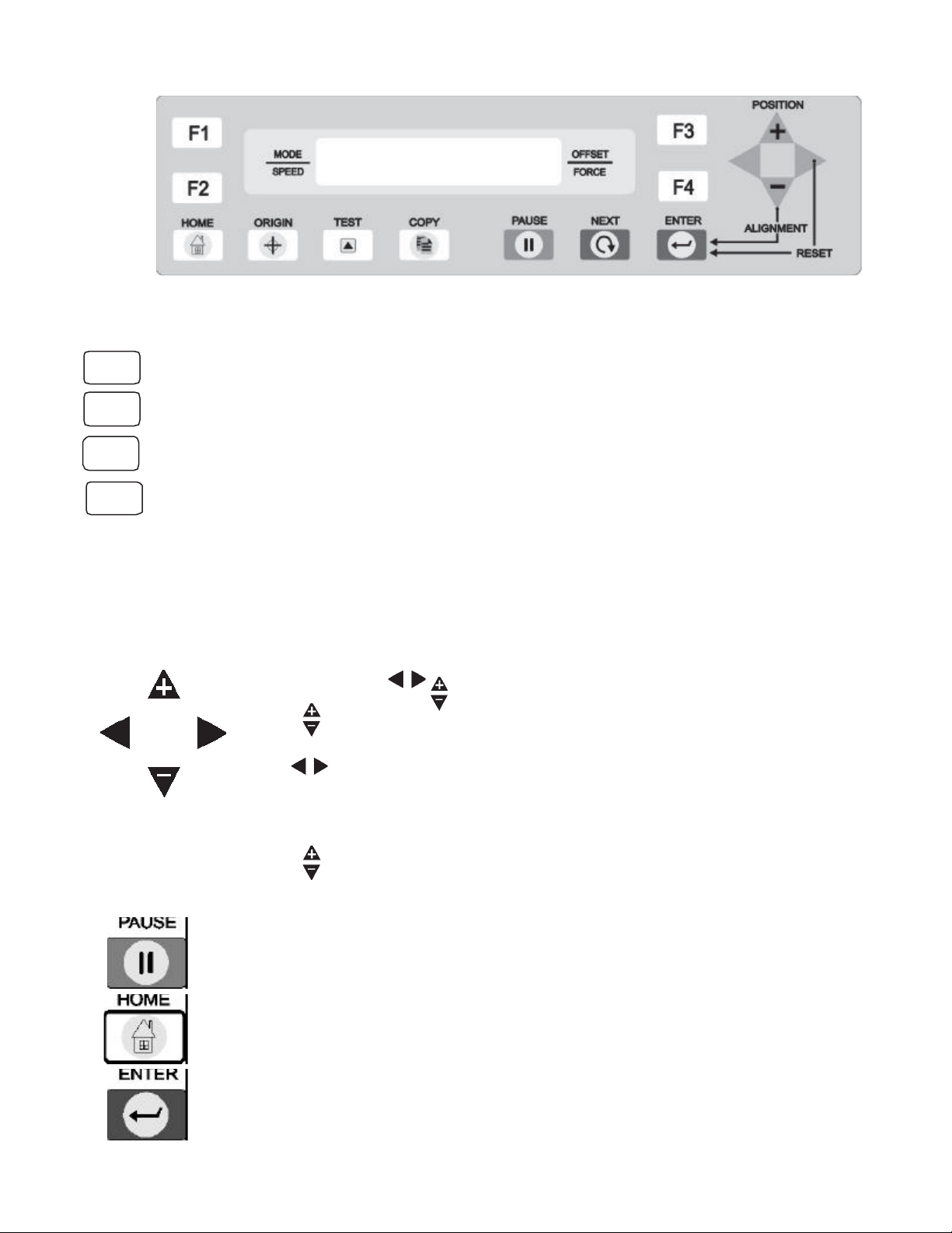
2.2 Control Panel
Selection keys
Press the F1 key to select USER MODE
Press the F2 key to change the cutting speed
Press the F3 key to change the Offset Value
Press the F4 key to change the Pen Force
When you press individual keys F2, F3, F4, the corresponding Values on the LCD will
blink. By pressing the direction keys with + or – you can change the values up or down.
Direction keys
Position
Use 4 keys , , to move the tool carriage to the desired location
keys move the material forward or backward.
keys move the carriage to the Left or to the Right.
For quick movement of the carriage, press and hold a direction key.
keys are used to increase or decrease default value on the menu.
Function Keys
Press this key to stop the cutting or plotting operation temporarily.
When you press PAUSE again, the cutting or plotting operation will continue.
Press this key to return the display to the cut-mode menu.
After setting a new value, press ENTER to register the same in memory.
F1
F2
F3
F4

7
Function Keys (cont.)
Press this key to set a new origin for cutting to begin.
Press this key to perform a Test Cut using the presently set values.
Press this key until the desired menu appears on screen.
Press this key to repeat the last completed cut or plot.
2.3 Functional Menu of Keys
8
Chapter 3
CUTTER BLADES, HOLDERS AND PENS
3.1 The Cutter Blade Installing and Replacing
3.2 Adjusting the Blade Length
3.3 Attaching the Cutting Pen
3.1 Cutter Blade Replacing
Warning : To avoid injury, handle the cutter blades carefully.
CUTTER BLADE TYPES
PURPOSE BLADE NO OFFSET HOLDER NO REMARKS
General Purpose 45DBN 0.25 Standard For most Stencil and Decal materials
Thick Material 60DBN 0.50 Standard For very Thick and some tough materials
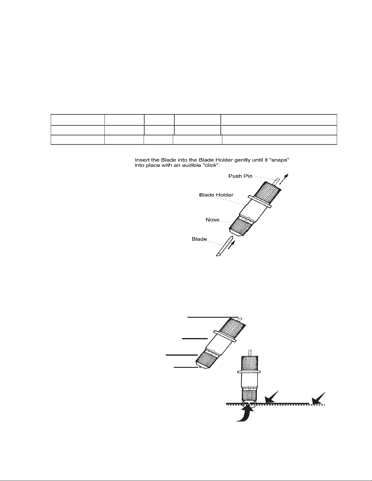
3.2 Adjusting the Blade Length
Caution : Make sure to adjust the blade length correctly. If the blade length is too long,
you may cut through the backing sheet of vinyl and damage the cutting platen of the cutter.
Obtaining the Correct Blade Length
If the material thickness cannot be accurately determined, adjust the blade length by gradually
extending until only traces of the blade appear on the backing sheet when a cutting test is executed.
For more information about the cutting test, see Section 4.5, “Running a Cutting Test.”
(1) To REDUCE the blade
extension, screw the Nose
counter-clockwise (out away
from the holder).
(2) To INCREASE the blade
extension, screw the Nose
clockwise (in toward the holder).
Holder
Nose
Push Pin
Blade Tip
Material Backing
Blade Tip
9
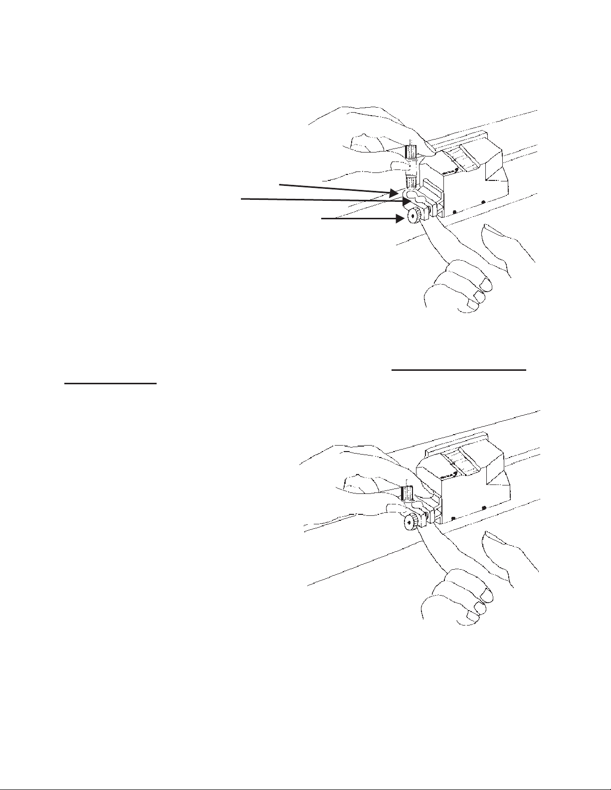
3.3 Attaching the Tool Holder with Blade
Warning! The tip of the cutter blade is sharp. When handling the cutting tool be careful.
(1) Loosen the Tool Holder screw. While supporting the tool holder upward by finger, push the
cutting pen all the way into the holder until the flange hits the stop. USE REAR HOLE for the
CUTTING TOOL, (the front hole is for the Plotter Pen Only).
(2) When the tool is fully seated, tighten the holding screw. Snug the screw finger tight only.
Remember that the REAR hole is for the Knife and the FRONT hole is for the Pen.
Holder Screw
Rear Hole for Cutting Tool
Front Hole for Pen
Tool is fully seated when Flange on
Holder or on Pen contacts the carriage.

10
Chapter 4
PREPARING TO USE THE CUTTER
4.1 Turning on the Cutter
4.2 Loading the Material
4.3 Setting the Cutting Mode
4.4 Setting the Speed, Offset and Pen Force
4.5 Running the Cutting Test
4.6 Setting the Acceleration
4.7 Setting the Scale
4.8 Setting the Measurement Unit
4.9 Axis Alignment
4.10 Setting the Cut-angle
4.11 The Copy Function
4.12 Manual Material Alignment
4.13 Over Cutting
4.1 Turning On the Cutter
Connecting the Cutter to a Power Supply
(1) Make sure that the cutter is turned off.
(2) Connect the cutter to a computer with connecting cable (either RS-232C serial cable or
the provided parallel cable)
(3) Connect one end of the power cord provided to an electrical outlet of the rated supply
voltage, connect the other end to the cutter’s AC line inlet, (located on the left side).
(4) Turn on the cutter with the power switch located on the left side next to the AC inlet.
1 Parallel Interface Connector
2 Serial Interface Connector
3 Power Switch
4 AC Line Inlet
5 BREN Mobile Stand (see page 2 for stand assembly)
6 Pinch Lever Handle
11
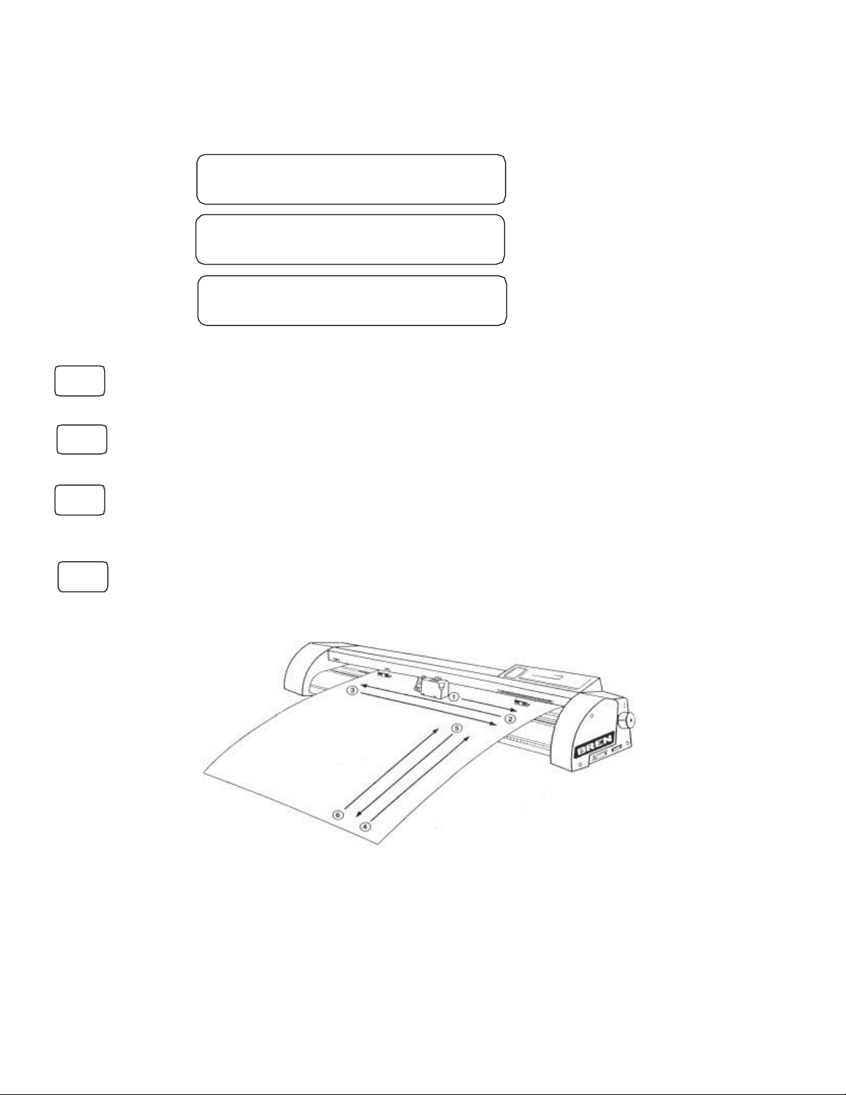
(1) When power is applied, the cutter is initialized.
(2) With the material already loaded, the material selection menu appears. If no material is
loaded, the user is prompted to do so. The material selection menu appears as soon as
the pinch lever is lowered to secure the loaded material.
(3) Initializing is as follows
(4) At the media selection menu, select the media type as described below.
ROLL 1 : The leading edge of roll material is detected and the coordinate origin
is initialized with respect to the material’s leading edge.
ROLL 2 : The leading edge of roll material is not detected and the coordinate
origin is initialized with respect to the material’s leading edge.
CUT SHEET : Select CUT SHEET for cut material, which detects both width and length of
the material. The leading and trailing edges of cut material are detected to the maximum
length 1,301mm, and the upward position on the right is the starting point
SCRAP : Select SCRAP for the small sheet of material. It detects media width only.
(5) After selecting the material, an initialization routine determines the paper size and origin
During initalizing (see the above figure), if ROLL1 is selected, the upward position of the
material is start position. The material is fed in the directions indicated by the arrows and
sequence 1, 2, 4, 3, 5, 6. If ROLL 2 is selected, the material is fed in the directions by the
arrows and sequence 1, 2, 3, 5, 6 and the current carriage position is the start position. If
CUT SHEET is selected, the material is fed to 1.3 meter in the directions of 6 indicated by
the arrows and sequence 1, 2, 4, 5, 6, 3, and the upward position is the start position. If
SCARP is selected, the material is detected with its width only in the direction of 1, 2 and
the current carriage position is the start position.
COPYRIGHT 1999
BREN INSTRUMENTS
ROLL 1 ROLL 2
CUT SHEET SCRAP
RROMTEST OK VER. 2.15
RAMTEST OK 4096K
F2
F3
F4
F1

12
4.2 Loading the Material
This section describes the steps for loading film or paper in the cutter. Note that the material can be
loaded either before or after turning on the cutter.
(1) Place the roll material onto Stand
(2) Turn backward the pinch lever handle to raise the pinch rollers. Push the roll of material
forward through the opening at the back of the cutter until the material’s leading edge is
aligned with the scale. To prevent the material from being fed at an angle, secure it in place.
Note : At this time, ensure that the material passes over the paper sensors and
that its leading edge is parallel with the front edge of the cutter.
CAUTION : When using roll material or roll paper, be sure to pull out the entire amount of
material required for the operation before you begin cutting or plotting. This is not required if
Acceleration is set to 1 and the cutting speed is set below 30.
13
Warning : If the pinch roller is not in the correct position on grit roller, an error message reading
“out of position, check pinch position” comes up on the LCD panel. Set the pinch roller correctly.
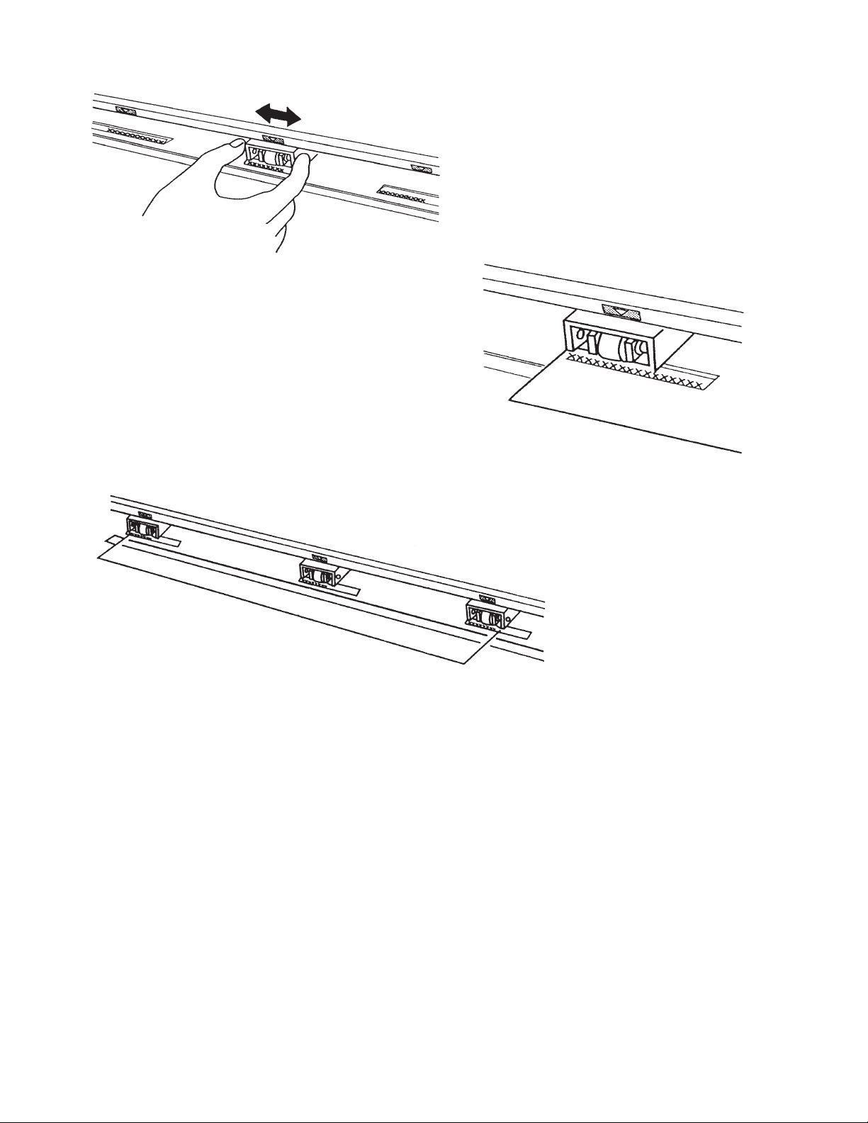
(4) Adjust the pinch roller to position on
the upper part of grit roller. And position
the pinch rollers about 2.5mm each from
the left and right sides of the loaded
material.
(5) Roller alignment seals with tmark
are positioned on the posts of grit
rollers. Line up the edge of the
material paralled to the roll.
Adjusting the pinch rollers on the left
and right edges of the film by t
mark, turn the pinch lever handle
forward to lower the pinch roller in
place.
(6) Turn on the cutter by pressing the
power switch on the left side.
Initialization is then performed when
loading the film is completed.
14
4.3 Setting the Cutting Mode
This function lets the user register four different groups of cutting conditions and pen mode in the
cutter’s memory, which is useful when using the cutter with multiple software applications. The
desired group can be quickly loaded by simply pressing the function key F1 according to the media.
The quality of cutting operations is determined by the settings of the five variables below.
Blade length and type-Adjust the blade length according to the thickness of the material.
Cutting Offset Set these conditions according to the combination
Cutting Speed of material and cutter blade you are using (see the
Cutting Force table below).
Cutting Accel
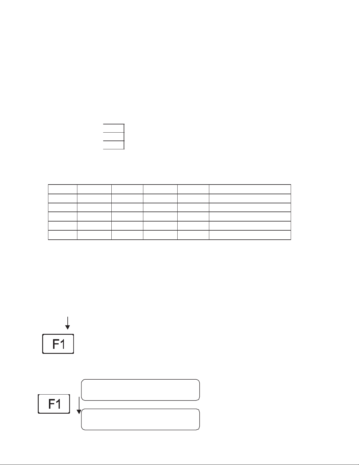
¬Default Value of Cutting Conditions
MODE OFFSET SPEED FORCE ACCEL SHEET
CUT1 0.30mm 30 step 90gm 1.00 Cast Vinyl
CUT 2 0.30mm 80 step 110gm 1.00 Calendared Vinyl, Masks
CUT 3 0.55mm 20 step 120gm 1.00 Ultra-Cut II, Reflective
CUT 4 0.30 mm 40 step 50gm 1.00 Non-Cutting
PEN 30 step 45gm 1.00 Pen, Design Plotting
Note :These selected conditions greatly affect the finished quality of cutting or plotting.
Raising the SPEED and ACCEL values results in lower precision but reduces the
overall cutting time. This is useful when testing runs.
Lowering the SPEED and ACCEL values results in higher precision but
increases the overall cutting time.
Procedure
ROLL 1 : Press the F1 key to select ROLL 1 mode
To change the settings of a group of cutting mode, CUT1, CUT2, CUT3,
CUT4, and PEN MODE, press the function key F1 corresponding to the
Type of material that is to be cut.
The upper row of the display changes as shown to the CUT1..CUT2.. to PEN MODE.
CUT 1 0.30 mm
30 step 90 gm
CUT 2 0.30 mm
80 step 110 gm

15
Press the function key F1 until selection you want is displayed.
Warning : When performing a Cutting Test or data is being transmitted from the computer,
the mode cannot be changed, and the submenu below appears.
4.4 Setting the SPEED, OFFSET and FORCE
Each item described below is displayed for CUT1-CUT4 and can be changed as shown.
SPEED F2
Set the travelling SPEED during testing (cutting speed from the computer is dominant).
OFFSET F3
Set the offset of the cutter blade’s tip from the center of the cutter pen.
The cutter comes with a preset OFFSET adjustment value for each type. To set the blade
OFFSET adjustment, select the type of cutter blade to be used. If the OFFSET valuse is set
to 0, the cutter goes into plotting mode.
FORCE F4
Set the pressure to be applied by the cutter blade or pen tip against the material after testing.
ACCEL
Set the acceleration rate of the pen during cutting or plotting.
The table below describes the specifiable range of each condition.
CONDITION RANGE REMARKS
SPEED(step) 5 to 80 5, 10, 15, …, 80
OFFSET(mm) 0.00 to 1.00 0.00, 0.05, 0.10, …, 1.00
FORCE(gm) 30 to 500 30, 35, …, 160, 170, …, 500
ACCEL 1.00 to 2.00 1.00, 2.00
CUT 3 0.55 mm
20 step 120 gm
CUT 4 0.30 mm
40 step 0.50gm
PEN MODE
30 step 0.45 gm
UNABLE TO CHANGE
WHILE PLOTTING

16
Procedure : To change the value of SPEED, OFFSET, FORCE, press the corresponding Fkey
Press the F2 key to select SPEED.
Press st keys to change and get your desired value.
Press the ENTER Key to set blinking value.
Press the F3 key to select OFFSET.
Press st keys to change and get your desired value.
Press the ENTER key to set blinking value.
Press the F4 key to select FORCE.
Press these keys to change and select the desired value
Press the ENTER key to set the blinking value.
The selected value blinks until the changed value is recorded in the memory.
When all of the displayed settings are correct, press the key to register the group of
conditions in the cutter’s internal-memory.
Note :
Before beginning actual cutting, be sure to check that the cutting conditions are suitably
set as described in Section 4.5, “Running the Cutting Test.” The FORCE and SPEED
values should be gradually raised while running cutting test.
Depending on the type and thickness of the sheet, fine adjustment of the OFFSET may
be required.
CUT 1 0.30 mm
30 step 90 gm
CUT 1 0.30 mm
30 step 90 gm
CUT 1 0.30 mm
30 step 90 gm
17
4.5 The Cutting Test
The function allows the user to check the suitability of the condition settings. If the
test results are not satisfactory, adjust the settings as described in Section 4.3.
Warning : The cutter carriage starts moving as soon as a cutting test is selected. To avoid
injury to yourself and damage to the cutter, load the material before pressing the
TEST mode and then keep your hands, and other obstacles out of the vicinity of the
cutting mat and material.
Procedure
ROLL 1 : Press the key to select ROLL 1 mode.
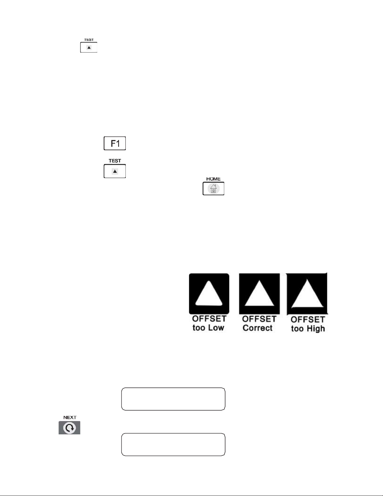
TEST : Press the key.
If the test results are satisfactory, press the key to return to the preceding menu.
If not, proceed to the previous step.
HOME : By pressing the corresponding key, adjust the each value of 0.30mm(OFFSET)
30step(SPEED), 90gm(FORCE), in CUT1 MODE for example.
Referring to the figures of Section 4.3, gradually adjust the corresponding values while checking the
results by running a cutting test.
4.6 Setting the Acceleration
This function allows the user to set the speed at which the material movement starts.
Procedure
Press the NEXT key
CUT 1 0.30 mm
30 step 90 gm
ACCEL : 1.00
SCALE : 1.00

18
Press the F3 key to set the ACCEL Value, display value will blink.
Press these keys and select a value from either 1.0 or 2.0 as desired.
To register the desired value, press the ENTER key
The range of value :1.00, 2.00 refer to the Section 4.3 for the optimum
value of ACCEL
Press HOME key to return to the cutting mode.
4.7 Setting the Scale
This function allows the user to change the size of the design by scaling.
PROCEDURE
Press the NEXT key
Press the F4 key for the desired SCALE value, then LCD will blink.
Press st keys and select your desired value ranging
from 0.50…… 10.0
Press ENTER to set blinking value and register
Press HOME key to return to the cutting mode.
CUT 1 0.30 mm
30 step 90 gm
ACCEL : 1.00
SCALE : 1.00

19
4.8 Setting the Measurement Unit
This function allows the user to set the size of material in mm or inch unit in cutting or pen
plotting
PROCEDURE
Press the NEXT key
Press the NEXT key
Press the F4 key to change the measurement unit, the display unit will blink
Press the these keys and select the desired unit. SIZE will change automatically
when UNIT alters.
To register the desired value, press the ENTER key.
Press the HOME key to return to the cutting Mode.
CUT 1 0.30 mm
30 step 90 gm
ACCEL : 1.00
SCALE : 1.00
SIZE : 32004
UNIT : mm
20
4.9 Axis Alignment
This function lets the user align the cutting axes to match the pre-printed axes on the material in
order to correct any deviation in axes and origin position between the cutter and the material
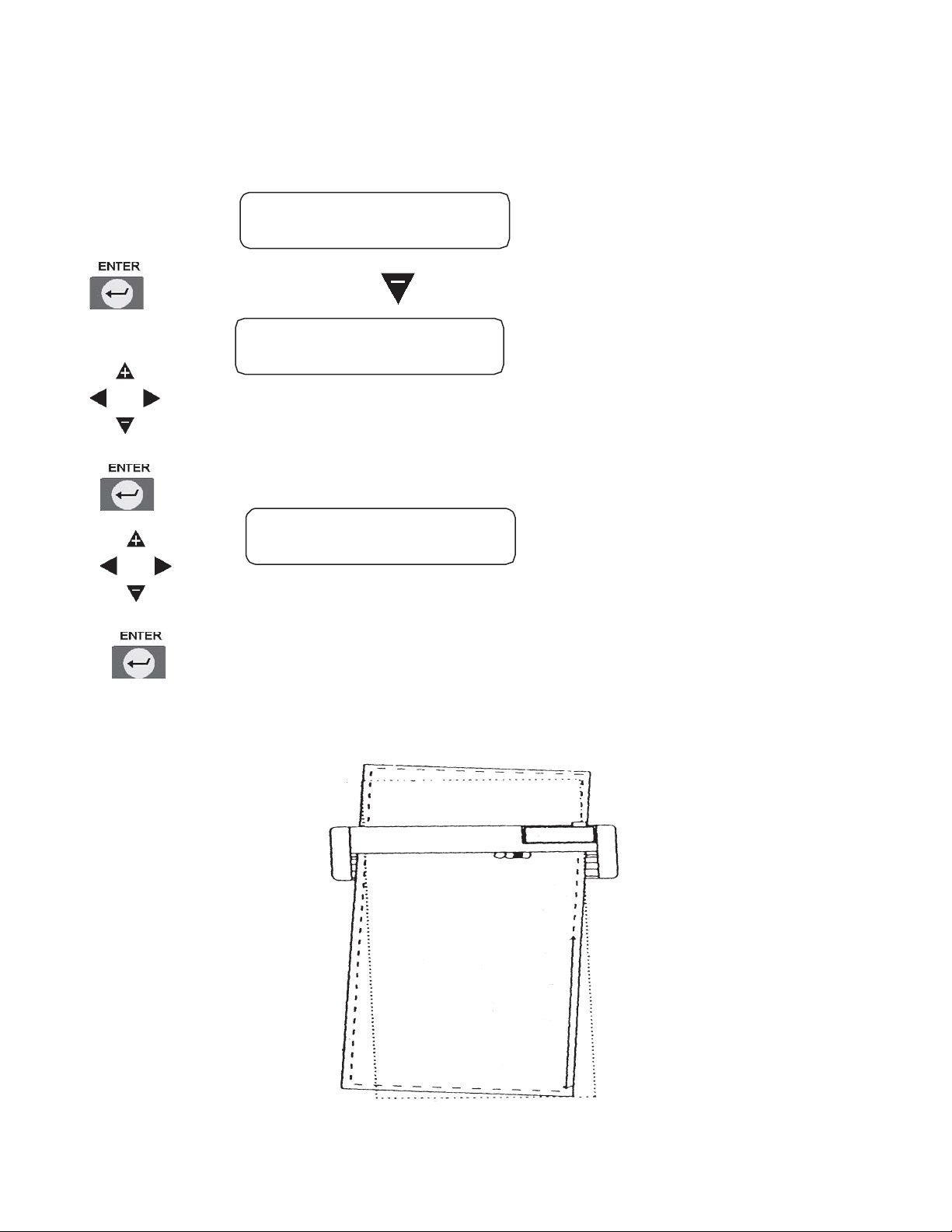
PROCEDURE
Press ENTER key and Key simultaneously
Press position direction key to get ALIGN POSITION 1 value
Press ENTER key to memory ALIGN POSITION 2 value
Press position direction key to get ALIGN POSITION 2 value
Press ENTER key to memory ALIGN POSITION 2 value, then return to cut
mode.
CUT 1 0.30 mm
30 step 90 gm
ALIGN POSITION 1
X= 0 Y= 0
ALIGN POSITION 2
X= 0 Y= 0
This manual suits for next models
1
Table of contents
Other BREN Cutter manuals


Popular Cutter manuals by other brands


Würth
Würth EMS 12-A Translation of the original operating instructions

Intec
Intec ColorCut LC600 Series installation guide

Xhorse
Xhorse Dolphin XP-005L user manual

Clarke
Clarke CHT518 quick start guide

Makita
Makita CE001G instruction manual

Lincoln Electric
Lincoln Electric OPTITOME2 HPC III instruction manual


