BREN Razor 700 Series User manual

V1 NOV 2016
BREN 700-Series Razor
User Manual
BREN Inc.
1-800-826-3991
8256 Horton Highway
College Grove, TN 37046
www.BrenInc.com
All rights reserved. 2016
Quality Marking Products Since 1972

BREN 700-Series UserManual
Important Information
Thank you for purchasing the BREN 700-Series Razor Cutter.
Before you use the cutting plotter, please make sure that you have read the
safety precautions and instructions below.
Caution
!
SAFETY PRECAUTIONS!
For safety concern, please always hold the cutter firmly from the bottom while moving
it. Do not move the cutter by clasping the depression area on both sides.
Do not shake or drop the blade holder, a blade tip can fly out.
During an operation, do not touch any of the moving parts of this machine (such as the
carriage). Also be careful to make sure that clothing and hair do not get caught.
Always connect the power cable to a grounded outlet.
Always use the accessory power cable which is provided. Do not wire the power cable
so that it becomes bent or caught between objects.
Do not connect the power cable to branching outlet to which other machines are also
connected, or use an extension cable. There is danger of overheating and of
mis-operation of the machine.
Keep the tools away from children where they can reach.
Always put the pinch rollers within the white marks.
Important Information
O (Correct)
Hold from the bottom X(Incorrect)
Hold the depression area

BREN 700-Series User Manual
Important Information
Warning
Never press the top release grip and pull the bottom release grip at the same time as
the pictures shown below:
O (CORRECT) X(INCORRECT)
Press down
DISABLE
Press down
Stop bar
ENABLE
Pull up bottom to release grip
Note:
In case the grips clipped
together due to your
wrong operation, please
use a pair of tweezers to
pull out the stop bar
when pressing down the
top release grip. Keep
the stop bar outside then
release the grips as the
right figure.
BREN 700-SeriesUser Manual
General Information 1-1
Chapter 1 General Information
1.1 Introduction
BREN 700-Series Razor cutting plotters have been designed to produce computer-
generated images or perform contour cutting on sheets or rolls ofvinyl media.
This manual covers the following models ofBREN 700-Series Razor series cutting plotters:
‧BREN 724 for media width: 2 inches - 24 inches.
‧BREN 740 for media width: 2 inches - 40 inches.
‧BREN 752for media width: 2 inches - 52 inches.
1.2 Package Items
Standard Item Q
Qu
ua
an
nt
ti
it
ty
y
1. Cutting Plotter 1
2. Stand Set ( for BREN 724 Razor only )
2 piece of T-shape stand
1 piece of stand beam
20 pieces of M6 screws
1 piece of M5 L-shape hexagon screw driver
1 piece of Installation Guide for Stand Set
1
Above values are cut widths.
The package of the 724 Razor model contents the items listed below, please check
carefully. If you find any item missing, please consult your local dealer for further
assistance.

BREN 700-Series User Manual
General Information 1-2
3. Media Support System Package
Items
740-752 724
1 set of Roll Media Flange (2 pieces)
V
V
1 set of Roll Holder (2 pieces)
V
V
1 set of Roll Holder Guide Bushes (4 pieces)
V
V
1 set of Roll Holder Support (2 pieces)
V
V
1 piece of M6 L-shape hexagon screw driver
V
V
1 piece of Installation Guide for Roll Holder
V
V
1 set of Desktop Support Brackets (2 pieces)
V
4 pieces of Plastic Foot
V
4 pieces of M4 screws
V
12 pieces of M6 screws
V
1
4. Accessories
1 piece ofUser’s Compact Disk
1 piece of AC power Cord
1 piece of data cable (USB cable:3m)
1 set ofBlade Holder Assembly (Installed in tool carriage of the
cutting plotter)
1 piece of Blade (Installed in Blade Holder)
1 piece of Safe Blade
1 piece of Tweezers
1 piece of Ethernet Cable
1
1.3 Product Features
The following are the main features ofthe BREN 700-Series Razor cutting plotters:
‧Triple-port connectivity provides you with greater flexibility
‧Up to 600 gram cutting force
‧Up to 1530 mm per second (60 ips) cutting speed (at 45° direction)
‧Guaranty 10-meter tracking
‧User friendly and multi-language control panel
‧Ingenious media basket (optional item)
‧Enhanced Automatic-Aligning System for automatic contour cutting
1 piece of M4 L-shape hexagon screw driver
BREN 700-Series User Manual
General Information 1-3
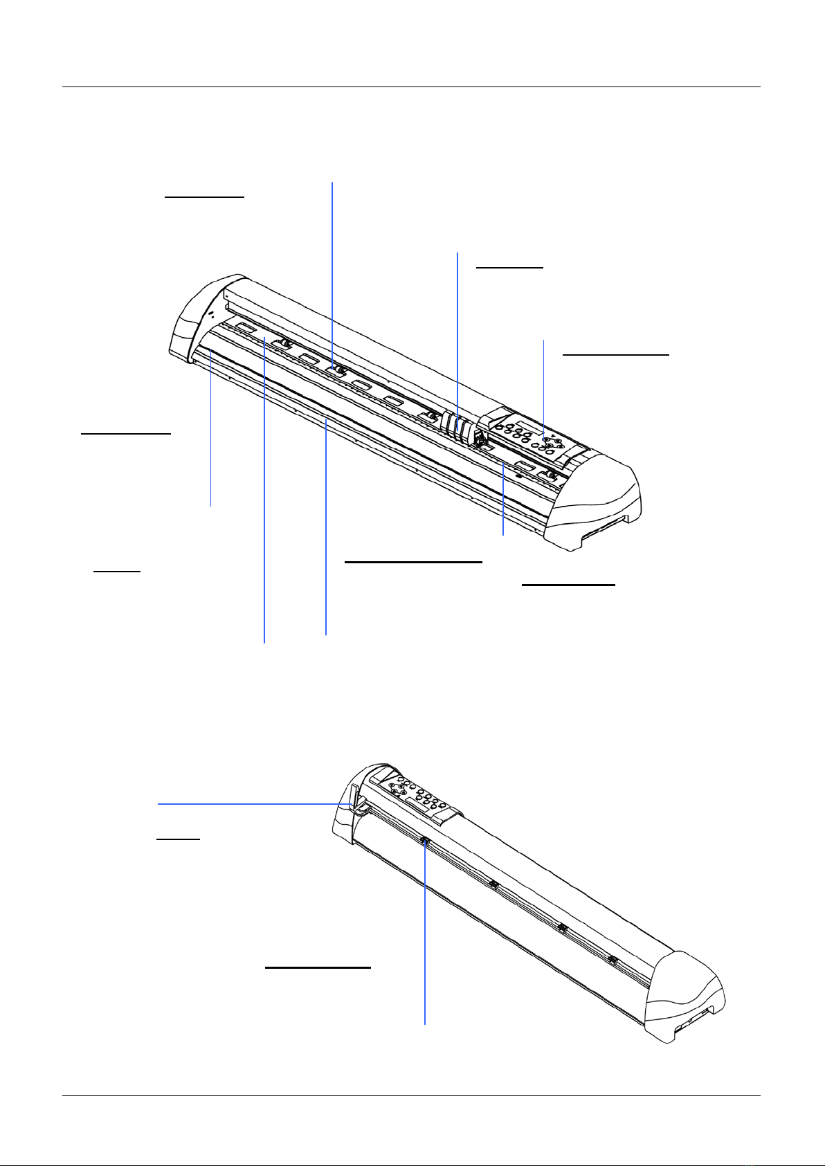
1.4 Appearance ofBREN 700-Series Razor.
1.4.1 The Front View (Figure 1-1)
1.4.2 The Back View (Figure 1-2)
Pinch Rollers –
hold the media during
cutting.
Lever –
raises or lowers the
pinch rollers.
Figure 1-2
Control panel – consists of 14
control keys and 1 LED and 1 LCM
showing messages and menus.
Cutting Strip –provides the
protection of blade when the blade is
cutting.
Carriage – performs the
cutting with the installed blade
and pen with AAS module.
Alignment Rulers –
media can be aligned
with the clear guide line
marks.
Grit Areas – move
the media back and
forth during operation.
Cut Groove –
slice off the extra
media easily along
this groove.
Cover – provides the
surface for holding and
supporting media while
performing cutting.
Figure 1-1

BREN 700-Series User Manual
General Information 1-4
1.4.3 The WholeView of BREN 700-Series Razor (Figure 1-3)
Figure 1-3
Roll Holder – holds
and supplies the roll
media for cutting.
Roll Holder Guide
Bushes –serve to
keep the roll media in
place when media is
pulled from the roll.
T-Stand –supports
the cutting plotter
Stand Beam –
stabilizes the body.
Roll Holder
Support – supports
roll holders.
T-Stand –supports
the cutting plotter
BREN 700-Series User Manual
General Information 1-5
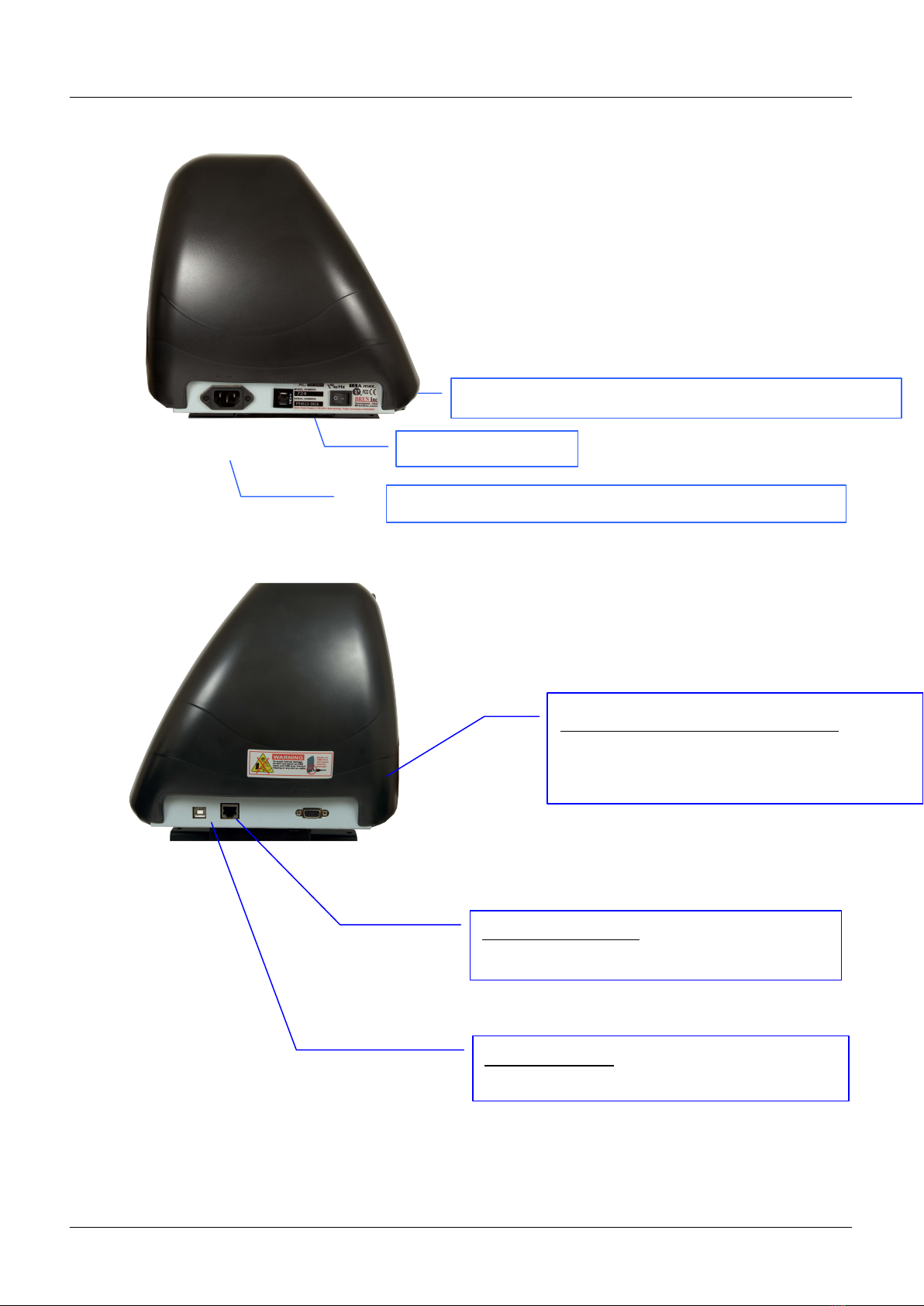
1.4.4 The Left-hand Side (Figure 1-4)
1.4.5 The Right-hand Side (Figure 1-5)
Fuse – 3 Amp.
AC Power Connector – used to insert the AC power cord.
Power Switch – On when switches to [I]; Off to [O]
Figure 1-4
Serial Interface Connector (RS232C) – used
to connect the cutting plotter to a computer
through a serial interface cable.
Figure 1-5
USB Connector – used to connect the cutting
plotter to a computer through a USB cable.
Ethernet Connector– used to connect your
computer to a local area network.

BREN 700-Series User Manual
Installation
2-1
Chapter 2 Installation
2.1 Precaution
Please read below information carefully before you start installation.
Notice 1
Make sure the power switch is off before installing the cutting plotter.
Carefully handle the cutter to prevent any injuries.
Notice 2 Choosing a proper place before setting up the cutting plotter
Before installing your cutting plotter, select a suitable location, which meets the following
conditions.
The machine can be approached easily from any direction.
Keep enough space for the machine, accessories and supplies.
Keep the working area stable, avoiding sever vibration.
Keep the temperature between 15 and 30
℃
(60-86oF) in the workshop.
The relative humidity of the working environment should be between 25% to 75%.
Protecting the machine from dust and strong air current.
Preventing the machine from direct sunlight or extremely bright lighting.
Notice 3 Connecting the Power Supply
Check the plug of the power cord to see if it matches with the wall outlet. If not, please contact
your dealer.
Insert the plug (male) into a grounded power outlet.
Insert the other end (female) of power cord into theAC connector of cutting plotter.
BREN 700-Series User Manual
Installation
2-2
2.2 Media Support System [for BREN 700-Series Razor]
Step 1
Please examine supplied items in the accessory box of stand carton:
1 set of roll media flange (2 pieces)
1 set of roll holder (2 pieces)
2 pieces of base beams
2 pieces of side beams
1 piece of stand beam
2 pieces of roll holder support
20 pieces of M6 screws
1 piece of M5 L-shape hexagon screw driver
1 piece of installation guide for stand set
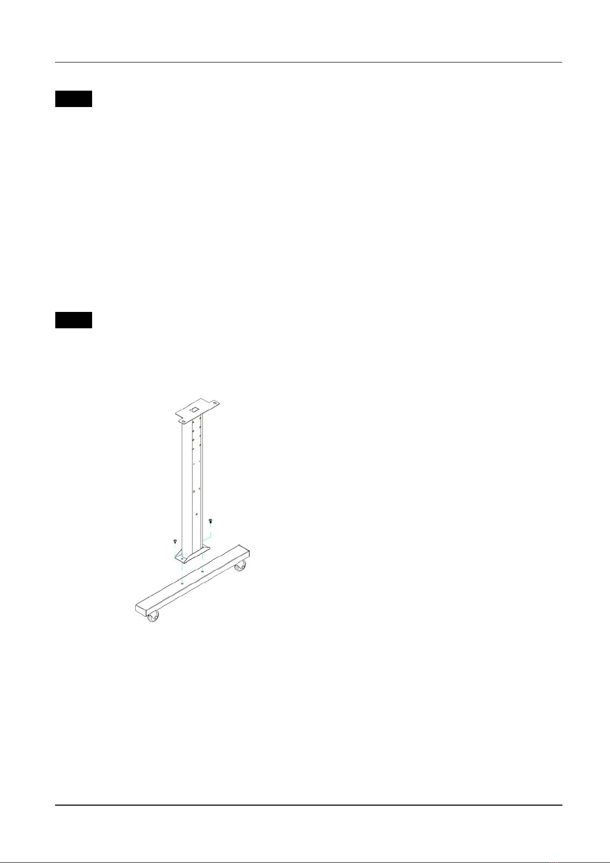
Step 2
Remove the plotter body and the accessories from the shipped carton.
Assemble the base beam to the side beam with 2 screws to form a T-shape stand.
(See Figure 2.2-1)
Figure 2.2-1
BREN 700-Series User Manual
Installation
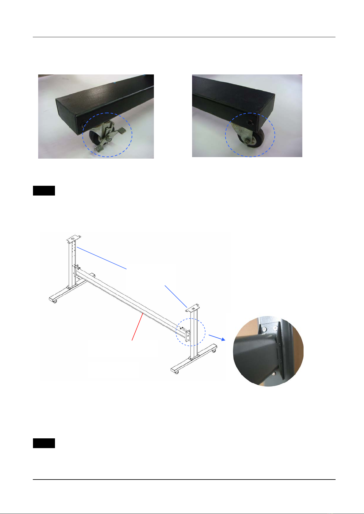
2-3
Please pay attention to the direction of the base beam (the wheel on the front end of the
beam comes with a break while the rear one is on its own).
Step 3
Place the stand beam upright on the T-stand and follow number to assemble (See
Figure 2.2-4 & 2.2-5). There is hexagon socket head screws fasten on the T-stand on both
side taken as locating pins.
Step 4
Position the stand beam perpendicularly to part and put the screws into the holes and
tighten them as Figure 2.2-5. Then the complete picture of stand will be like Figure 2.2-4.
Front Rear
Figure2.2- 2
T-Stand
Stand beam
Figure 2.2-4
Figure 2.2-5
Figure2.2- 3

BREN 700-Series User Manual
Installation
2-4
Step 5
Remove the cutting plotter from the carton. Position your stand under the plotter, on the
bottom of the plotter, there is one hole on each side in the position corresponding to the
locating pins, so the locating pins can be located into the holes. Then insert the screws into
the holes on the stand to fix the plotter and tighten them up as shown in Figure 2.2-6.
Screws
Figure 2.2-6

BREN 700-Series User Manual
Installation
2-5
Step 6
Insert the roll holder support with the screws into the holes of the stand, and then tighten them
up as shown in Figure 2.2-7. You could decide roll holder support’s position by inserting into
different holes.
Step 7
Place the roll holder 1 onto the roll holder support (Figure 2.2-8).
3 screws
Figure 2.2-7
Roll holder support
Roll holder 1
Figure 2.2-8
Roll holder support
Roll holder 2
BREN 700-Series User Manual
Installation
2-6
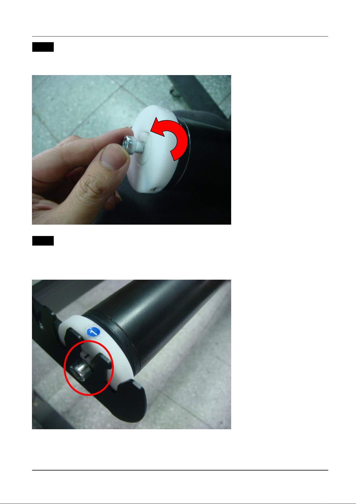
Step 8
Turn the screw counter-clockwisely for around three times after unpacking roll holder 2
(Figure 2.2-9).
Step 9
Insert the end of the roll holder without the damper into the left roll holder support and then
insert the end of the roll holder with the damper into the right roll holder support. Ensure the
white protrusion is wedged in the groove (Figure 2.2-10).
Figure 2.2-10
Figure 2.2-9
BREN 700-Series User Manual
Installation
2-7
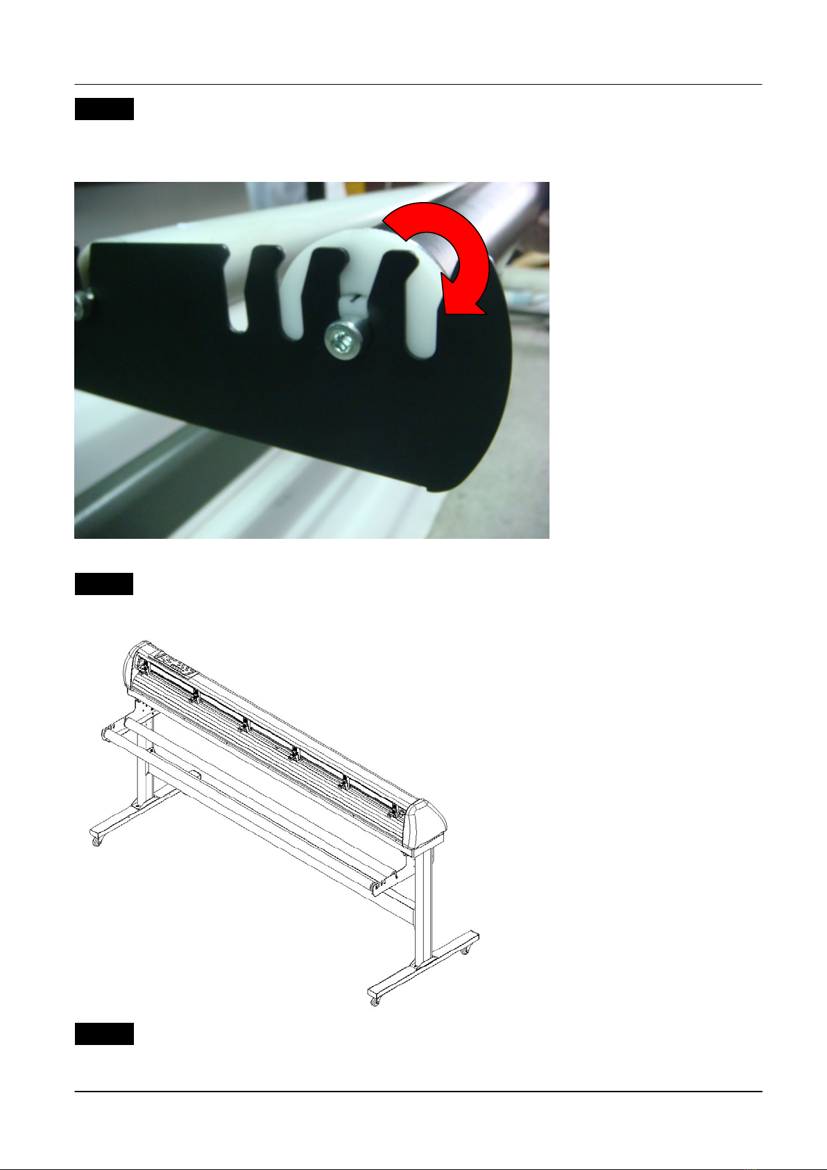
Step 10
Tighten the screw on the damper until it is securely attached to the right roll holder support
(Figure 2.2-11).
Step 11
Lastly, the complete picture will be shown like below. (Figure 2.2-12)
Step 12
Please refer to user manual section 4.1 to learn how to load the roll media.
Figure 2.2-12
Figure 2.2-11

BREN 700-Series User Manual
Installation
2-8
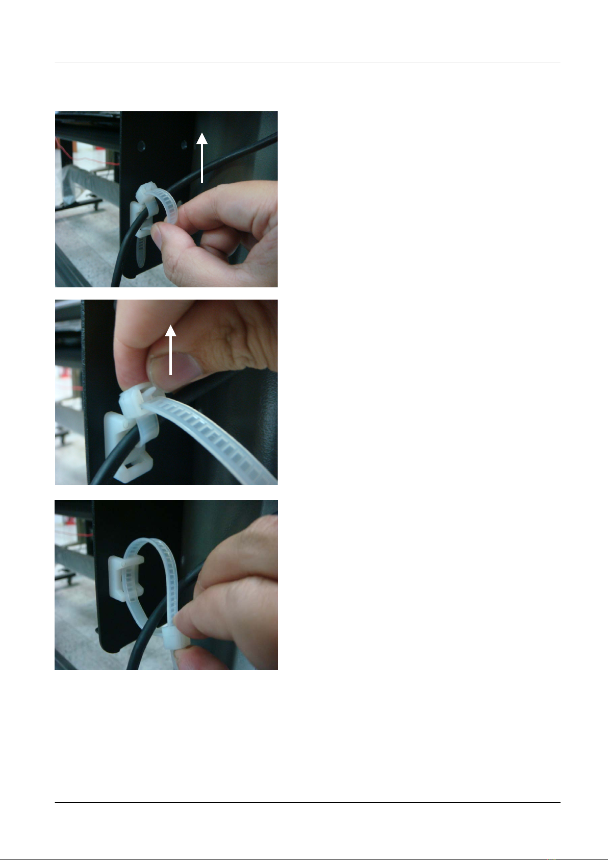
2.3 USB Cable Tie and Saddle
The USB cable tie and saddle assembly for the stands with Flexible Media Support System only.
Step 1 Insert the cable tie into the upper hole of cable saddle from bottom to top.
This side up
Step 2 Place the USB cable into the cable tie and tighten the cable tie.
Step 3 Insert the cable tie end into the lower hole of cable saddle to finish the job.
BREN 700-Series User Manual
Installation
2-9
Untied way: pull out the cable tiepull up the pinrelease the cable tie.
Pull out the cable tie
Pull up the pin
Release the cable tie

BREN 700-Series User Manual
Installation
2-10
Desktop Support Brackets
2.4 Desktop Flexible Media Support System [For BREN 724 Razor]
Step 1
Please examine the following items in stand carton’s accessory box:
1 set of Roll Media Flange (2 pieces)
1 set of Roll Holder (2 pieces)
1 set of Roll Holder Guide Bushes (4 pieces)
1 set of Roll Holder Support (2 pieces)
1 set of Desktop Support Bracket (2 pieces)
4 pieces of Plastic Foot
4 pieces of M4 screws
12 pieces of M6 screws
1 piece of M4 L-shape hexagon screw driver
1 piece of M5 L-shape hexagon screw driver
1 piece of M6 L-shape hexagon screw driver (for adjusting the screws of Roll Holders)
1 piece of Installation Guide for Roll Holder
Step 2
Put the 4 Plastic Foot under the Roll Holder Support and insert the M4 screw into the hole of
Plastic Foot and tighten them with the M4 L-shape screw driver. (Figure 2.3-1
)
Step 3 Position the Desktop Support Brackets beside the Roll Holder Support and insert M6
screws into the Roll Holder Support and tighten them with M6 L-shape screw driver. (Refer to
Figure 2.3-2).
Figure 2.3-1
M4 screws
Plastic
M4 screws
Roll Holder Support
Figure 2.3-2
M6 screws Roll Holder Support
M6 screws

BREN 700-Series User Manual
Installation
2-11
Step 4
Put the bottom of machine in lateral, and position the Roll HolderAssembly beside the bottom
of the machine. Then, insert the M6 screws into the holes of Roll Holder support assembly
and tighten them with M6 L-shape screwdriver. Like Figure 2.3-3.
Step 5
Place the two roll holders into the holes of Roll Holder Support (Figure 2.3-4). To install the roll
holder with damper, please refer to chapter 2.2, step 8 to step 10.
Step 6
The complete Desktop Media Support System will be shown as in Figure 2.3-5.
Figure 2.3-5
Figure 2.3-3
M6 screws
Screw holes
Roll Holder Assembly
Figure 2.3-4
Roll Holders
BREN 700-Series User Manual
Installation
2-12
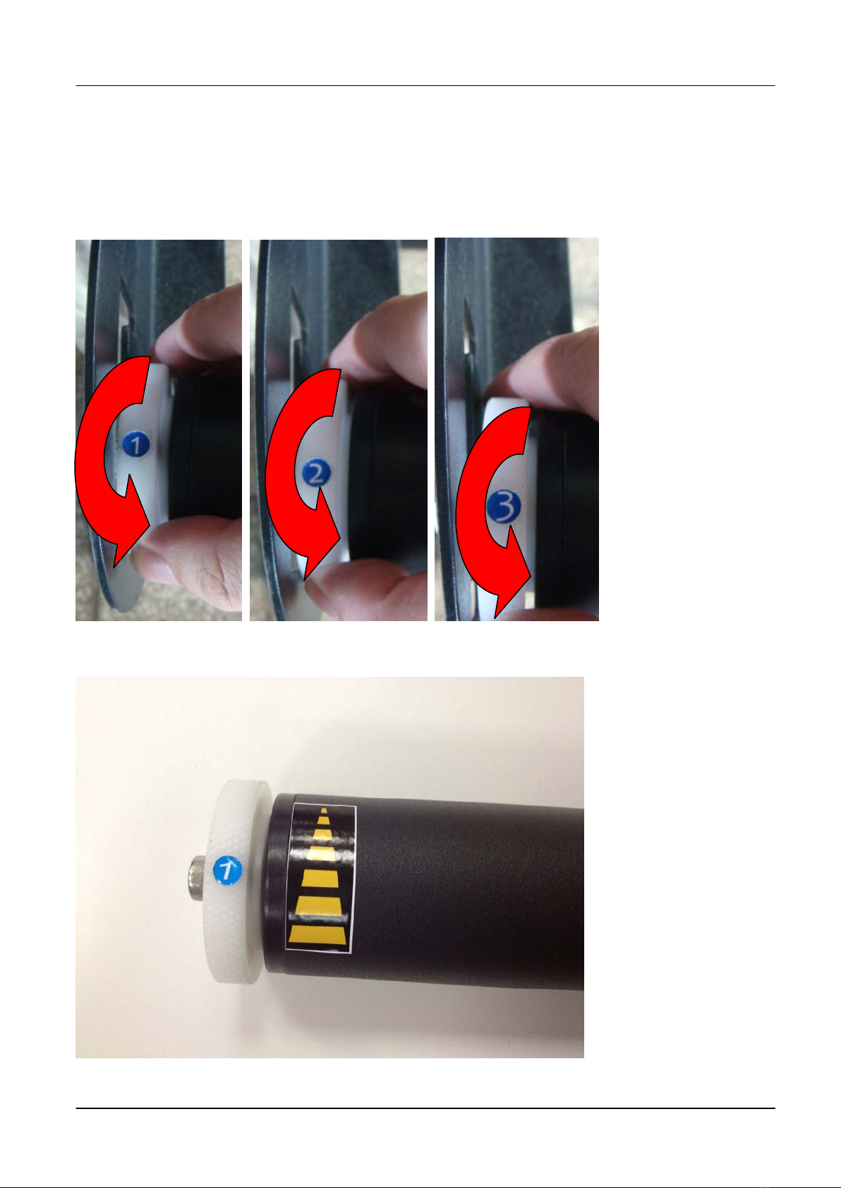
2.5 Instruction of Damper Roller
Turn the wheel as instructed below to adjust damping. The bigger the number is, the stronger
the damping. The volume symbol sticker indicates the damping level (Figure 2.3-6, 2.3-7).
Figure 2.3-6
Figure 2.3-7
This manual suits for next models
3
Table of contents
Other BREN Cutter manuals


 Operator's manual")


