manuals.online logo
Brands
  1. Home
  2. •
  3. Brands
  4. •
  5. BrewBuilt
  6. •
  7. Brewing System
  8. •
  9. BrewBuilt BrewSculpture LOW RIDER User manual

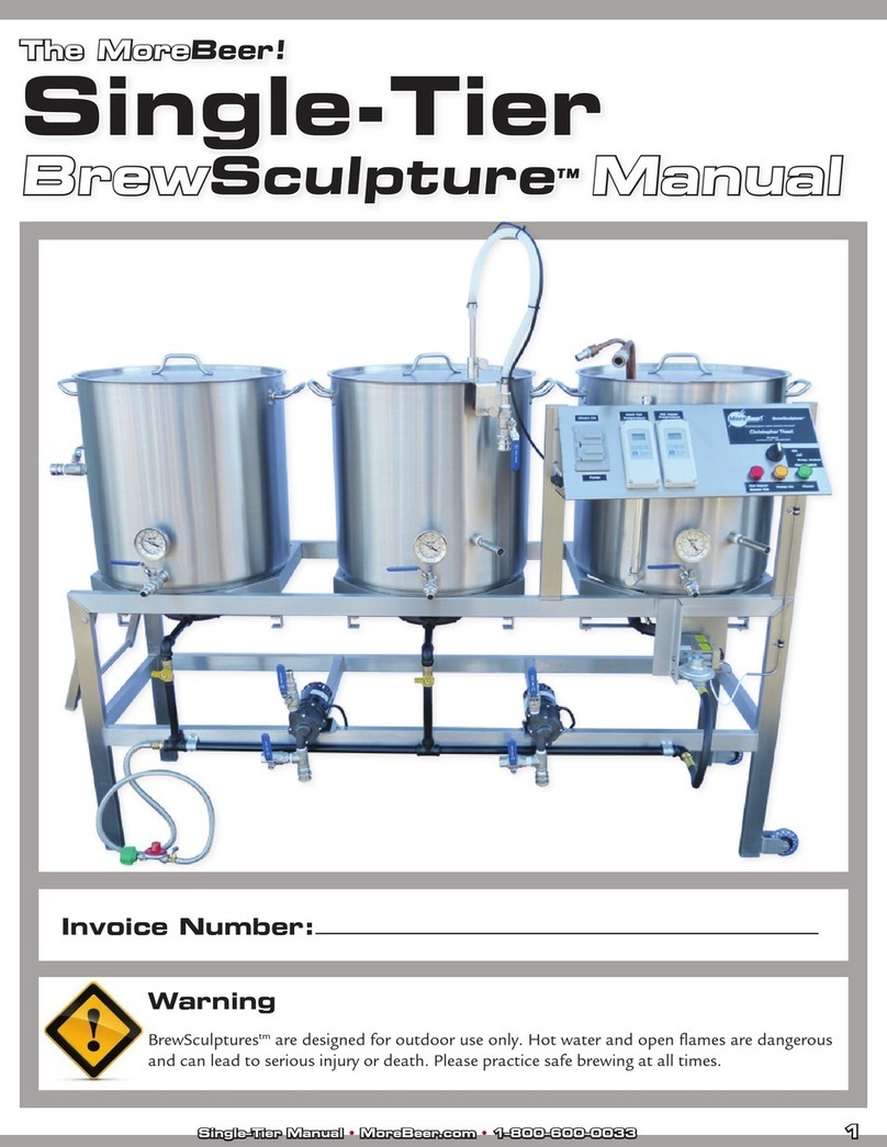
BrewBuilt BrewSculpture LOW RIDER User manual

So you’ve just received your Single-Tier BrewSculpture™, and like
a kid during their birthday, you’ve torn through the wrapping
and have all of your new toys lying in front of you. Once you’ve
goen through it all, take stock of the items listed below:
What’s Included
1xStainless Steel Single-Tier Stand
3xStainless Steel BrewBuilt™ Keles
1 x False Boom Screen For Mash Tun
1 x Stainless Steel Sparge Arm Assembly
1xCopper Heat Exchanger
2 x March Pump Assemblies
1 x Whirlpool Assembly for Boil Kele
6xTubing Setups
1 x Wheelbarrow Arm (Under Boil Kele)
2xWheels
2xSlingBlade™ Electric Elements (4 x 1 BBL System Only)
1 x Control Panel
1 x Boom Box for Power Distribuon (L6-30 Connecons)
2 x Hot Liquor Tank/Boil Kele Float Switch/Temp Probe Assemblies
1 x Sparge Arm Float Switch/Temp Probe Assembly
Table OF Contents
PAGE 1........................................................Intro & What’s Included
PAGE 2..........................................Assembly Requirements & Tools
PAGE 2 – 3........................................Seng Up Your BrewSculpture
PAGE 3 –10........................................................................Brew Day
PAGE 11..........................................................Cleaning & Sanizing
PAGE 11–12...............................................................................FAQ
PAGE12..........................................................................Tips&Tricks
SAFETY WARNING
Electric BrewSculptures™ are designed to be used with a GFCI.
Hot water and high current are dangerous and can lead to serious
injury or death. Please pracce safe brewing at all mes.
Digital Electric BrewSculpture™ Manual
LOW RIDER
1
With all of the included items and tools in front of you, you’re ready to
setup your BrewSculpture. Let’s start at the right of the BrewSculpture,
and work our way to the le…
The far right kele locaon is going to be where we posion the hot liquor
tank. The hot liquor tank is the vessel that will heat and store your sparge
water, which is used to rinse all of the sugars from the grains in the mash
tun and into the boil kele aer you’ve nished mashing. This kele will
be placed on the right side, and will need ve items installed on it. These
are: A ball valve and quick disconnect on the boom coupler, a stainless
steel maximizer on the inside of that boom coupler, a SlingBlade™
Electric Element, Float Switch/Temperature Probe Assembly and last, but
not least, your 3" Face x 2" Probe thermometer. Install the SlingBlade™
into the TC port. You’ll also need to install the heat exchanger in the hot
liquor tank prior to re-circulang your mash and sparging.
The middle kele locaon is where you’ll posion your mash tun. Your
mash tun is where all of the grains will be during the mashing and sparg-
ing process, and will receive four things during setup: A ball valve and
quick disconnect combinaon, a 3" Face x 6" Probe thermometer (the
probe will protrude into the grain bed), the perforated false boom
screen, and a stainless steel maximizer. First, install the ball valve aer
wrapping plumber’s tape on the boom coupler. With this in place, in-
stall the supplied silicone seal around the outside of the mash screen.
Then, take the perforated false boom screen, and insert it into the ket-
tle with the single-handle side facing upward. It is important that this
rests at on the boom, with minimal gapping between the screen and
the sides of the kele. Next, screw the quick disconnect into the inside
of the boom coupler and aach the stainless maximizer with the bend
in the tube aimed down toward the boom of the kele. Once this is in
place, we’re ready to screw the thermometer into the top coupler using
3–4 wraps of plumber’s tape. We’ll aach the stainless steel sparge arm
assembly to the side of the mash tun aer we’ve doughed-in.
IMPORTANT NOTE: Your Digital BrewSculpture™does not include
an extension cord for the control panel because we do not know how far
your BrewSculpture™ will be from an outlet. Please purchase a standard
three-prong extension cord of the appropriate length to power your
digital BrewSculpture™separately.
Most items should have come assembled; however some of them may
require adjusng or assembling. If any of these items appear to be miss-
ing, please nofy our customer service team.
TOOLS NEEDED FOR ASSEMBLING & MAINTENANCE
• Flat Head Screwdriver (Hose Clamps)
• Phillips Head Screwdriver (Pump Head)
• Crescent Wrench (Quick Disconnects, Ball Valves)
• Plumber’s / Teon Tape (Any Male Pipe Threads)
• Line Brush (Tubing Assemblies)
• White Scrub Pads (Cleaning Keles and Frame)
• Extension Cord (Needed For Control Panel)
• 15 AMP 115V GFCI protected outlet for the pumps & control panel.
• 30 AMP 220V GFCI protected outlets.
• 30 AMP 220V Extension Cord may be needed if your power is more
than 5’ from the boom box.
AEMBLY REQUIREMENTS SEING UP
2
WORT CHILLER: Used at the end of your boil to quickly cool your wort to yeast
pitching temperatures. (The included Convoluted Heat Exchanger can be used as an
immersion chiller.)
INGREDIENTS: Sounds like a no-brainer, but it’s best to ensure all grains / hops
are there prior to starng!
FERMENTERS: It’s best to have your fermenter or fermenters cleaned and ready
to sanize before you brew, but if not, have them around so they can be cleaned during
the brew.
OTHER TOOLS: Spoon, mash paddle, refractometer, note pad, etc.
So you’ve goen your whole BrewSculpture™setup, and can’t wait to
start brewing! We’ll go through the process of doing so, and will try to
help keep your brew day as quick, easy, and ecient as possible. We
would like to start by recommending that once all of your keles have
been setup, you may want to do a water run starng with 4–5 gallons in
your mash tun and hot liquor tanks. Re-circulate the water in the mash
tun, then move the tubing around to mimic a sparge into your boil ket-
tle. This is not only done to remove any dust or stainless shavings from
manufacturing, but is also recommended so that you understand how
everything connects and ows prior to brewing with wort. Another thing
to look for while performing the water run is any leaky threads or tubing
– beer to leak water than wort!
At this point, all of your keles should be setup, and now you probably
have a couple pieces of equipment sing around. These would be your
pieces of tubing with quick disconnects, the copper heat exchanger, and
your stainless steel sparge arm. The stainless sparge arm will install on
the mash tun’s kele wall, and the height is adjustable. Make sure to
plug it into the control panel.
It’s important to have the following items ready at the start of your brew
day:
The le kele locaon is going to be where your boil kele goes. With
this kele in front of you, we’ll want to install four things: Two ball valves
and quick disconnects, the 3" Face x 2" Probe thermometer, and the
stainless steel whirlpool/maximizer. One ball valve will thread on to the
boom coupler, the thermometer will thread into the top coupler, and
the whirlpool/maximizer aach to the quick disconnect threaded into
the inside of the boom coupler’s threads, inside the kele (no plumb-
ers tape required - if it leaks it will just be leaking inside the kele). The
second ball valve will install on your whirlpool coupler.
Your pump assemblies should come with mounng brackets already
mounted to the frame. To install your pumps, simply slide the pumps’
mounng plate into the BrewSculpture™ mounted bracket. Your pump
should be installed so the “inlet” faces down towards the ground and the
pump “outlet” faces up. NOTE: The pump outlet will be labeled on your
pump head with the word “out”. The pumps will need to be plugged into
the power box on the control panel, rather than into the wall. Make sure
the “Pump” indicator on the control panel is NOT on prior to plugging in,
to avoid running the pump dry!
The wheels and control panel should come pre-mounted. If these are
not included or installed, please call our customer service department.
You will need to connect the cables from the keles to the control panel.
These are color coded for easy aachment.
Hang the boom box at a convenient place on the top rail of the stand.
Place close to your power outlet if possible. Connect the 8 pin connector
from the boom box to the control panel. Plug the two female L6-30P
plugs into your elements. The plug on the right goes to the HLT and the
plug on the le goes to the Boil Kele. Plug the male plug into your GFCI.
BREW DAY
3

BREWSCULPTURE ANATOMY
BOTTOM
BOX
TEMPERATURE
PROBE/FLOAT
SPARGE
ARM
WHIRLPOOL
PORT
FOLDING
HANDLE
MASH
TUN
BOIL KETTLE
STAND
TEMPERATURE
PROBE/FLOAT
PUMP 2 PUMP 1
HOT LIQUOR
TANK
HEAT
EXCHANGER
4
With all of your keles setup, all other items in front of you, and a crav-
ing to brew like you’ve never had before, let’s get started! There are
dierent grist raos that work well for dierent brewers and brewer-
ies. If you’re using long tubing lines, you may want to start with more
water (since there will be some liquid that is not in contact with the
grains while it recirculates through your tubing). With our Single-Tier
BrewSculpture™, we recommend starng with a 1.3–1.4 qts water to lbs
of grist rao, and moving up or down from there. An example of how to
nd out the amount of water you’ll need (or how to get your grist rao)
is below. Let’s say your recipe for 10 gallons will include 20 lbs of grain.
In order to nd out how much water (in gallons) you’ll need in the mash
tun, we’ll use this equaon:
1.3 (qts) x 20 (lbs) = 26 qts / 4 (4 qts in a gallon) = 6.5 (gallons)
We’ll want 6.5 gallons in contact with our 20 lbs of grain to achieve a
1.3:1 grist rao. If we were to ll our kele with 6.5 gallons though, we
wouldn’t have it all in contact with the grains. There will be what we call
“foundaon water” under the false boom: Water that is not in contact
with grain. We’ll need to account for that in our equaon, and add that
volume of foundaon water to our 6.5 gallons. In our 15 gallon keles,
we’ll have approximately 2 gallons underneath the false boom. There-
fore, we’ll want to measure out 8.5 gallons to achieve a 1.3 grist rao. In
our 22 gallon keles, we’ll have approximately 2.25 gallons underneath
the false boom, and in the 50 gallon keles we have about 2.5 gallons
of foundaon water. We will transfer this much preheated water from
the HLT using pump #1.
Once we have our strike water in our mash tun, we can turn on the con-
trol panel and set the HLT temperature. We’ll want to heat it up to a
temperature above what you’re actually hoping to mash at, as that tem-
perature will drop once the room temperature grain is introduced and
srred in. This temperature drop will be dependent on how much grain
will be used, how much water you have in the mash tun, and what the
ambient temperature is where you’re brewing. Due to this, it’s hard to
recommend how far above your mash temperature you’ll want to heat
your water to prior to doughing-in. A wide, general range would be be-
tween 6–12 degrees above what you’re hoping to mash at. Example: If
you’d like to mash at 150°F, dough-in at 156°F–162°F.
FLOW OF TUBING
FOR STRIKE
5
Your sculpture has the opon of preheang your water for you. Once you
are comfortable with your installaon you can program it to start when
you are not there. We strongly advise that you not leave the system
unaended on the rst brew to ensure everything is installed correctly.
TO ACCESS THE DELAYED START SCREEN
• Fill your HLT with water and adjust the chemistry
• Make sure your system is set to Enabled
• Select HLT Setpoint, Mash temp +10°F is a good starng place
• Help>Delayed Start
• Press the delayed start buon
• Set your delayed me in 1/10th of an hour increments. For this test
.2hr (12 min) is a good start
• Press Start. The Delayed Start indicator will start blinking indicang
that the mer is running
Aer the mer stops it will turn on the electric element and start heang
the water. It will take about 3.5 hr for the water to heat. If the element
does not turn on, make sure the oat is installed and indicates UP, the
HLT is set to Auto, and the System is set to Enabled.
DELAYED START
SCREEN
6
Before we mash in we will set up the mash schedule into the Mash
Screen.
• Press Mash Mode
• Enter the me for the rst step
• Press Enter
• Enter the temperature for the rst step
• Press Enter
• Repeat for each step
*NOTE: The system works best when the HLT is not warmer than 30°F
above the mash set-point
Start pouring the grain into the mash tun, distribung it as evenly as
possible and srring constantly with a mash paddle. This is done to help
prevent dough balls and clots that will reduce eciency, and possibly
contribute to a stuck sparge. With all of the grain inside the mash tun,
double check the temperature to make sure it’s where you want it, and
aach the stainless steel sparge assembly. At this point in me we can
connect the appropriate tubing for recirculaon. Set up the system for
recirculaon and open the valves.
From the mash tun’s ball valve, we’ll run the longest length of tubing
down to the March Pump inlet. Run one of the other tubing lengths with
(2) quick disconnect ngs from the pump outlet to the heat exchanger
inlet (le female QD), and the other one of those tubing lengths from
the outlet (right male QD) of the heat exchanger to the inlet of your
sparge arm assembly. You’re now ready to re-circulate your mash!
Meanwhile, the hot liquor tank will probably be geng close to our
target temperature soon, so keep an eye on that and turn the element
o once we’ve reached that temperature.
When you are nished press Start on the Mash Screen. This will use the
heat exchanger and the pump to control the mash steps. The mer will
not start ll the current mash step temperature is achieved.
FLOW OF TUBING FOR
RE-CIRCULATING MASH
7
The conversion from mashing to sparging is
rather simple. Close the mash tun’s ball valve,
as well as the ball valve on the March Pump
and sparge arm. Move the tubing running from
the mash tun’s ball valve to the hot liquor tank
ball valve. Take one of the tubing lengths with
(2) quick disconnects and connect the Mash
Tun ball valve to the inlet of the le side pump.
Take another tubing length with (2) quick dis-
connects and connect the outlet of the le
pump to the boil kele ball valve. With the hot
liquor temperature at 170°F (or slightly higher),
open the hot liquor tank and March Pump ball
valves all the way. Now crack the sparge arm
assembly’s ball valve and turn on the pump.
The liquid level should now be dropping in the
hot liquor tank, while rising in the mash tun.
Once 2–3" has gathered on top of the grain
bed, open the boil kele ball valve, and crack
the mash tun ball valve – now we’re sparging!
Press Sparge on the Mash Screen to switch to
the Sparge screen and start the mer.
Make sure that during the sparge you do not
over ll the mash tun, while also not
running the grain bed dry. This will
take a lile ne tuning of the mash
tun ball valve. The sparge process
should take between 45–75 minutes, so if it
seems like your hot liquor tank will be dry aer
20 minutes, it’s best to close the mash tun ball
valve a lile more to slow down the ow. Find-
ing that perfect ow rate may take a few batch-
es, so make note on how far open you have the
valve, and how long it took to sparge at that
posion.
FLOW OF TUBING
FOR SPARGING
8
If you set the power slider on the Sparge Screen to 50% it will keep your
HLT warm while preheang the boil. It will not turn on the boil element
ll the oat switch reads UP and it will kill the HLT element when the HLT
oat reads DN.
Make sure to close the ball valves of your hot liquor tank, mash tun, and
boil kele once the desired volume has been collected in your boil kele.
RUNNING BOIL
At the very beginning of the boil, you’ll most likely experience the “hot
break”. This is idenable by a layer of foam forming on the top of your
wort, and is a good thing unless it spills all over your BrewSculpture™and
kele! To prevent the hot break from a “boil-over”, either reduce the
heat or spray the foam with water out of a spray bole. Blowing on the
foam can help a lile also, but only if the heat has been reduced rst. You
could try using foam control, or “FermCapS” (our part number AD290).
Just add a couple of drops when this foam starts to form, and this should
help reduce it. Aer geng through the hot break, start your mer for
the length of the boil you’ll be doing. 60, 75, and 90 minutes are gener-
ally the most common boil mes, but depending on your brewing style
and recipe, other mes may be appropriate also. Through the boil, you’ll
be adding your hops, adjuncts, and other ingredients as the recipe calls
for them. NOTE: Whole leaf hops will need to be put into a mesh bag,
as they will clog the ball valve if they’re not contained. While your wort
is boiling, you can save me by connecng the long piece of tubing to
the mash tun ball valve, and open it allowing any extra liquid drain into
a bucket/drain.
With about 15 minutes le in the boil, we’ll want to start the whirlpool
re-circulaon. While the whirlpool will be ineecve unl we turn the
ame o and kill the boil, re-circulang through your tubing, pump, and
potenally your plate or counterow wort chiller will help ensure that
any possible wild yeast or bacteria that happened to be there is killed by
the boiling temperature of the wort.
FLOW OF TUBING FOR
WHIRLPOOL RE-CIRCULATION
9
At the end of the boil, we’ll turn the element o and allow the
whirlpool to run for 1–2 minutes. Aer the 1–2 minutes is up, you can
turn the pump o, and allow the whirlpool to sele. The reason we
want to create this whirlpool is to accumulate all of the hop sediment,
grain parcles that made it through during sparge, extra proteins, etc.
in the center of the boil kele. Allow the whirlpool to sele in the
center of the kele for about 15 minutes (you can crack the boil kele
lid open to see if it’s sll swirling around – if not then you’re ready
to transfer). If you’re using an immersion chiller, you’ll want to wait
unl your wort is at the desired temperature prior to transferring. If
you’re using a plate or counterow chiller, you’ll be ready to transfer
through the chiller once the whirlpool has seled. To transfer into
your fermenter(s), you’ll want to close the boom coupler ball valve,
disconnect the quick disconnect from the pump, and run that length
of tubing to your fermenter(s). NOTE: Transferring at a slightly slower
rate will help ensure that you do not create too much sucon on the
inside of your boil kele, which will help keep the hop sediment to
remain in the center of the boil kele.
We highly recommend taking good notes to help perfect your brewing
style and recipes.
Example of Useful Notes:
HOW THE CONTROL PANEL WORKS
• HLT Temp:
• Volume of Water Transferred
to Mash:
• Weight of Grist:
• Mash Temp:
• Mash pH:
• Mash Length:
• Recirculaon Length:
• Sparge Length:
• Collected Boil Volume:
• Boil Length:
• Wort Volume:
• Evaporaon Percentage =
(Collected Volume-Wort Volume)/
Wort Volume
• The Hot Liquor Tank oat and temperature probe will enable the HLT
element to be powered. When the cooler sweet wort runs through the
heat exchanger, this will lower your hot liquor water temperature.
• When this water temperature drops below your set point, the control
panel will tell the boom box to turn on the element unl the set point
is reached again, at which point the control panel will tell the boom
box to turn the element o.
• The Mash Temperature Probe will be controlling the pump during your
mash process. When the temperature of your mash falls below the set
point on the mash program it will turn the pump on. This will begin
pumping your mash through the heat exchanger, gradually bringing it
back to the proper temperature.
• When in Mash or Sparge Mode, the Pump buons on any screen can
override the pumps in an emergency; such as a leaking hose connecon.
• While sparging, the pump will now turn on unl the oat switch has
risen to the top, at which point it will shut the pump o. As liquid drains
from your mash tun into the boil kele, the oat switch will lower, even-
tually turning the pump back on, restarng the cycle. The soware has
a delay to keep the pump from cycling too quickly.
• The hot liquor tank oat switch is an extra safety precauon. Once
the liquid level of the hot liquor tank goes below the oat switch, the
element in the hot liquor tank will not turn on, prevenng premature
element failure.
• When the control panel calls to both the HLT element and the Boil
Kele at the same me the Boil Intensity Slider controls the power to both
keles. If the Slider is set to 50% (as an example) then the HLT will get 3
seconds of heat, if it’s below temp, the boil kele will get 3 seconds of
heat. This allows the HLT temp to be maintained during sparging and
using the extra power to heat the boil kele in order to shorten the
brew day.
10
Cleaning is one of the last things that anyone wants to do aer nishing
a brew day, but anybody that’s put it o before will tell you, it’s much
easier to do right aer the brew rather than waing unl your next brew!
Please make sure to remove and unplug all of the temperature and oat
switches at this point in me.
Generally speaking, the hot liquor tank will not need to be cleaned, but
may need to be dried out/wiped down, as nothing but water is ever held
in this kele. Removing and cleaning the maximizer, ball valve assembly,
sparge ring, and thermometer is highly recommended aer every brew.
The mash tun will need to be emped, and having a scoop, mash pad-
dle, or spoon will allow you to scoop the grain out of the mash tun unl
it is light enough to dump out. This grain will probably sll be hot, so
be careful not to dump it onto yourself or anyone else. Once most of
the grain has been dumped, remove the thermometer and false boom,
and clean these o (do not submerge the thermometer face into water).
Remove the maximizer, but leave the ball valve installed. Fill the kele
with 2–3 gallons of water and scrub any sugars or grains o the kele
walls with a white scrub pad (our part number CE27) or wash cloth and
StarSan. Once the kele looks clean and there are no more sugar or grain
spots, you can empty all water and remove the ball valve assembly. All
of the subparts of your keles (other than the thermometers) should be
placed in a bucket of PBW water and allowed to soak for 10–15 minutes.
PBW will help to break down any residual sugar or wort on these parts,
and will make them easier to un-thread and keep clean.
Your boil kele will most likely have some foam residue, hop material,
and trub adhering to the walls and boom. There will also most likely
be some liquid le over from the boil, so we recommend dumping that
out, then spraying and wiping the kele down with a hose and scrub pad
unl all visual dirt, hops, and residual sugar have been removed. Aer the
kele appears clean, remove the ball valve assembly, thermometer, and
whirlpool maximizer from inside the kele. Again, other than the ther-
mometer, these should be placed in your PBW bucket and allowed to soak.
Cleaning and drying your keles and frame shouldn’t be too dicult.
Something to keep in mind is that cleaning your equipment right away
will make it easier, and will help keep your BrewSculpture™looking
newer for longer. Aer your brew day, clean up your equipment as soon
as possible! To allow your keles to completely drain/dry out, you can
keep them stored upside down on the stand with their lids resng on top
(the boom of the kele). Always try to store your BrewSculpture™in the
best condions possible. Every 5–6 months it is probably a good idea to
check your thermometers’ calibraons. They most likely have remained
accurate, but double checking is easy and never hurts. To calibrate, you’ll
need to have a 1/16" hex key. This will go into the hex nut on the side of
the thermometer, and will adjust the face of the thermometer. While the
probe is in a bath of ice water, check to make sure it’s reading 32–33°F. If
not, adjust the hex nut unl it is. Then, place the probe in boiling water
and make sure the thermometer is reading 211–212°F NOTE: Boiling
temperature is variable by elevaon. Please calibrate the thermometer
accurately to your personal elevaon’s boiling temperature. Outside in a
snow storm or ood is not an ideal storage spot – a garage is!
Queson: I connected all of the tubing as suggested in this manual, but
even with all of the ball valves completely open, I can’t get the pump to
move the wort! How should I proceed?
Answer: The pump is not great at moving air, but is excellent at moving
liquid! The pump assembly will have a “tee” ng on it, with a ball valve
on that tee. Try priming the lines by opening and re-closing this ball valve
(with a bucket underneath it…). This will get the pump head full of liquid
hopefully, and the air in the rest of the lines should get pushed out by
this liquid. If this doesn’t completely solve the problem, try closing the
pump’s outlet ball valve, remove the tubing, and open / close that valve.
Aer you get a steady stream of liquid exing, re-aach the tubing and
turn the pump on. Just remember – the pump pushes, but does not pull.
It will not suck liquid from one vessel and move it to another, so always
have gravity working in your favor to feed the pump.
CLEANING & SANITIZING
FAQ
11
Queson: My BrewSculpture doesn’t have a wort chiller – why not?
Answer: A wort chiller is an item that many brewers may have prior to
owning their BrewSculpture™. We do oer these, and our full line of wort
chillers can be viewed at www.morebeer.com.
SPARGE TIME
If you want to sparge in 60 minutes, and you want to sparge 10 gallons in
that me, you’ll know that you should be dropping about 1 gallon every
6 minutes.
WORT CHILLING
You can use the supplied heat exchanger as an immersion wort chiller.
Connue to whirlpool while chilling. Once the wort is cooled, turn o the
whirlpool and allow to sele.
BALL VALVES
There is a pocket behind the ball valve that is not rinsed if you rinse full
open. If you want to rinse and sanize it, you must open the valve half
way and go both direcons. Alternavely, they are easy to disassemble
and clean.
PUMPING FROM THE BOIL KETTLE
To transfer from the boil kele using the pump, the hose connected to
the boom coupler needs to be switched from the pump outlet to the
pump inlet and the hose connected to the oset coupler detached and
ran from the pump outlet to the fermenter.
Altude,  (m) Boiling point of water, °F (°C)
0 (0 m) 212°F (100°C)
500 (150 m) 211.1°F (99.5°C)
1,000 (305 m) 210.2°F (99°C)
2,000 (610 m) 208.4°F (98°C)
5,000 (1524 m) 203°F (95°C)
6,000 (1829 m) 201.1°F (94°C)
8,000 (2438 m) 197.4°F (91.9°C)
10,000 (3048 m) 193.6°F (89.8°C)
CALIBRATING YOUR DIGITAL PROBES
There are two methods for calibrang your digital probes depending on
how accurate your needs are. We recommend the simple method for
99% of users. Go to Help>System Sengs.
Simple Method:
Place all probe/oat assemblies in the same kele and cover with water
for 20 minutes. Press Calibrate. This will set all three probes to the
average value of the three probes within .1 °F.
Advanced Method:
Place all probes in the boil kele. Fill the kele half way with ice water
and set up to whirlpool. Turn on the pump and wait 15 minutes. Make
sure there is sll ice at the end of 15 minutes. Press Calibrate. This will
set all three probes to 32.0 °F.
CALIBRATING YOUR THERMOMETER
The boiling point of water changes with altude. Locate your altude
on the chart below to nd your calibraon temperature:
TIPS & TRICKS
12

Other BrewBuilt Brewing System manuals

BrewBuilt X1 UNI User manual

BrewBuilt

BrewBuilt X1 UNI User manual

BrewBuilt BrewSculpture User manual

BrewBuilt

BrewBuilt BrewSculpture User manual

BrewBuilt X1 UNI PRO User manual

BrewBuilt

BrewBuilt X1 UNI PRO User manual

BrewBuilt X1 Uni Pro User manual

BrewBuilt

BrewBuilt X1 Uni Pro User manual

BrewBuilt X1 UNI PRO User manual

BrewBuilt

BrewBuilt X1 UNI PRO User manual

BrewBuilt X1 UNI User manual

BrewBuilt

BrewBuilt X1 UNI User manual

BrewBuilt X2 UNI User manual

BrewBuilt

BrewBuilt X2 UNI User manual

BrewBuilt X1 Uni User manual

BrewBuilt

BrewBuilt X1 Uni User manual

Popular Brewing System manuals by other brands

BROOD DRNX SLM manual

BROOD

BROOD DRNX SLM manual

Newco LCD-TCH Operating instructions manual

Newco

Newco LCD-TCH Operating instructions manual

BRAVILOR BONAMAT Aurora GTBSH-001 Operator's manual and parts list

BRAVILOR BONAMAT

BRAVILOR BONAMAT Aurora GTBSH-001 Operator's manual and parts list

Fetco CBS-2231 Users guide and operator instructions

Fetco

Fetco CBS-2231 Users guide and operator instructions

Dash DCBB300 Instruction manual and recipe guide

Dash

Dash DCBB300 Instruction manual and recipe guide

Bloomfield Koffe-King Wunder-Bar 8573 owner's manual

Bloomfield

Bloomfield Koffe-King Wunder-Bar 8573 owner's manual

KegLand FermZilla Tri-Conical 27L Gen3 instruction manual

KegLand

KegLand FermZilla Tri-Conical 27L Gen3 instruction manual

Chefman InstaCoffee RJ14-UB user guide

Chefman

Chefman InstaCoffee RJ14-UB user guide

VKI Technologies Zuma Brewer Operation and service guide

VKI Technologies

VKI Technologies Zuma Brewer Operation and service guide

3TEMP Hipster WALL user manual

3TEMP

3TEMP Hipster WALL user manual

Speidel Braumeister 200 L operating manual

Speidel

Speidel Braumeister 200 L operating manual

BREWISTA NutraMilk Quick start guides

BREWISTA

BREWISTA NutraMilk Quick start guides

Brew Monk 55 l manual

Brew Monk

Brew Monk 55 l manual

AMW 83010 Specification sheet

AMW

AMW 83010 Specification sheet

Fetco TBS-122D Users guide and operator instructions

Fetco

Fetco TBS-122D Users guide and operator instructions

Komos Torpedo Keg instruction manual

Komos

Komos Torpedo Keg instruction manual

BrewZilla 35L manual

BrewZilla

BrewZilla 35L manual

manuals.online logo
manuals.online logoBrands
  • About & Mission
  • Contact us
  • Privacy Policy
  • Terms and Conditions

Copyright 2025 Manuals.Online. All Rights Reserved.