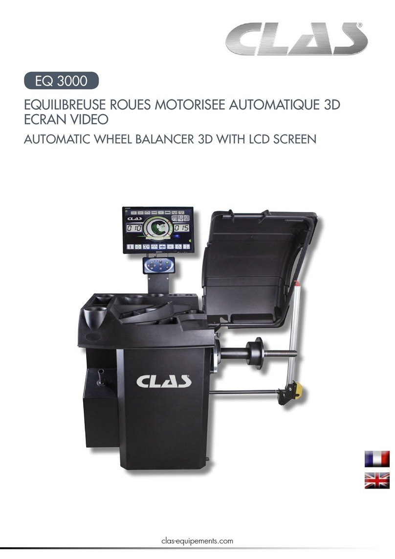
Cormach MOTO MEC User manual

WHEEL BALANCERS
MOTO MEC
USE AND MAINTENANCE
MANUAL
EN


DECLARATION OF CONFORMITY
Complies with EN ISO/IEC 17050-1 and EN ISO/IEC 17050-2
Cormach S.r.l., located in Via A. Pignedoli, 2 – 42015 Correggio (RE) – Italy,
Manufacturer of the wheel balancer line, model/s MOTO MEC
Serial Number _____________________________
Declare under our own responsibility that the product to which this declaration relates, is in conformity
with the followings Directives:
-Directive 2006/42/EC (Machinery Directive, MD)
-Directive 2004/108/EC (Electromagnetic Compatibility Directive, EMC)
The following harmonized standards have been applied:
-EN 60204-1:2006 + A1:2009
-EN ISO 11202:2010
-EN ISO 12100:2010
-EN ISO 13850:2012
-EN ISO 13857:2008
The technical file of the above mentioned machines is guarded by the manufacturer:
Cormach S.r.l., located in Via A. Pignedoli, 2 – 42015 Correggio (RE) – Italy
Correggio, 16.03.2015
IMPORTANT:
Any changes to the machine, ignoring the instructions contained in the user manual or use of the
machine other than that provided by the manufacturer, will invalidate this declaration.
The model of this declaration is in conformity with the requirements of Standard EN 45014


DICHIARAZIONE DI CONFORMITA’ RoHS
RoHS DECLARATION OF CONFORMITY
DECLARATION DE CONFORMITE RoHS
RoHS - ÜBEREINSTIMMUNG
CORMACH S.r.l. - Via A. Pignedoli, 2 - 42015 Correggio (RE) ITALY
Dichiara sotto la propria esclusiva responsabilità che il prodotto:
Declare on our own responsibility that the product:
Déclare sous son propre responsabilité que le produit:
erklärt unter ihrer eigenen Verantwortung, daß das Erzeugnis:
EQUILIBRATRICE RUOTE AUTO
EQUILIBREUSE ROUES VOITURE
WHEEL BALANCER
AUSWUCHTMASCHINE
Alla quale questa dichiarazione si riferisce, E’ CONFORME ALLA DIRETTIVA:
To which declaration refers is in CONFORMITY WITH THE FOLLOWING DIRECTIVE:
Au quel cette déclaration se rapporte EST CONFORME À LA DIRECTIVES SUIVANTES:
Darauf diese Erklärung Bezug nimmt, mit der folgenden Bestimmungen übereinstimmt:
2002/95/CE (RoHS)
Lo smaltimento della stessa e dei suoi componenti dovrà avvenire secondo quanto previsto dalla Direttiva:
Scrapping must be made in accordance with the following Directive:
La mise à la ferraille de la machine et de ses composants doit être effectuée à la conformité aux Directive suivante:
Verschrottung muß gemäß der folgenden Vorschrift durchgeführt werden:
2002/96/CE e/and/et/und 2003/108/CE (RAEE)
E le disposizioni di Legge del Paese di destinazione della macchina/apparecchiatura.
As well as with the national laws in force in the Country of Installation.
Ainsi qu’aux lois nationales en vigueur dans le Pays de destination de la machine.
sowie gemäß den in dem Installationsland geltenden Gesetzen.
Correggio, 16/03/15
Nota: per le macchine/apparecchiature immesse sul mercato dopo il 01.01.2006 anche i ricambi non originali dovranno essere
conformi alla direttiva 2002/95/CE (RoHS).
Remarks: for all machines/appliances put in the market after 01/01/2006 any spare parts, including the non-original ones, must
be in conformity with Directive 2002/95/CE (RoHS).
Note: pour les machines mises sur le marché après le 01/01/2006 toutes les pièces détachées, inclus les pièces non d’origine,
devrons se conformer à la Directive 2002/95/CE (RoHS).
Anm.: für alle Maschinen, die nach 1. Jan. 2006 in den Markt eingeführt wurden, sollen alle Ersatzteile (inkl. die Nicht-
Originalersatzteile) der Vorschrift 2002/95/CE (RoHS) entsprechen.

DICHIARAZIONE DI CONFORMITA’ RoHS
RoHS DECLARATION OF CONFORMITY
DECLARATION DE CONFORMITE RoHS
RoHS - ÜBEREINSTIMMUNG
EQUILIBRATRICE RUOTE AUTO
EQUILIBREUSE ROUES VOITURE
WHEEL BALANCER
AUSWUCHTMASCHINE
Alla quale questa dichiarazione si riferisce, E’ CONFORME ALLA DIRETTIVA:
To which declaration refers is in CONFORMITY WITH THE FOLLOWING DIRECTIVE:
Au quel cette déclaration se rapporte EST CONFORME À LA DIRECTIVES SUIVANTES:
Darauf diese Erklärung Bezug nimmt, mit der folgenden Bestimmungen übereinstimmt:
2002/96/CE e 2003/108/CE (RAEE)
La presente macchina/apparecchiatura rientra nelle prescrizioni della Direttiva 2002/96/CE e 2003/108/CE (RAEE) e non può essere smaltita come
rifiuto urbano generico ma attraverso raccolta separata; Il simbolo del bidone barrato riportato sul prodotto indica questa prescrizione. Lo
smaltimento della stessa e dei suoi componenti dovrà avvenire secondo quanto previsto dalle Direttive 2002/96/CE e 2003/108/CE (RAEE) e le
disposizioni di Legge del Paese di destinazione della macchina/apparecchiatura; il mancato rispetto della direttiva è sanzionabile secondo le
disposizioni di Legge del Paese di destinazione.
L’abbandono o smaltimento non corretto delle macchine/apparecchiature sottoposte alla Direttiva 2002/96/CE può provocare gravi danni
all’ambiente ed alle persone.
Il costruttore è disponibile, ai sensi della Direttiva, allo smaltimento della macchina/apparecchiatura; per questo servizio contattare il costruttore
o i rivenditori autorizzati secondo il Paese di destinazione della macchina/apparecchiatura.
This equipment is subject to the regulations foreseen by Directives 2002/96/CE and 2003/108/CE (RAEE) and therefore it cannot be scrapped as a
generic scrap material but through specific collection circuits; the symbol with “barred tank” marked on the product refers to this prescription.
Scrapping must be made in accordance with Directives 2002/96/CE and 2003/108/CE (RAEE) as well as with the local Regulations in force in the
Country of installation, the non-respect of the Directive is subject to sanctions according to the national Laws of the Country of destination.
Abandonment or wrong scrapping of the equipment subject to Directive 2002/96/CE can cause serious damage to the environment.
The manufacturer is available, according to the Directive, to scrap the equipment; for this service, please contact the manufacturer or your dealer.
Ce produit rentre dans les prescriptions des Directives 2002/96/CE et 2003/108/CE (RAEE) et il ne peut donc pas être mis à la ferraille comme du
matériel générique mais à travers un circuit de collecte sélective; le symbole du « bidon barré » reproduit sur la machine se réfère à cette
prescription.
Le traitement de la machine et de ses composants devra se réaliser en conformité aux Directives 2002/96/CE et 2003/108/CE (RAEE) ainsi qu’aux
dispositions de Loi en vigueur dans le Pays de destination de la machine, le non-respect de la Directive est passible de sanctions par rapport aux
Lois nationales du Pays de destination.
L’abandon ou un traitement erroné des produits sujets à la Directive 2002/96/CE peut provoquer de graves dégâts à l’environnement.
Le constructeur est disposé, aux termes de la Directive, à s’occuper du traitement de la machine; pour ce service contacter le constructeur ou les
revendeurs autorisés.
Die vorliegende Maschine/Gerät fällt in den Vorschriften der 2002/96/CE Richtlinie, und kann nicht als allgemeiner Stadtmüll sondern durch
getrennte Müllsammlung beseitigt werden; das Symbol mit der durchgestrichenen Mülltonne weist auf diese Vorschrift hin.
Die Entsorgung des Gerätes und seiner Bestandteilen muss nach den 2002/96/CE und 2003/108/CE (RAEE) Richtlinien und nach den Vorschriften
des Bestimmungslandes der Maschine/Gerätes erfolgen, die Nicht-Beachtung der Vorschrift ist sanktionierbar laut dem Gesetz des
Bestimmungslandes Die unkorrekte Entsorgung oder Verlassen der zu der 2002/96/CE vorgelegenen Richtlinie Maschine/ Gerätes kann die
Umwelt und die Personen schwer beschädigen.
Gemäß der Richtlinie, steht der Hersteller für die Entsorgung der Maschine/Gerätes zur Verfügung; dazu setzen Sie sich mit dem Hersteller oder
mit den berechtigten Händlern nach dem Bestimmungsortes der Maschine/Gerätes in Verbindung.
Correggio 16/03/15
Use and maintenance manual – 10/2016 Rev. 3Page 1
CONTENTS
1.
Introduction
Pag.
2
2.
Intended use
Pag.
2
3.
General safety rules
Pag.
3
3.1 Safety devices
Pag.
3
4.
Transport and handling
Pag.
3
5.
Unpacking
Pag.
4
6.
Installation and commissioning
Pag.
4
6.1 Installing the display head
Pag.
4
6.2 Flange for motorcycle wheel
Pag.
5
6.3 Electrical connection
Pag.
7
7.
Installation
Pag.
8
7.1 Installation area
Pag.
8
7.2 Fixing plugs
Pag.
8
8.
Suspension of the use
Pag.
9
9.
Environmental information
Pag.
9
10.
Technical data
Pag.
9
10.1 Machine dimensions
Pag.
10
10.2 Working range
Pag.
10
10.3 Presentation of the machine
Pag.
11
11.
Serial number plate information
Pag.
11
12.
Ordinary maintenance
Pag.
11
13.
Control panel
Pag.
12
13.1 Keyboard
Pag.
13
13.2 NORMAL, SERVICE, STAND BY operating modes
Pag.
14
14.
Machine calibration
Pag.
14
14.1 When to carry out machine calibration
Pag.
14
14.2 Machine calibration for the MOTO/QUAD Wheel Type
Pag.
15
15.
Use of the machine in normal mode
Pag.
17
15.1 Program Type
Pag.
18
15.2 Wheel type
Pag.
19
15.2.1 MOTO wheel type
Pag.
19
15.2.2 QUAD wheel type
Pag.
19
15.3 Entering wheel dimensions
Pag.
20
16.
Hidden weights program
Pag.
21
17.
Utility programs
Pag.
22
17.1 Selecting the imbalance display resolution
Pag.
22
17.2 Selection of the static imbalance display
Pag.
23
18.
Service mode
Pag.
23
19.
Signals
Pag.
27
19.1 Error codes
Pag.
27
19.2 Warning codes
Pag.
28
19.3 Special visual signals
Pag.
28
20.
Fire prevention means to use
Pag.
28

Use and maintenance manual – 10/2016 Rev. 3Page 2
Machine dimensions
Figure F1.1
1. INTRODUCTION
This manual is an integral part of the machine and it must to stay with wheel balancer until the scrapping of the machine.
Read carefully each section of this manual before using the machine. The manufacturer is not responsible for damage and/or injury
caused by failure to follow the instructions of this manual.
We also recommend:
•Keep the manual near wheel balancer for easy access;
•Keep the manual in a place protected from dirt;
•Do not damage the manual.
In the manual the following symbols are represented:
Indicates operations that require special attention
Indicates prohibitions
Indicates possible danger for the operator
Cormach s.r.l. We reserve the right to make any change to products in order to improve them.
Cormach s.r.l. We reserve the right to make any change to this manual without notice.
2. INTENDED USE
This manual is an integral part of product.
Read carefully warnings and instructions contained in this manual because they provide important information about SAFE USE and
MAINTENANCE.
KEEP WITH CARE THIS MANUAL NEAR THE MACHINE TO FACILITATE ANY CONSULTATION BY OPERATORS.
The wheel balancers of the range MEC are designed for balancing wheels for motorcycles (MOTO). The machines can work on wheels
with diameter from 1" to 35" (or from 25 to 890 mm) and width from 2" to 20" (or from 50 to 500 mm).
All functions and controls are set through a series of buttons arranged on a panel. The data are displayed on a led display.
420
1250
1180
640

Use and maintenance manual – 10/2016 Rev. 3Page 3
3. GENERAL SAFETY RULES
The wheel balancer must be used exclusively for the purpose it was designed for.
Any other use is considered INCORRECT and UNREASONABLE.
The use of wheel balancer is allowed only to authorized and trained personnel.
Do not put objects in the base which may affect the correct operation of wheel balancer.
THE MANUFACTURER IS NOT RESPONSIBLE FOR ANY DAMAGE TO PERSONS OR PROPERTY CAUSED BY
UNAUTHORIZED PERSONNEL OR FROM IMPROPER, INCORRECT AND UNREASONABLE USE OF THE WHEEL
BALANCER.
THE WHEEL BALANCER SHOULD NOT BE MODIFIED OR TAMPERED WITHOUT PERMISSION OF
MANUFACTURER. ANY UNAUTHORIZED MODIFICATION MADE TO THE EQUIPMENT RELIEVES THE
MANUFACTURER FROM ANY LIABILITY IN CASE OF DAMAGE ATTRIBUTABLE TO SUCH ALTERATIONS.
3.1 Safety devices
It is forbidden to tamper with, bypass or remove the safety devices installed because is a violation for the directives on safety and
health at work.
THE REMOVAL OR TAMPERING FOR THE SAFETY DEVICE IS A VIOLATION OF THE SECURITY EUROPEAN
DIRECTIVES.
4. TRANSPORT AND HANDLING
The wheel balancer is packed in a carton box on a pallet.
Transport and handling must be carried out ONLY BY AUTHORIZED PERSONNEL, with pallet truck
or forklift and adopting the appropriate safety measures.
Net weight (Kg)
Gross weight (kg)
Lenght (mm)
Width (mm)
Height (mm)
MOTO MEC
80 Kg.
95 Kg.
1180
420
1250
If the machine is not packed, observe following precautions:
PROTECT THE SHARP EDGES AT THE ENDS WITH SUITABLE MATERIAL (Bubble wrap or cardboard).
DO NOT USE METAL WIRE ROPES FOR LIFTING BOARD.
SLING WITH STRAPS OF AT LEAST 200 cm IN LENGTH AND WITH A HIGHER FLOW RATE OF 3000 kg.
DO NOT FORCE ON SHAFT AND/OR FLANGE (See figures F4.1 and F4.2).
Figure F4.1
Figure F4.2
NO
NO

Use and maintenance manual – 10/2016 Rev. 3Page 4
ALWAYS UNPLUG THE POWER SUPPLY CABLE FROM THE SOCKET BEFORE MOVING THE MACHINE.
The environmental working conditions must comply with the following requirements:
-Temperature from 0° C to + 45° C
-Relative humidity from 20% to 95%
5. UNPACKING
After removing packing, check integrity of machine making sure there are no visibly damaged parts.
In case of doubt DO NOT USE THE MACHINE and consult qualified personnel (dealer or manufacturer). The packaging materials
(plastic bags, nails, screws pieces of wood, etc.) must not be left within reach of children as they are potential sources of danger.
Packaging materials should be stored in the appropriate collection points if non-biodegradable pollutants.
CHECK THE PRESENCE OF THE BOX CONTAINING THE ACCESSORIES TO AVOID THROWING IT WITH
PACKING.
6. INSTALLATION AND COMMISSIONING
After unpacking the various parts of the wheel balancer, ensure they are intact and check for any anomalies, then assemble the parts
by following the instructions provided below.
6.1 Installing the display head
010 Unscrew nr. 4 M6 screws.
Figure F6.1
020 Fit the sheet metal rear support by running the
cables as shown in Figure F6.2 and screw no. 4 M6
screws (Figure F6.3).
Figure F6.2 Figure F6.3
030 Prepare the sheet metal front support by running
the cables as shown in F6.4.
Figure F6.4
040 Fit the sheet metal front support.
Figure F6.5 Figure F6.6

Use and maintenance manual – 10/2016 Rev. 3Page 5
050 Secure the head to the support with the M6
screws.
Figure F6.7 Figure F6.8
060 Attach the head with its CPU board to the sheet
metal front support (Figure F6.9).
Figure F6.9
070 Secure the head with no. 4 M6 screws.
Figure F6.10
6.2 Flange for motorcycle wheel
The motorcycle flange kit is provided completed as showed in
figure F6.11. Set of:
•Nr. 1 shaft Ø 14 mm
•Nr. 2 cones Ø 14.5 ÷ Ø 25.5
•Nr. 2 cones Ø 20.5 ÷ Ø 35
•Nr. 2 bushes Ø 17 + spacers
•Nr. 1 measuring adapter
•Nr. 1 calibration weight
Figure F6.11
Assembly instructions
010 Insert the pin Ø 14 mm inside the flange (Fig.
F6.12)
Figure F6.12
020 Insert the suitable screws to lock the pin (Fig.
F6.13).
Figure F6.13

Use and maintenance manual – 10/2016 Rev. 3Page 6
030 Tighten the screws to secure the pin (Fig. F6.14
and Fig. F6.15).
Figure F 6.14 Figure F6.15
040 Mount the motorcycle flange in the mechanical
unit of the wheel balance as showed in figure
F6.16.
Figure F6.16
050 The motorcycle adaptor must be mounted in the
way that the written CAL on the flange shaft and
on the motorcycle adaptor are matching and
aligned.
Figure F6.17
060 With the motorcycle adaptor leant on the shaft
tighten it with n. 2 screws supplied (Figure F6.18).
Figure F6.18
070 Mount the extension on the sensor as showed in
in figure F6.19.
Figure F6.19
080 Fit the extension on the sensor as showed in
figure F6.20.
Figure F6.20

Use and maintenance manual – 10/2016 Rev. 3Page 7
6.3 Electrical connection
The standard version of the machine must be connected to a 230V SINGLE-PHASE and 12V output power supply.
Figure F6.21
Power supply cable
The change of the power supply cannot be realized by the user; it must be requested to CORMACH s.r.l. or to a dealer or to an
authorized service center. To accomplish the electric connection, connect the machine’s power supply cable with the plug in use in
the country.
ALL OPERATIONS TO MAKE ELECTRICAL CONNECTION AND INTERVENTIONS (HOWEVER LIGHT) ON
ELECTRICAL PARTS MUST BE CARRIED OUT BY QUALIFIED PERSONNEL.
The dimensioning of electrical connection must be carried out in according to electric power absorbed by the machine. Absorption
is specified in paragraph 10. The user must:
- Check that the supply voltage correspond to the voltage indicate on the nameplate of the machine;
- Check the conditions of the wire and the presence of the ground conductor;
- Check the machine is connected to its own electrical connection, fitted with a proper 30 mA sensitive automatic circuit breaker,
against a possible electrical overload over 30 mA;
- Connect the power supply cable to the plug with great care and following to the current regulations.
WHEN THE MACHINE IS TURNED OFF FOR A LONG TIME IT IS NECESSARY TO DISCONNECT THE POWER PLUG
TO AVOID USE BY UNAUTHORIZED PERSONNEL.
IF THE MACHINE IS CONNECTED DIRECTLY TO THE POWER SUPPLY BY MEANS OF THE MAIN ELECTRICAL
BOARD AND WITHOUT THE USE OF A PLUG, INSTALL A KEY-OPERATED SWITCH TO RESTRICT THE MACHINE
USE EXCLUSIVELY TO QUALIFIED PERSONNEL.
IN CASE OF OPERATIONS ON ELECTRIC PARTS, CABLES ENGINES OR ANY ELECTRIC DEVICES, IT IS NECESSARY
TO CUT OFF THE ELECTRICITY.
DO NOT REMOVE, DAMAGE AND MAKE COMPLETELY ILLEGIBLE THE STICKERS OF DANGER, WARNING,
INSTRUCTIONS AND CAUTION. REPLACED OR DAMAGED STICKERS CAN BE FOUND AT THE NEAREST DEALER
OF MANUFACTURER.
THE DAMAGE FOR FAILURE TO COMPLY WITH THE ABOVE WRITTEN INSTRUCTIONS, IT WOULD BE NOT
CHARGED AGAINST THE MANUFACTURER AND IT MAY CAUSE THE INVALIDATION OF THE WARRANTY.

Use and maintenance manual – 10/2016 Rev. 3Page 8
7. INSTALLATION
7.1 Installation area
To install the machine you need a useful space on the basis of the information given in figure F7.1.
Figure F7.1
From working position, the user must be able to view the machine and the surrounding area.
INSTALLATION AREA MUST BE KEEP CLEAR BY POSSIBLE DANGEROUS OBJECTS.
UNAUTHORIZED PERSONNEL MUST NOT STAND NEAR BY THE WORKING AND INSTALLATION AREAS.
THE MACHINE MUST BE PLACED ON A HORIZONTAL SURFACE RATHER MADE OF CONCRETE OR TILED.
AVOID BREAKABLE AND ROUGH SURFACES.
SURFACE MUST ENDURE THE STRESS LOAD DURING THE MACHINE OPERATION.
THE MACHINE MUST BE SECURED TO THE GROUND WITH SCREWS AND EXPANSION PLUGS, ACCORDING
TO THE FOLLOWING INSTRUCTIONS.
THE USE OF THE
MACHINE IS ONLY ALLOWED IN PLACES THAT DO NOT PRESENT RISKS OF EXPLOSION OR
FIRE.
7.2 Fixing the machine to the ground
MANDATORY GROUND FIXING.
1. Drill with manual drill for a depth of 35 mm. Make no. 3 holes and then clean them.
2. Push the expansion plugs into the holes with a small hammer blows.
3. Tight the nuts with torque wrench calibrated on 23 Nm (if you are not able to achieve this value the reason could be the hole is
too wide or the concrete is not solid enough).
Figure F7.2
1000
600
600

Use and maintenance manual – 10/2016 Rev. 3Page 9
8. SUSPENSION OF THE USE
In case the machine is not used for a long time it is necessary to disconnect the power supply and protect all parts that could be
damaged by dust.
Grease all parts that could be damaged in case of oxidation. In this specific case, protect the shaft and flange.
9. ENVIRONMENTAL INFORMATION
THE DISPOSAL PROCEDURE DESCRIBED BELOW ONLY APPLIES TO MACHINES WITH
THE SYMBOL OF THE CROSSED-OUT WHEELIE BIN ON THEIR DATA PLATES.
The crossed-out wheelie bin symbol, placed on the product and on this page, reminds the user that the product must be disposed of
properly at the end of its life. This product may contain substances that can be hazardous to the environment and to human health
if it is not disposed of properly. We are therefore providing you with the information below in order to prevent these substances
from being released into the environment and to improve the use of natural resources.
Electrical and electronic equipment must never be disposed of in the usual municipal waste but must be separately collected for their
proper treatment.
Thus, the hazardous consequences that non-specific treatments of the substances contained in these products, or improper use of
parts of them, may have on the environment or on human health are prevented. Furthermore, this helps to recover, recycle and
reuse many of the materials contained in these products. Electrical and electronic manufacturers and distributors set up proper
collection and treatment systems for these products for this purpose.
At the end of the product’s working life contact your supplier for information about disposal procedures.
When you purchase this product, your supplier will also inform you that you may return another worn-out appliance to him free of
charge, provided it is of the same type and has provided the same functions as the product just purchased.
Any disposal of the product performed in a different way from that described above will be liable to the penalties provided for by the
nation regulations in force in the country where the product is disposed of.
We also ask you to adopt other environmentally-friendly measures: recycle the internal and external packaging that the product
comes in and suitably dispose of used batteries (only if contained in the product).
Your help is critical to reduce the amount of natural resources used for manufacturing electrical and electronic equipment, minimize
the use of landfills for product disposal and improve the quality of life, preventing potentially hazardous substances from being
released in the environment.
10. TECHNICAL DATA
General features
Power supply voltage
(1)
input and 12V output power supply
Balancing speed
80 RPM
Maximum displayed unbalance value
999 g.
Working resolution
X1 (1 g. or 0.1 ounces)
X5 (5 g. or 0.25 ounces)
Pin diameter
14 mm.
Working environment temperature
from 0 to +45 °C
Storage temperature
from -10 to +60 °C
Storage relative humidity
20% ÷ 95% without condensation
Machine weight (without accessories)
80 Kg
Noise level
< 70 dB(A)

Use and maintenance manual – 10/2016 Rev. 3Page 10
10.1 Machine dimensions
Depth
mm. 420
Width
mm. 640
Height
mm. 1250
10.2 Working range
Rim size manually set
mm.
inches
Rim – machine distance
2 ÷ 460
Rim width
50 ÷ 500
2.0 ÷ 20.0
Rim diameter
25 ÷ 890
1.0 ÷ 35.0
Wheel features
Maximum wheel diameter
1120 mm.
Maximum wheel width
590 mm.
Max. wheel weight
70 kg.
Machine weight (without accessories)
80 Kg.
Noise level
< 70 dB(A)
Table T10.1: Functions for machine model
Functions
MEC 1
NOTES
Data wheel manual acquisition
•
Balancing accuracy
± 0.5 g.
FMB Parking brake pedal
•
Distance gauge with extension
•
MFC Motorbike wheels calibration with zero-settings of the unbalance in the
flange
•
Static/Dynamic balancing
•
Grams/ounces selection
•
Inches/mm selection
•
Wheel programs for MOTO/QUAD ALU1, DYNAMIC and STATIC
•
STATIC program
•
DYNAMIC program
•
HIDDEN WEIGHTS program
•
STAND BY function
•
Service programs
•

Use and maintenance manual – 10/2016 Rev. 3Page 11
10.3 Presentation of the machine
1. Weight tray
2. Display/Keyboard panel
3. Mechanical group
4. MOTO flange
5. Brake pedal
Figure F10.1
11. SERIAL NUMBER PLATE INFORMATION
12. ORDINARY MAINTENANCE
To ensure the efficiency of machine and its proper functioning is essential to follow the manufacturer’s instructions by performing
periodic cleaning and routine maintenance.
CLEANING AND ORDINARY MAINTENANCE MUST BE PERFORMED BY THE AUTHORIZED PERSONNEL IN
ACCORDANCE WITH THE MANUFACTURER INSTRUCTIONS PROVIDED BELOW.
Always keep the flanges clean (non-lubricated). In addition, during the handling, pay the best attention to not damage them.
For cleaning the machine, especially for the weight-tray, use a soft cloth moistened with ethyl alcohol.
EVERY OPERATION MUST BE DONE ONLY AFTER THE CABLE HAS BEEN DISCONNECTED FROM ITS POWER
SUPPLIER.
DO NOT BLOW COMPRESSED AIR TO CLEAN THE MACHINE AND LASER POINTER.
DO NOT USE WATER OR OTHER LIQUIDS FOR CLEANING THE MACHINE.
4
1
3
2
5

Use and maintenance manual – 10/2016 Rev. 3Page 12
13. CONTROL PANEL
The machine control panel is shown in Figure F13.1. The control panel allows the operator to give commands and enter or edit data.
The same control panel displays the balancing results and machine messages. The functions of the various parts of the control panel
are described in table T13.1. The control panel is provided on the rear with an electronic control board collecting, processing and
displaying data.
Figure F13.1: Control panel
Table T13.1: Functions of different parts of the control panel
Pos.
Description
1 – 5
Display to show inside/outside imbalance value.
2 – 4
Light indicator showing inside/outside imbalance angular position.
3 Imbalance Weight Position light indicator. Group of 5 LEDS (red). Position depends by the Program and Wheel Type
selected.
6
"F" key to access the secondary function of the keys (P7).
7
STATIC program selection key (P10).
8
ALU program selection button (P8).
9
MOTO/QUAD selected Wheel Type light indicator (red).
10 Light indicator of the selected unit of measurement: inches/mm. Group of two light (red) indicators to indicate the
selected unit of measurement.
11
Charging indicator light with battery (Optional).
12 Selected Program Type light indicator (STANDARD/ALU/STATIC). Group of 3 light (red) indicators to indicate the selected
Program Type.
13 Example of standard key: it has a main function (big icon shown inside the key) and a secondary function (small icon
shown outside the key).
14
Active stand-by light indicator.
13
3
2
1
4
5
6
7
8
9
10
11
12
14

Use and maintenance manual – 10/2016 Rev. 3Page 13
13.1 Keyboard
For your convenience, the keys in this manual are numbered from [P1] to [P10] as shown in Figure F13.1. Next to the reference
numbers of the keys, there are icons of the keys themselves for easy reading. The ten buttons have a main function indicated by a
symbol in the levelled square, and a secondary function indicated by a small icon located nearby. Some of the secondary functions
feature an LED to indicate their activation. The keys [P7] , [P8] , and [P10] do not have a secondary function.
The secondary function of the keys is identified in this manual with the codes from [F+P1] to [F+P9] as shown in Figure F13.3.
Figure F13.2: Key example showing the main and secondary function
To enter the secondary function of a key, press the [P7] then, by holding it down, press one of the keys for which a secondary
function is desired; then release both keys.
Figure F13.3: Key secondary functions numbering
Table T13.2: Settings, programs and menus available in SERVICE mode
SERVICE mode
Key
Setting/Program or Menu
Key
Setting/Program or Menu
[P1]
Not used
[F+P1]
Not used
[P2]
Not used
[F+P2]
Not used
[P3] Machine calibration [F+P3] Exit SERVICE mode
(return to the NORMAL mode)
[P4]
Grams/ounces selection
[F+P4]
Read counter with the number of launches
[P5] Inches/mm selection [F+P5] Parameters (Menu with password reserved for
technical service)
[P6]
Imbalance threshold view selection
[F+P6]
Not used
[P9]
Not used
[F+ P9]
Testing programs
Note: The [P7] , [P8] ALU and [P10] STATIC keys are not used to access settings, programs and menus.
Key first function
This is the sensitive part that must
be pressed.
Key secondary function.
This section contains only a graphic
indication. An LED indicates when the
secondary function is active.
[F+P1]
[F+P4]
[F+P5]
[F+P6]
[F+P9]
[F+P2]
[F+P3]

Use and maintenance manual – 10/2016 Rev. 3Page 14
13.2 STANDARD, SERVICE, STAND-BY operating modes
The machine features three operating modes:
•STANDARD mode. This mode is enabled after the machine is turned on and it is possible to perform the wheels balancing;
•SERVICE mode. In this mode various utility programs are available for setting parameters (such as grams or ounces) or
checking the machine operations (such calibration);
•STAND-BY mode. After 5 minutes of inactivity, the machine will automatically go into STANDBY mode to reduce power
consumption. The STAND-BY green LED on the control panel flashes when the machine is in this operating mode. All
acquired data and settings are held in STAND-BY mode. In the SERVICE mode is not possible to switch to STAND-BY mode.
To exit from STAND-BY mode choose by any of the following means:
Press any key (with the exception of [P7] );
Rotate manually the motorcycle flange so that the wheel will turn counterclockwise (Figure
13.4).
Figure 13.4: Action on motorcycle flange
Note: The machine will exit STAND-BY mode also by pressing the [P8] ALU key.
14. MACHINE CALIBRATION
To function properly, the machine must be calibrated. Calibration allows storing the mechanical and electrical parameters specific to
each machine so as to provide the best balancing results.
14.1 When to carry out machine calibration
Table T14.1 lists the cases in which machine calibration should be carried out. Calibration must be carried out whenever one or more
of the conditions listed are active.
Table T14.1: Conditions for carrying out machine calibration
Condition
Status
Who must perform it
When the machine is installed at the final user's site
Mandatory
Technical Service
When the electronic circuit board is replaced
Mandatory
Technical Service
When a mechanical part linked to the pick-up signal
(pick-up, pick-up compression
springs, suspension
unit + shaft) is replaced
Mandatory Technical Service
When the pick-up compression spring adjustment is
modified
Mandatory Technical Service
When the encoder disc is replaced
Mandatory
Technical Service
When the machine does not
provide the best
balancing results
Recommended Final user and/or Technical Service
When there are large, constant variations in the
environmental humidity and temperature conditions
(for example seasonal changes)
Recommended Final user and/or Technical Service
Table of contents
Other Cormach Wheel Balancer manuals

Cormach
Cormach MEC 200 TRUCK User manual

Cormach
Cormach TOUCH MEC 1000 SONAR Installation instructions

Cormach
Cormach MEC 810VD-VDL-VDBL User manual

Cormach
Cormach GEO 15 User manual

Cormach
Cormach GEO 15 User manual

Cormach
Cormach MEC 1 Installation instructions

Cormach
Cormach TOUCH MEC 100 User manual

Cormach
Cormach MEC 5 Installation instructions

Cormach
Cormach GEO 10 User manual
Popular Wheel Balancer manuals by other brands

Snap-On
Snap-On WBM250 user manual

Atlas Equipment
Atlas Equipment WBT-210 Installation & operation manual

HENNESSY INDUSTRIES
HENNESSY INDUSTRIES coats 525 operating instructions

Ranger
Ranger Laser-Spot LS43B Installation and operation manual

ATH-Heinl
ATH-Heinl ATH W82 user manual

Weaver
Weaver W-987 manual