Brightline Stealth-T Quick start guide

Stealth-T Videoconference Fixture
230V Operation and Installation Guide
Evolutionary Lighting Systems
580 Mayer Street, Building #7, Bridgeville, PA 15017 • phone: 412.206.0106 • fax: 412.206.0146
www.brightlines.com
© 2011 Brightline L.P. All rights reserved. Patent pending.
TM
REV 11/17/2011
1

2
Model No.________________________
Serial No.________________________
Date of Purchase__________________
• The serial number of this product can be found on the top of the ballast cover. You should note
the model number and the serial number in the space provided and retain this book for future
reference as a permanent record of your purchase.
Safety
Owner’s Record
Product Description
• Fixture installation should be performed in accordance with local and national codes. All fixtures must be
properly grounded.
• To prevent fire or electric shock, do not expose the fixtures to water or moisture. Stealth-T fixtures are listed for
indoor use only.
• Do not attempt to dim a non-dim fixture. Do not attempt to operate a fixture without lamps installed, as this
could damage the ballast.
• Do not attempt to change the lamps on a fixture that is energized, or to work with your hands near an exposed
socket that is energized.
• A qualified technician should perform service on fixtures. Do not remove the ballast cover until the unit has
been de-energized.
• In case of lamp failure:
1. Turn the fixture power off.
2. Wait 30 seconds for the ballast to reset.
3. Install the new lamp(s).
4. Turn the fixture back on.
Stealth-T Fixtures
Two-lamp, glare-free videoconference lighting fixtures, ideal
for distance-learning and telepresence applications. Available
with four louver types: Forward Throw, Corner Throw, Bidirectional
Throw, or Downward Throw. Multiple ballast types available.
Forward-Throw Louvers
Corner-Throw Louvers Bidirectional-Throw Louvers Downward-Throw Louvers
Brightline fixtures are not Insulated Ceiling (IC) rated. Maintain the proper distance from insulation.Brightline fixtures are not Insulated Ceiling (IC) rated. Maintain the proper distance from insulation.
• Brightline fixtures are not Insulated Ceiling (IC) rated. Maintain the proper distance from insulation.

3
Specifications
Lamp: 55W/DL
3000 K - 82 CRI, 10,000 hours
3000 K - 96 CRI, 10,000 hours
3500 K - 82 CRI, 10,000 hours
4100 K - 82 CRI, 10,000 hours
Studioline
3200 K - 85 CRI, 8,000 Hours
5600 K - 85 CRI, 8,000 Hours
Lamp Socket:
2G11 4-pin. Molded white high-strength thermoplastic. Push-wire connections for 18-gauge leads.
Finish:
Fixture body is painted with high-gloss, electrostatically applied white enamel finish.
Louver and door frame are painted with matte white enamel.
Optional Accessories:
Louvers are available for angled operation (approx. 45º) in one direction (FW and CA options) or
bidirectionally (BI option). Louvers are also available for downward-throw operation (DN option).
Reflector:
Die-cut, code-gauge, cold-rolled steel with (4) pull-down spring latches. Door frame may be
removed from fixture without tools.
Luminaire/Ballast:
High-frequency electronic ballast with a power factor > .97, THD < 10%. Class A sound rating.
Luminaire operates at 230VAC, 50 Hz., .51A
Dimensions:
The overall dimension of the fixture body (with the exception of the door frame) is
23.4- x 23.4- x 4.8-in [595- x 595- x 122-mm]. The approximate weight of the fixture is 18 lb [8.2 kg].
Housing:
Die-formed, code-gauge, cold-rolled steel housing. Aluminum louvers. Fixture may be used in
a 24-in or 600mm lay-in grid ceiling or cut into drywall or plaster. Thin-flange grids may require a flange kit.
Labels:
CE approved; patent pending; IP20

4
1. Unpack the fixtures. The louver frames and lamps may be packed with the fixtures or separately.
To prevent damage, install the fixtures before installing lamps and louver frames.
2. Prepare the line-voltage wiring to the fixtures. Depending on building conditions, it may be necessary
to install the power and control wiring before the fixture is placed in the ceiling. Ensure that the supply
voltage matches that required by the ballasts. To install the power feed, remove the knockouts as needed
and install the correct type of power cabling and strain relief (not provided). Connect the wires from the
feed using wire nuts, observing the wire color-coding, and re-install the knockout plate. Brightline
fixtures intended for the North American market use Black/White/Green wires respectively for
Line/Neutral/Earth Ground; fixtures shipped to other locations use Brown/Blue/Green-Yellow for
Line/Neutral/Earth Ground. You may want to install sufficient slack in the power cable so that, if
necessary, the fixture can be moved to an adjacent ceiling opening.
3. These fixtures are not Insulated Ceiling (IC) rated. Maintain the proper distance from insulation
(3 in [76 mm] in the US and Canada).
4. If the fixture requires low-voltage control, the proper wiring must be run to each fixture. Connect the
control wires inside the fixture, observing the proper color-coding. Install the control wiring
above the ceiling. (See the Control Wiring section below.)
5. Fixtures can be mounted in two ways: either flush-mount in a “hard” ceiling, such as plaster or drywall;
or mounted in a T-Grid acoustical-tile ceiling.
Installation
Figure 3
Figure 1
Figure 2
• Hard Ceilings: Verify that the locations in which you
intend to mount the fixtures are free of above-ceiling
obstructions such as ceiling joists, air conditioning
ducts, etc. For ease of installation, a minimum of
8 in [203 mm] of clear height above the ceiling is
recommended. In accordance with drawings provided
by Brightline or the local architect or engineer, prepare
the ceiling by cutting openings that are 24.56- x 24.56-in
[624- x 624-mm] in size. Depending on ceiling construction,
it may be necessary to install a frame in the opening to
accommodate the weight of the fixture. Install the power and
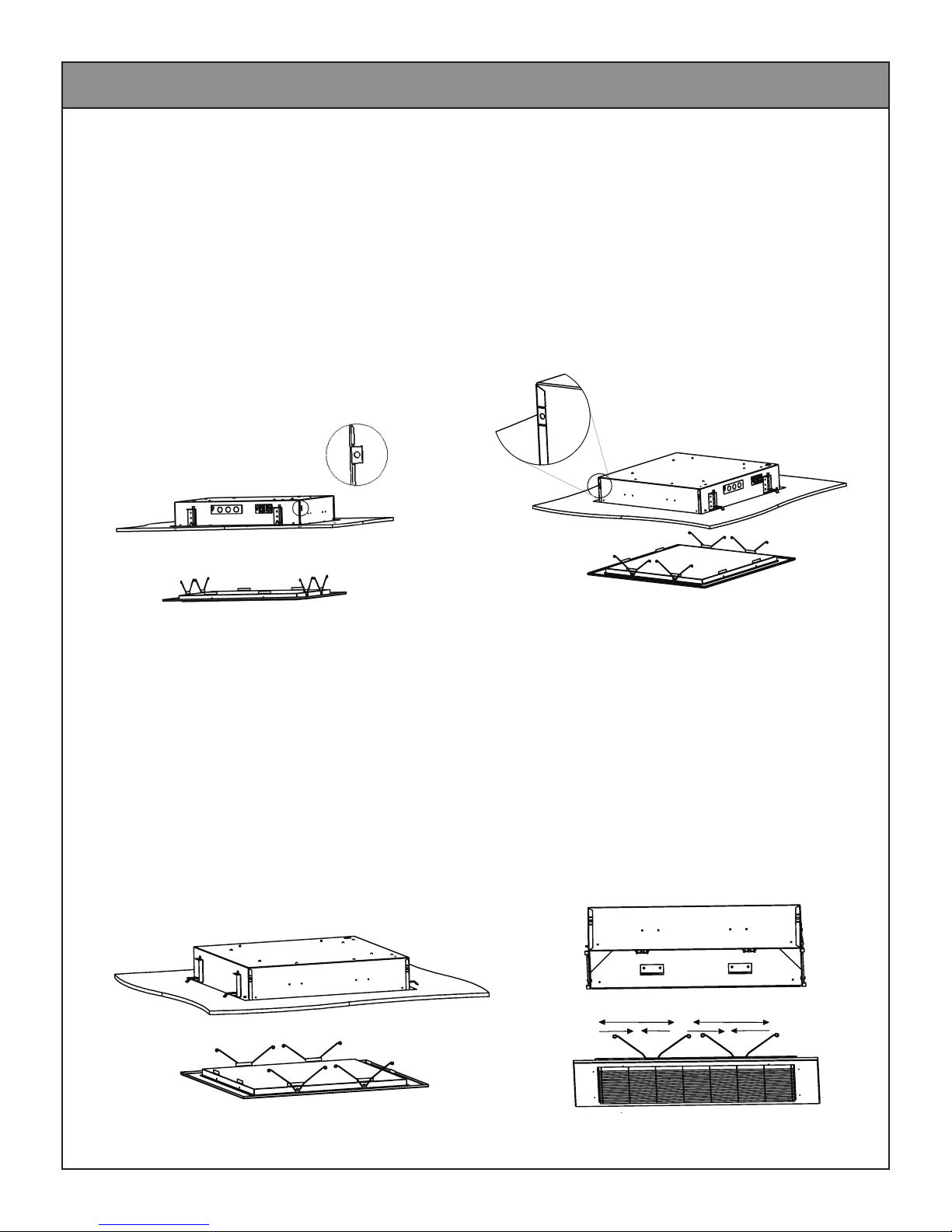
control wiring as described above. With the mounting clips
in their recessed position (folded back next to the fixture,
see figure 1), lift the fixture into its opening.
Using a screwdriver, turn the screws on the bottom of the mounting clips until the clips turn approximately
90° and rest on the frame or ceiling structure. (Figure 2) Adjust the clips so the bottom of the fixture is
flush with the exposed side of the ceiling. (Figure 3)

5
Installation
6. If necessary, complete the installation of the power and control wiring
7. With the power off, install the lamps. Make sure they are firmly seated in their sockets and clips.
8. Energize the fixtures and test for proper operation.
9. Install the door frame and louver assembly, with the openings in the louvers pointed in the correct
direction(s) as indicated on the project drawings. (Figure 6 and 7)
10. For optimal performance, Season lamps for 12 hours prior to dimming.
Note: Approximate initial Lumens after 100 hours of operation.
Figure 6
Figure 7
Figure 5Figure 4
8. Energize the fixtures and test for proper operation.
5A. Install “safety wires” on the tabs on the sides of the fixtures and attach to the building structure,
in compliance with local codes. (Figures 4 and 5) Brightline recommends not relying on the t-track
alone to hold the weight of the fixtures.
5. (continued)
• T-Grid Ceilings: Prepare the T-Grid to receive the fixtures. Fixtures are available for either 2- x 2-ft or
600- x 600-mm grid spacings. Depending on the ceiling layout, it may be necessary to add additional track
sections and/or prepare different sized ceiling tiles. For ease of installation, a minimum of 8 in (200 mm)
of clear height above the track is recommended. Make sure that the T-Grid is sufficiently braced to accept
the weight of the fixtures. Place the fixtures into the correct openings in the ceiling grid in accordance with
plans provided by Brightline or the local architect or engineer. If required by local code, install “safety clips”
to attach the fixtures to the T-Grid or the building structure.
Note: Use screwdriver to bend tabs outward to install safety wires.

6
Non-Dim (Switched) Riser Diagram
LL
L L
L
L
L Line Voltage
The fixture is wired to a source of AC power (Line/Neutral/Ground) only.

7
Phase-Control (Two-Wire) Riser Diagram
Electrical installation:
Brightline provides a sealable power bracket with a
3-pole terminal block on its interior face and a
power inlet for cord up to 15mm. To wire the
fixture:
1. Untighten self-tapping screw
2. Remove bracket from fixture enough to
access terminal block
3. Feed leads through the grommetted hole
4. Wire according to label adjacent to
terminal block. Tighten contact screws
5. Re-insert bracket into fixture and close
with self-tapping screw

8
Label Placement Reference
brightline
R
MODEL: ST2X2-24FW-IG
230VAC, 50Hz., .51 AMPS
USE MINIMUM 90
C SUPPLY CONDUCTORS
•
DO NOT INSTALL INSULATION WITHIN 76MM
•
(3 IN.) OF ANY PART OF THE LUMINAIRE
DRY LOCATIONS ONLY
•
IP RATING: IP20
TURN OFF FIXTURE BEFORE RELAMPING
•
CAUTION: RISK OF FIRE - USE WITH MAXIMUM 55 WATT LAMP (BIAX, 2G11 SOCKET)
•
AMBIENT TEMPERATURE (T
a
): 25
C
•
INPUT VOLTAGE
GROUND (EARTHLING)
INTERIOR FACE OF BRACKET

9
Page left blank intentionally

10
Digital-Dimmed (DALI with Wall Controller) Riser Diagram
DALI Dimmed
A DALI (Digital Addressable Lighting Interface) signal controls these fixtures. The fixtures will function (but not dim) in
the absence of a control signal.
The control signal is connected to the fixture through the 3-pin XLR-type receptacle on the side of the unit. As this is
low-voltage wiring, it may not be necessary to install the control wiring conduit. If they were specified, the DALI
control cables may be provided as part of your order. Two receptacles are provided to allow the control wiring to be
daisy-chained.
As each fixture is assigned an individual address, fixtures on a DALI control line may be dimmed to differing
intensities.
DALI control wiring is topology and polarity independant. DALI control cables may be daisy chainned. Keep the total
wire run as short as possible. See the literature that is provided with your DALI controller, or contact Brightline for details.
Power for the DALI network is provided by a seperate power supply. See the instructions that come with it for
installtion instructions.
For clarity, only one fixture’s power feed is shown. Each fixture requires a source of unswitched AC power.
L

11
Digital-Dimmed (DALI with RS-232 Busmaster) Riser Diagram
DALI Dimmed with BusMaster
A DALI (Digital Addressable Lighting Interface) signal controls these fixtures. The fixtures will function (but not dim) in
the absence of a control signal.
The control signal is connected to the fixture through the 3-pin XLR-type receptacle on the side of the unit. As this is
low-voltage wiring, it may not be necessary to install the control wiring in conduit. If they were specified, the DALI
control cables may be provided as part of your order. Two receptacles are provided to allow the control wiring to be
daisy-chained.
As each fixture is assigned an individual address, fixtures on a DALI control line may be dimmed to differing
intensities.
DALI control wiring is topology and polarity independent. DALI control cables may be daisy-chained. Keep the total
wire run as short as possible. See the literature that is provided with your DALI controller, or contact Brightline for details.
Power for the DALI Network is provided by the BusMaster. The BusMaster and the DALI network are configured by using
the supplied WinDIM software. The BusMaster may optionally be controlled by an A/V proccessor via its RS-232
serial interface.
For clarity only one fixture’s power feed is shown. Each fixture requires a source of unswitched AC power.
L Line Voltage
L

12
Troubleshooting Guide
Maintenance
• The fluorescent lamps provided with the fixtures are rated for up to 10,000 hours. However, as with all
lamps, there will be some drop-off in intensity as they approach their rated life. A conservative user may
want to re-lamp at 75-80% of the rated life. Brightline recommends that as lamp intensity begins to
drop off, or when the life expectancy is reached, all lamps in a room be replaced as a group.
• The lamps provided with your Brightline fixture have been selected to provide the correct operating
parameters for your video system. All lamps should be replaced with those having an identical model
number and manufacturer. After relamping, it may be necessary to perform a new white-balance on your
camera(s) after re-lamping. Contact your Brightline dealer or representative if you need assistance
in purchasing replacement lamps.
• Dispose of used fluorescent lamps in conformance with local regulations or by participating in Brightline’s
lamp-recycling program.
• For optimal fixture performance, it is necessary to keep the lamps and lenses clean. Use a dry, non-abrasive
cloth to remove dust. Avoid the use of materials that might scratch the lenses.
noituloSesuaCelbissoPmelborP
Fixture does not light. 1. Missing or improper incoming power.
2. Defective lamp(s)
1.Verify that the fixture is recieving proper voltage.
2. Troubleshoot by replacing with known good
lamps. If necessary, replace with new lamps.
Lights go to full but do not
dim to minimum.
1. Ballasts are not properly grounded.
2. Lamps are too old.
3. Improper control signal.
1. Check to see that the fixture is properly grounded.
2. Relamp the entire fixture.
3. If yours is a low-voltage-controlled fixture, the control signal
may be missing or the fixture may not be properly configured.
Lights flicker or drop out at
low end.
Defective or damaged lamps. Test with lamps from a known good fixture; replace
bad lamps as required.
Lights are flashing or
strobing.
Wrong voltage for ballast installed. Verify that the supply voltage is correct for
ballast installed.
Lamps are not at the same
light level.
Check that all the lamps are of the same
type and age.
Mixture of lamp ages or color temperatures.
Ballast buzzes or hums. Defective ballast.Indentify location of buzz and replace ballast if
necessary.

13
DISCLAIMERS
Brightline guarantees all its products to be free from defects in materials and
workmanship for a period of one (1) year from the date of shipment.
If any product is found to be unsatisfactory under this warranty, the buyer must notify
Brightline immediately. Once a course of action has been determined, if it is neces-
sary to return the product to Brightline a Return Authorization (RA) will be issued.
Ship the product directly to Brightline, 580 Mayer Street, Building #7, Bridgeville, PA
15017. The RA number should be marked on the shipping carton. The unit will be
replaced or put into proper operating condition, free of all charges. The correction of
any defects through repair or replacement by Brightline shall constitute fulfillment of
all obligations and liability of Brightline to the buyer under this warranty and the
contract of sale.
Brightline is not responsible for damage to its products caused by improper
installation, maintenance, or use; by improper electrical hookups; or by unauthorized
repairs.
Failure to notify Brightline of unsatisfactory operation or any improper or
unauthorized installation, maintenance, use, repairs, or adjustments shall terminate the
warranty and Brightline shall have no further responsibility under the warranty.
Brightline shall not be liable for special or consequential damages in any claim,
action, suit, or proceeding arising under this warranty or contract of sale, nor shall
Brightline be liable for claims for labor, loss of profits or goodwill, repairs, or other
expenses incidental to replacement. Brightline makes no other warranty of any kind
whatsoever, expressed or implied, and all implied warranties of merchantability and
fitness for a particular purpose that exceed the obligation specifically described in this
warranty are hereby disclaimed by Brightline and excluded from this agreement.
All shipments, unless otherwise noted, are F.O.B. factory.
The customer is advised to inspect for shipping damage, apparent and/or hidden.
If detected, notify the transportation company and file your claim.
WARRANTY
PROCEDURES
580 Mayer Street, Building #7, Bridgeville, PA 15017 •phone 412.206.0106 •fax 412.206.0146
www.brightlines.com

14
Notes
Table of contents
Other Brightline Conference System manuals
Popular Conference System manuals by other brands

Kindermann
Kindermann K-FX Base Unit quick start guide

AT&T
AT&T Partner Plus Installation and programming guide

Ocean Reef
Ocean Reef ALPHA-PR0 X-DIVERS owner's manual

AVer
AVer SVC100 user manual

scope
scope DL4ACLUSA Installation & user manual

Califone
Califone AV Tutor Fundamentals Center 2056 Specifications