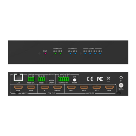
Brightlink BL-VW22-4K30 User manual

1
BRIGHTLINK HDMI 2X2 4K Video Wall Controller
with Mixed inputs
MODEL : BL-VW22-4K30
Operating Instruction
BRIGHTLINKAV.COM

2
Directory
1. FEATURES.....................................................................................................................................3
2. NOTICE.......................................................................................................................................... 3
3. SPECIFICATIONS.........................................................................................................................3
4. PACKING CONTENTS................................................................................................................. 4
5. PANEL DESCRIPTIONS...............................................................................................................4
6. CONNECTING AND OPERATING..............................................................................................4
7. Remote Control Instruction............................................................................................................5
7.1 Video switching operation.......................................................................................................5
7.2 Video control.......................................................................................................................... 6
7.3 EDID setup interface.............................................................................................................12
7.4 Audio control........................................................................................................................ 12
7.5 Setup interface.......................................................................................................................14
7.6 INFO query information interface......................................................................................... 21
7.7 Basic information interface....................................................................................................22
8. Web Control.................................................................................................................................. 22
8.1 Interface Introduction............................................................................................................24
8.2 Login Test.............................................................................................................................24
8.3 Splicing interface.................................................................................................................. 25
8.4 Mirror interface.....................................................................................................................26
8.5 Edge interface....................................................................................................................... 27
8.6 Menu interface...................................................................................................................... 27
8.7 EDID interface......................................................................................................................28
8.8 Network interface..................................................................................................................29
8.9 System interface....................................................................................................................29
9. RS232.............................................................................................................................................30
10. Audio............................................................................................................................................31
10.1 HDMI audio output.............................................................................................................31
10.2 Audio separation output.......................................................................................................31
11. Firmware upgrade.......................................................................................................................32
11.1 MCU burn...........................................................................................................................32
11.2 GUI burn.............................................................................................................................32
12. CONNECTION DIAGRAM.......................................................................................................32
MAINTENANCE..............................................................................................................................34

3
1. FEATURES
lSupport Type C/DP port/HDMI input.
lSelect 1 of 4 source and distribute to 4 displays.
lCreate a 2x2 Video Wall Controller from any source to four displays.
lSupport multi-level cascading to create 3x3, 4x4...Video Wall (Max 10x10).
lSupport 180° rotation.
lSupport resolution up to 4K30HZ.
lSupport EDID management:Two default EDID: 4K30HZ, 1080P;user can copy
the EDID of the loop out and any output port.
lSupport HDCP2.2/1.4
lWith panel button, Remote Control, RS232 Control, TCP/IP Control to select the
source.And support for third-party platform control.
2. NOTICE
Our company reserve the right to make changes in the hardware, packaging and any
accompanying documentation without prior written notice.
3. SPECIFICATIONS
Operating Temperature Range 0 to +40°C (32 to +104°F)
Operating Humidity Range 10% to 90 % RH (no condensation)
Output Video Format Supported 1080P60/720P60/
1920X1200/1366X768/4K30HZ
Supported input resolution
The maximum input resolution supported by HDMI is
3840x2160@60hz.
The maximum input resolution supported by DP is
4K30
Transmission distance
Input: maximum---3 m
Output: 4K/30Hz---10 m
1080P/60Hz: maximum---15 m
Audio Format Supported LPCM
Input ports 2xHDMI, 1xDP, 1xType C
Output ports 5xHDMI
Splitter mode 1x4 HDMI Splitter
Video wall mode 2x2,3x3,4x4......10x10 video wall
Control Way Panel control, IR control, RS232 control
Power consumption 15watts(Maximun)
Dimension (mm) L438XW191.2XH44 mm
Weight 2460g

4
4. PACKING CONTENTS
1) Main Unit: HDMI 2X2 4K Video Wall Controller
2) 1x Power supply 12V2A
3) 4x Screws
4) 2x detachable mounting ears
5) 1x IR Cable
6) 1x Remote controller
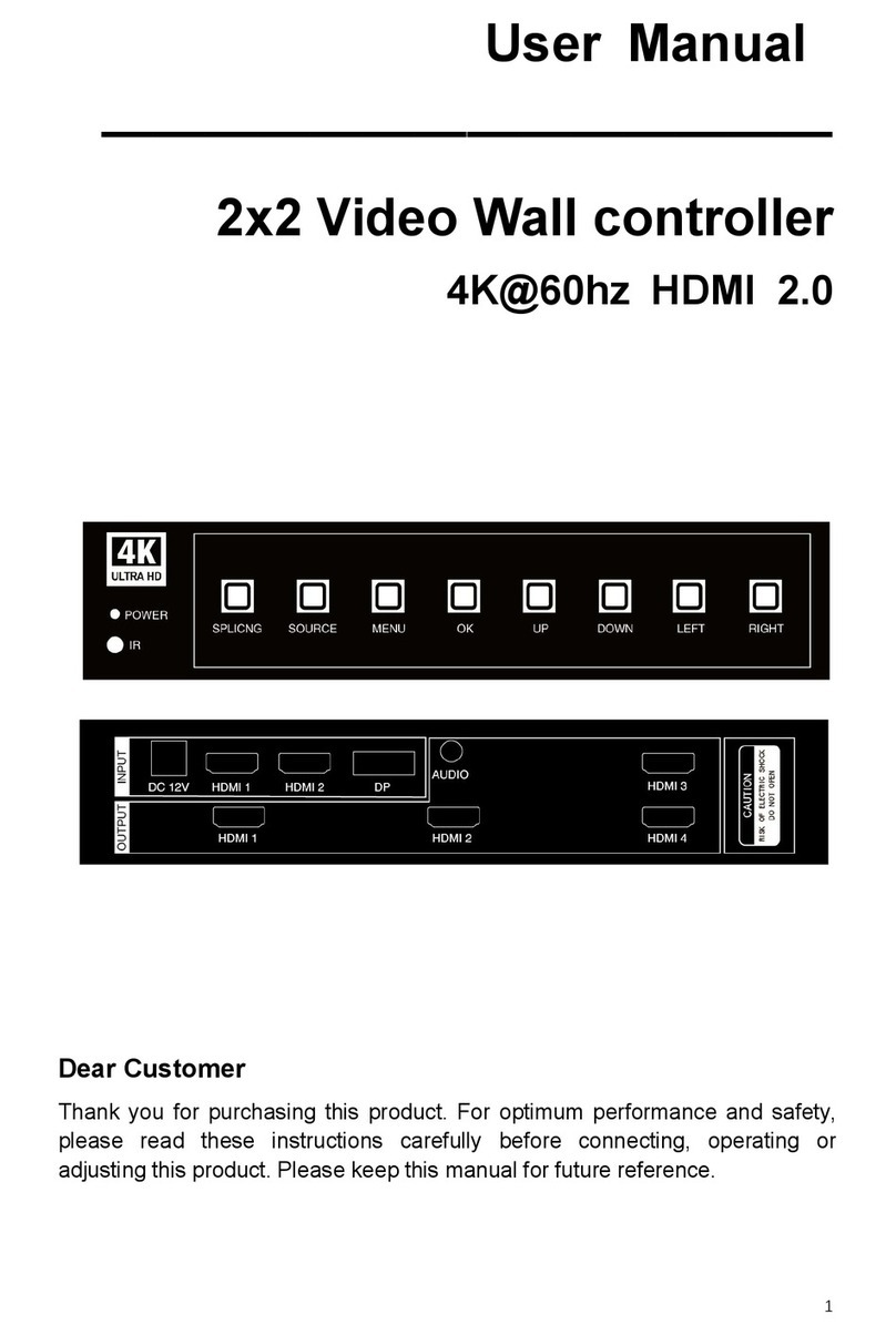
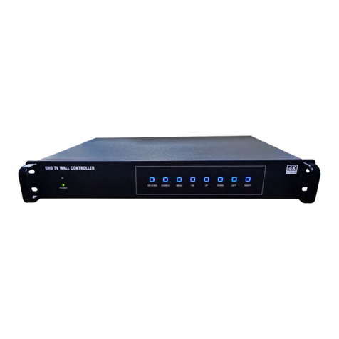
5. PANEL DESCRIPTIONS
Front Panel
1. Input status light
2. Buttons (Input; Up; Down; Left/Menu; Right/Enter)
3. Firmware port
4. IR
5. Power button
Noted:Press the Left/Menu and Right/Enter button together for 5 seconds to reset the
system;Long press the UP and DOWN button,The device will loop through the output
resolution RearPanel
1. Power input port
2. RS232 & IP Control
3. HDMI Inputs (Type-C, DP, 2x HDMI in)
4. HDMI Outputs (HDMI Loop, SPDIF, Audio, 4x HDMI out)
6. CONNECTING AND OPERATING
1) Connect the sources into the video wall controller and Press the button on the
remote to choose the input Signal (DP, 2XHDMI, USB,Type C ).
2) Connect HDMI OUT to display equipment.

5
3) Power up the Video Wall Controller.
4) Control the Video Wall Controller by Panel button / Remote /
RS232 Command.
7. Remote Control Instruction
1. Power on/off
2. Mute
3. Source switching
4. Switch signal source of IN1
(TYPE C)
5. Switch signal source of IN2 (DP)
6. Switch signal source of IN4
(HDMI 2)
7. Switch signal source of IN3
(HDMI 1)
8. Menu
9. ▲:UP ▼:Down ◄:Left/Menu
►:Right/Enter OK:Right/Enter
10. Display and hide OSD menu
11. Return to menu interface
12. 1-4: select the input source
IN1---IN4
Note 1: Right/Enter means that when you select to the Right ,you are applying
the functionality of the option on the Righ
7.1 Video switching operation
The OSD display interface of video switching only shows four output channels and
the current input signal channels, and can only switch one input signal to all output
channels (in the case of input and output access).

6
Video switching interface
Operation mode: press the "INPUT" button directly and cycle through the input signal
7.2 Video control
Press "Left/Menu" on the panel to enter the main menu.
Main menu interface
The function of the main menu is:
1. switching video signal source
2. EDID settings
3. Audio settings
4. Setup parameter settings.
5. INFO query
Note: the number 1/ 5 represents the first subitem of the five projects
Operation Description: Use the” up and down” to select ,the “Left/ Menu” button to
return to the previous projects, and “Right/ Enter” to confirm the option
Video includes five subitem:Switching, Splicing, Mirror, Edge Set, Format.
7.2.1.Video switching

7
Any input signal can be switched to all outputs. The signal switching includes four
input signals, In1 is TYPE C input, In2 is DP input, In3 is HDMI 1 signal, In4 is
HDMI 2 signal. It is the default HDMI IN1 input.
Operation steps:
1. In the main menu, select "Video" to press the "ENTER" button to confirm.
2. Press the “up and down” button to select Switching.
3. Click the "ENTER" button to enter the next sub-item
4. Press the “up and down” button to select the "In" input port, the bottom color of
the selected input port becomes red, and the @ (Selected Symbol) is displayed
5. Click the "ENTER" button to confirm that the video switch is complete
7.2.2.Wall pattern
It can perform fixed video wall or cascade video wall Settings on the output video,
which has two setting options in this mode:
Preset: it can set up some fixed preset video wall scenarios, default to 1×1
Operational steps:
1. In the main menu, select "Video" to press the "ENTER" button to confirm
2. Press the “up and down” button to select 'Splicing'
3. Click the "ENTER" button to enter the next sub-item

8
4. Press the “up and down” button to select the "Preset" setting option, the bottom color of
the selected input port becomes red, and the @ (Selected Symbol) is displayed.
5. Click on the "ENTER" button to confirm and go to the next submenu
6. Press the “up and down “button to select "1 x 1" and other fixed preset video wall mode,
7. Click on the "ENTER" button to set up the video wall mode successfully
Set Up: H_NUM represents the total number of screens on the horizontal axis, with 1 x 10
selections, the default is 1.
V_NUM represents the total number of screens on the vertical axis, with 1 x 10 selections, which
defaults to 1.
Cascade indicates where the device is in the cascade, with options 1-25, which defaults to 1.

9
Operational steps:
1In the main menu, select "Video" to press the "ENTER" button
2Press the “up and down” button to select 'Splicing'
3Click the "ENTER" button to enter the next sub-item
4Press the “up and down”button to select the "Set Up" setting option, and the bottom color of
the selected setting option turns red
5Click on the "ENTER" button to confirm and go to the next submenu
6Press the”up and down”button to select "H_NUM",
7Click on the "ENTER" key to enter the next subitem
8Press the”up and down”button to select the number of "1" and select the number of screens
to set
9Click the "ENTER" button, the number of horizontal axis display set successfully.
10 Set up the number of vertical display screens with the above steps, and what level is the
cascade
7.2.3. Mirror mode
All output video can be mirrored, which includes four options: Normal---default mode
(do not mirror), Only X---horizontal mirror, Only Y---vertical mirror, X and Y
horizontal and vertical mirror (that is, 180 degrees rotation);

10
Operational steps:
1. In the main menu, select "Video" to press the "ENTER" button
2. Press the”up and down”button to select Mirror
3. Click the "ENTER" button to enter the next sub-item
4. Press the “up and down” button to select settings such as "Normal", and the
bottom color of the selected setting options becomes red
5. click on the "ENTER" button to confirm that the mirror processing settings are
successful
7.2.4.Margin setting
You can set the margins of the output image, including two subitems:
X: the margin setting between the two horizontal displays is set with the 0~600 option,
with a minimum unit of 2.
Y:vertical two screen in the middle of the margin settings, there are 0~600 options
to set, the minimum unit of 2.
The middle margin of horizontal and vertical display screen defaults to 0;
Operational steps:
1.In the main menu, select "Video" to press the "ENTER"button
2.Press the “up and down” button to select "Edge Set"
3.Click the "ENTER"button to enter the next sub-item
4.Press the “up and down” button to select the "X" setting option, click the
"ENTER" button to enter the next subitem.Click the “up and down”button select and

11
set the margin between the two horizontal displays as required, and click the
"ENTER" button to complete the setting
5.press the "Left/Menu" button to return to the previous menu, press the “up
and down”button to select the "Y" setting option, click the "ENTER" button to enter
the next subitem, click the “up and down”button, select and set the margins between
the two vertical displays as required, and click the "ENTER"button to complete the
settings
7.2.5.Output resolution
The resolution format of the corresponding output port can be set, one of all output
port can be set, and all the output port can also be set.
The default output resolution is Auto mode, which can output the corresponding
resolution according to the TV
Operational steps:
1. In main Menu, Select “Format” and press “ENTER” to confirm
2. Press the “up and down” button to select the "Out1" output port or option 5---
ALL,(ALL means select all outputs)
3. Click the "ENTER" button to enter the next sub-item
4. Press the”up and down”button to select the resolution format (the next sub-items
of OUT and ALL support the following 6 resolution formats:4K30,1080P60,
720P60,1920x1200,1366x768,AUTO);
5. Click "ENTER" to confirm that the output resolution format was successfully set.

12
7.3 EDID setup interface
The EDID setup interface can set the EDID, for each input port and the corresponding
input source EDID separately. It also can be set the EDID for all input sources at the
same time to select the built-in EDID (4K30HZ/108060HZ), copy EDID
(CopyOut1,CopyOut2,CopyOut3,CopyOut4,Copy Loop) and the default EDID is
1080P60
Below are examples of built-in EDID4K@30 to input port 1:
Operational steps:
1. Select "EDID" in the main menu and press the "ENTER" button
2. Press the “up and down” button to select the "In 1" input port (the ninth option
indicates the selection of all inputs)
3. Click the "ENTER" button to enter the next sub-item
4. Press the “up and down” button to select EDID "4K@30"
5. Click on "ENTER" to confirm that the setup of the built-in EDID "4K@30" to the
input port 1 is completed
7.4Audio control
Audio has 5 sub - options, out 1~ out 4(4 output ports) and all (all output ports);
Audio setup interface is mainly for each output or all outputs of the audio switch
(mute) and audio delay (delay).
Mute: there are two sub-items: mute and unmute;

13
Delay: There are 0-250 options,the unit is 10;
The default settings are Unmute and delay 30.
Take OUT1 as the output port, and set mute (mute) and Delay 10 (delay) as examples:

14
Operational steps:
1. Select "Audio" in the main menu and press the "ENTER" button
2. Press the “up and down” button to select the Out 1 output (option 5 for all
outputs).
3. Click the "ENTER" button to enter the next sub-item
4. Press the “up and down” button to select mode "mute ".
5. Click "ENTER" to confirm, go to the next submenu, select "mute", and click
"ENTER" to confirm
6. Click the "Left/Menu" button to return to the previous submenu
7. Click "Delay" to enter the next submenu
8. Press the “down” button to select the number "10".
9. Click "ENTER" to confirm that the output 1 port audio mute and delay settings
are complete.
7.5 Setup interface
The setting interface can set the baud rate, TCP/IP parameters, equipment restart and
factory settings of the RS-232 of the device.
7.5.1.Baud rate settings
Equipment baud rate provides 4 options 115200,57600,19200,9600.the device default
RS232 is 115200.

15
Operational steps:
1. Select "Setup" in the main menu interface and press "ENTER" to confirm
2. Press the “up and down” button to select the "Baud"---baud rate setting
3. Click the "ENTER" button to enter the next sub-item
4. Press “up and down”button to select baud rate as needed.
5. Click "ENTER" to confirm that the baud rate setting is successful
7.5.2.TCP/IPparameter setting
The TCP/IP parameter setting interface can modify the parameters such as DHCP,IP,
subnet mask, gateway, DNS and so on.
Setting of DHCP switch: "On" (open) is set for dynamic and "Off" (closed) is set for
static.the default DHCP is OFF.
Operation steps:
1. Select "Setup" in the main menu interface and press "ENTER" to confirm.
2. Press the “up and down” buttons to select "TCP/IP" and press "ENTER" to enters
the next subitem
3. Press the “up and down” buttons to select "DHCP" and press "ENTER" to
confirm
4. Press the “up and down” buttons to select "Off" or "On"
5. Click "ENTER" to confirm

16
7.5.3.Modify IP: IP defaults to 192.168.1.168
Operational steps:
1. Select "Setup" in the main menu interface and press "ENTER" to confirm
2. Press the “up and down” button to select "TCP/IP" and press "ENTER" to
confirm
3. For example, when the IP is modified to 192.168.1.168, press the “up and
down”button to select IP [0], IP [1], IP [2], IP [3] to enter the next subitem (You
can set a value from 0 to 255 in each subitemt, and the value you need to set can
be quickly selected by long pressing the remote controller or the “up” button or
“down” button of the panel), and press the “up and down”button to select the
“192”“168”“1”“168”. Click the "ENTER" button to confirm and select.

17
7.5.4. Modify the subnet mask: the default is 255.255.255.0
Operation steps:
1. Select "Setup" in the main menu interface and press "ENTER" to confirm
2. Press the “up and down” buttons to select "TCP/IP" and press "ENTER" to
confirm
3. For example: when the MASK is modified to 255.255.255.0, press the “up and
down” button in turn select MASK [0], MASK [1], the MASK [2], MASK [3] to
the next item (each item can be set up in 0 ~ 255 a numeric value, through the
long press or press the “up” button on the panel or “down”button quickly select
the value you need to set), press the “up and down” button to select "255" "255"
"255" "0", click "ENTER" button to confirm after selected.

18
7.5.5.Modify gateway: the default is 192.168.1.1
Operation steps:
1. Select "Setup" in the main menu interface and press "ENTER" to confirm
2. Press the “up and down” buttons to select "TCP/IP" and press "ENTER" to
confirm
3. For example: when modification for GW 192.168.1.1, press the “up and
down”button in turn select MASK [0], MASK [1], the MASK [2], MASK [3] to
the next item (each item can be set up in the 0 ~ 255 a numeric value, can be long
press the remote control, or press the “u”p button on the panel or “down”button
quickly select the value need to set), press the “up and down” button to select
"192" "168" "1" "1", click "ENTER" button to confirm after selected.
7.5.6.Modify Domain Name: Default is 144.144.144.
Operational steps:
1. Select "Setup" in the main menu interface and press "ENTER" to confirm
2. press the “up and down” button to select "TCP/IP" and press "ENTER" to
confirm
3. For example, when the DNS is modified to 144.144.144.144, press the “up and
down”button to select MASK [0], MASK [1], MASK [2], MASK [3] to enter the
next subitem (each subitem can set a value in 0~ 255. you can quickly select the
value that needs to be set by long pressing the remote controller or the “up”
button or “down” button), and press the “up and down” button to select "144" 144
"144" 144 "144" 144, respectively. Click the "ENTER" button to confirm and
select.

19
36
37

20
7.5.7.Set the confirmation to take effect: after selecting the Apply option to confirm,
the system will automatically judge the validity of the IP set by the user and prompt
whether it is effective or not.
Operation steps:
1. Select "Setup" in the main menu interface and press "ENTER" to confirm the key
2. Press the “up and down” buttons to select "TCP/IP" and press "ENTER" to enters
the next subitem
3. Press the “up and down” buttons to select "Apply" and then select "Yes" to check
whether the IP Settings are effective
Note: a. if the IP set is not standard, when you click “Apply”, as shown in figure 36,
the IP set will not take effect;Setting IP error will be displayed, and the current set
parameters of DHCP, IP, MASK and GW will be displayed.
b. when DHCP is opened, the IP setting will not take effect, as shown in figure 37
7.5.8.Reboot.
Restart the product with "yes" or "no" options;the default is NO state.
Operation steps:
1. Select "Setup" from the main menu and press "ENTER" to confirm.
2. Press the “up and down” buttons and select "Reboot" to restart the Settings
3. Click "ENTER" to confirm entering the next item
4. Press the “up and down” buttons to select "No" or "Yes"
5. Click "ENTER" to confirm
7.5.9.Restore factory settings
Table of contents
Other Brightlink Controllers manuals

Brightlink
Brightlink BL-VW22-4K60 User manual

Brightlink
Brightlink BL-VW37-4K User manual

Brightlink
Brightlink BL-VW33-4K60-GUI User manual

Brightlink
Brightlink BL-VW33-4K User manual

Brightlink
Brightlink BL-VW22-4K60-GUI User manual

Brightlink
Brightlink BL-VW22 User manual

Brightlink
Brightlink 4U User manual
Popular Controllers manuals by other brands

Infineon
Infineon IMC300A Series manual

Regulus
Regulus SRS2 TE Installation, Wiring and Operating Instructions

Sunlover
Sunlover SL6 AV operating instructions

Ametek
Ametek Gemco 1996 Ram-Set Installation and maintenance manual

Intuicom
Intuicom RTK Bridge -X installation guide

Merlin Gerin
Merlin Gerin itm 4c 6e user guide