Broan NuTone 331H User manual

Page Lm
MODEL
331H
or 332H
EXTERIOR
BLOWER
WALL HOOD
CANOPY
(island canopy
available)
10" ROUND DUCT
SOFFIT
ROUGH-IN
PLATE
24" or 27"
18"
10" ROUND ELBOW
DUCT
OPENING
COVER PLATE
MODEL
331H
or 332H
EXTERIOR
BLOWER
WALL HOOD
CANOPY
(island canopy
available)
10" ROUND DUCT
SOFFIT
ROUGH-IN
PLATE
24" or 27"
18"
DUCT
OPENING
COVER
PLATE
MODEL 331H or 332H
EXTERIOR BLOWER
WALL HOOD
CANOPY
(island canopy
available)
10" ROUND
DUCT
SOFFIT
24" or 27"
18" ROUGH-IN
PLATE
DUCT
OPENING
COVER PLATE
READ AND SAVE THESE INSTRUCTIONS
FOR USE WITH RANGEMASTER HOODS AND ECLIPSE DOWNDRAFT VENTILATORS
WARNING
TO REDUCE THE RISK OF FIRE, ELECTRIC SHOCK, OR
INJURY TO PERSONS, OBSERVE THE FOLLOWING:
1. Use this unit only in the manner intended by the manufac-
turer. If you have questions, contact the manufacturer at the
address or telephone number listed in the warranty.
2. Before servicing or cleaning unit, switch power off at service
panel and lock the service disconnecting means to prevent
power from being switched on accidentally. When the service
disconnecting means cannot be locked, securely fasten a
prominent warning device, such as a tag, to the service panel.
3. Installation work and electrical wiring must be done by a
qualified person(s) in accordance with all applicable codes
and standards, including fire-rated construction codes and
standards.
4. Sufficient air is needed for proper combustion and exhaust-
ing of gases through the flue (chimney) of fuel burning
equipment to prevent backdrafting. Follow the heating equip-
ment manufacturer's guideline and safety standards such as
those published by the National Fire Protection Association
(NFPA), and the American Society for Heating, Refrigeration
and Air Conditioning Engineers (ASHRAE), and the local
code authorities.
5. When cutting or drilling into wall, or ceiling, do not damage
electrical wiring or other hidden utilities.
6. Ducted fans must always be vented to the outdoors.
7. To reduce risk of fire, use only metal ductwork.
8. This unit must be grounded.
CAUTION
1. For general ventilating use only. Do not use to exhaust
hazardous or explosive material and vapors.
2. To avoid motor bearing damage and noisy and/or unbalanced
impellers, keep drywall spray, construction dust, etc. off power
unit.
3. Please read specification label on product for further informa-
tion and requirements.
4. Electrical circuit, including speed control, (if used), must be
rated 6 AMPS minimum for Model 332H or 3 AMPS minimum
for Model 331H.
Important-when using Model 332H with the Broan Eclipse
Downdraft Models 2830-A or 2836-A: Purchase a
#97011927 Speed Control Kit from your Broan distributor
to replace the speed control in your downdraft.
1. Locate the blower so the length of the duct run and number of
elbows and transitions needed are kept to a minimum.
Please note - when using blower with the Broan Eclipse
Downdraft: The downdraft has a 3¼" x 10" discharge.
Transitions are available to connect it to the 10" round inlet
on this exterior-mounted blower.
ALLINSTALLATIONS
MODEL VOLTS AMPS CFM DUCT SIZE
331H 120 2.4 600 10 " DIA.
332H 120 5.7 900 10" DIA.
INSTALLER: Leave This Manual With The Homeowner
HOMEOWNER: Use And Care Information On Page 3
MODELS 331H & 332H
EXTERIOR MOUNTED BLOWER
SPECIFICATIONS
PLAN THE INSTALLATION
TYPICAL ROOF MOUNTED INSTALLATION
(Verticaldischarge)
TYPICAL WALL MOUNTED INSTALLATION
(Vertical discharge - elbow to horizontal)
TYPICAL WALL MOUNTED INSTALLATION
(Horizontaldischarge)
2. Where possible, blower should be centered between wall
studs or roof rafters.
3. Avoid pipes, wires, or other ductwork that may be running
through the wall.
4. Be sure that there is enough space for any transitions that may
be needed between the blower and the connecting ductwork.
5. For best performance, locate transitions nearest to ventilator
(i.e. downdraft).
NOTE: Horizontal discharge requires relocation of the duct open-
ing cover plate. See hood manual for instructions.
Page 1

Page Lm
1. Choose a position on the outside wall. Make sure
that no wall studs, pipes or wires run through the
opening area.
2. Drill a guide hole at the center of the opening area.
3. Mark a 25" by 29-1/2" rectangle on wall located
from guide hole as shown in Figure 3.
4. Cut a rectangular hole in the siding only. Do not cut
the sheathing. Nail down all siding ends.
5. Mark an 11" diameter circle centered on the guide
hole and mark the center of the 1-1/4" diameter
electrical wiring hole.
6. Cut the 11" diameter hole in the sheathing and drill
the 1-1/4" hole as marked.
PREPARE THE BLOWER
1. Unpack the blower assembly.
2. Remove the cover and screws.
3. Removeand discardcardboard fromblower wheel.
4. Remove the wiring box cover and screws.
5. Attach an appropriate U.L. approved cable con-
nector in the hole at the rear of the wiring box.
PREPARE THE INSTALLATION
LOCATION
25"
10-3/4"
29-1/2"
12-7/8"
9-1/8"
7-1/4"
1-1/4" Dia. Hole
Figure 3
ROOF INSTALLATIONS
1-1/4" Dia. Hole
7-1/4"
9-1/8"
20-1/2"
10-3/8"
11" Dia.
Hole
8-1/2"
20-3/4"
Figure 1
25" 2"
7"
29-1/2"
2"
PREPARE THE INSTALLATION
LOCATION
WALL INSTALLATIONS
ALL INSTALLATIONS
Guide
Hole
Figure 2
11" Dia.
Hole
Guide
Hole
1. Locate the blower on the rear slope of the roof.
Place it in a location to minimize duct run. The
location should be free of obstacles (T.V. leads,
electrical lines, etc.). Bear in mind, if the blower top
is level with the roof peak, it will not be seen from
the street. Keep this approximate location in mind
as you work from within the attic.
2. Mark a point halfway between rafters.
3. Drill a guide hole through the roof at this point.
4. From the outside, use the guide hole as a starting
point and mark the rectangular cutout and remove
only the shingles in this area. See Figure 1.
5. Mark an 11" diameter circle centered on the guide
hole and mark the center of the 1-1/4" diameter
electrical wiring hole. See Figure 1.
6. Cut out the roof board(s) along the 11" diameter
circle and drill a 1-1/4" hole as marked.
7. For flat roof installations, build a curb that will
mount the blower at a minimum pitch of 2/12. See
Figure 2. Discharge end of the blower should be
pointed away from prevailing winds.
Page 2

1. Remove roofing nails from the upper 2/3 of the
shingles around the cutout area and carefully lift the
shingles to allow the back flashing sheet on the
blower housing to fit under them.
2. Center the blower ring in the 11" diameter hole,
making sure that the 1-1/4" diameter electrical
wiring hole aligns with the hole in the wiring box.
3. Attach the blower to the roof with the six screws
provided. All six holes in the back panel must be
filled, or any moisture that may get inside the
housing could leak into the house.
4. Using a good grade of roofing cement, seal all of the
shingles around the housing and flashing sheet as
well as the mounting screw heads.
5. Bring electrical wiring through the hole in the wiring
box and secure it according to local codes.
6. Make the electrical connections with the proper
connector for the type of wiring being used. Con-
nect white to white, black to black, and the green or
bare wire to green. See Figure 4.
7. Replace wiring box cover and screws. Do not pinch
wiring under the cover.
8. Check for free movement of the damper before
installing housing cover and screws.
9. Turn on power and check operation of the blower.
120 VAC
LINE IN
BLACK
TO
BLACK
WHITE
TO
WHITE
GREEN
TO
GREEN
1. Place a large bead of caulk on the back side of the
housing along the outer edge.
2. Center the blower ring in the 11" diameter hole,
making sure that the 1-1/4" diameter electrical
wiring hole aligns with the hole in the wiring box.
3. Attach blower to the wall with the six screws
provided. All six holes in the back panel must be
filled, or any moisture that may get inside the
housing could leak into the house.
4. Using a good grade of caulk, seal all around the
mounting screw heads.
5. Bring electrical wiring through the hole in the wiring
box and secure it according to local codes.
6. Make the electrical connections with the proper
connector for the type of wire being used. Connect
white to white, black to black, and green or bare
wire to green. See Figure 4.
7. Replace wiring box cover and screws. Do not
pinch wiring under cover.
8. Check for free movement of the damper before
installing housing cover and screws.
9. Turn on power and check operation of the blower.
10.Top and side flanges of the back plate may be
covered with trim strips. Do not block grille opening
at bottom with trim. It will adversely affect perfor-
mance of the blower.
USE AND CARE
Disconnect electrical power supply and lock out ser-
vice panel before cleaning or servicing this unit.
CLEANING
Remove cover and carefully vacuum blower and
inside of housing. Be careful not to bend or otherwise
damage blower wheel.
MOTOR LUBRICATION
The motor is permanently lubricated. Do not oil or
disassemble motor.
Figure 4
INSTALL THE BLOWER
ROOF INSTALLATIONS
INSTALL THE BLOWER
WALL INSTALLATIONS
Page 3

Page Lm
KEY
NO. PART NO. DESCRIPTION
1 97011795 Airbox Assembly
2 98008507 Damper
3 93260454 Sheet Metal Nut, #18-18 U-Type (7 req.)*
4 99100484 Isolator (3 req.)
5 99260477 Whiz Nut, 1/4" - 20 (3 req.)*
6 98008511 Grille
7 99100379 Heyco Damper (2 req.)
8 99080396 Motor W/Capacitor (Model 332)
99080397 Motor W/Capacitor (Model 331)
10 98008509 Wiring Box Cover
11 98008588 Capacitor Clamp
12 98008510 Airbox Cover
13 99020263 Blower Wheel (Model 332)
99020264 Blower Wheel (Model 331)
14 99140145 Damper Spring
15 99400055 Heyco
16 99100517 Foam Seal (4 req.)
17 99150471 Hex Screw, #10 - 32 x 1/2"*
18 99150535 Hex Screw, #8-16 x 3/8 (2 Req.)*
19 99271110 Capacitor 15 MFD
* Standard Hardware - May be purchased locally.
Always order replacement parts by Part No., not Key No.
16
13
2
6
1
12
10
5
4
4
8
5
17
15
18 14
18 19
SERVICE PARTS
MODELS 332H & 331H
3
7
11
99043017B
Broan-NuTone LLC, 926 West State Street, Hartford, WI 53027 (1-800-637-1453)
NuTone, Inc., 4820 Red Bank Road, Cincinnati, OH 45227 (1-800-543-8687)
Broan-NuTone Canada, Inc., 1140 Tristar Drive, Mississauga, Ontario L5T 1H9 (1-888-882-7626)
BROAN-NUTONE ONE YEAR LIMITED WARRANTY
Broan-NuTone warrants to the original consumer purchaser of its
products that such products will be free from defects in materials or
workmanship for a period of one year from the date of original
purchase. THERE ARE NO OTHER WARRANTIES, EXPRESS OR
IMPLIED, INCLUDING, BUT NOT LIMITED TO, IMPLIED WAR-
RANTIES OF MERCHANTABILITY OR FITNESS FOR A PAR-
TICULAR PURPOSE.
During this one-year period, Broan-NuTone will, at its option, repair
or replace, without charge, any product or part which is found to be
defective under normal use and service.
THIS WARRANTY DOES NOT EXTEND TO FLUORESCENT
LAMP STARTERS AND TUBES. This warranty does not cover (a)
normal maintenance and service or (b) any products or parts which
have been subject to misuse, negligence, accident, improper main-
tenance or repair (other than by Broan-NuTone), faulty installation
or installation contrary to recommended installation instructions.
The duration of any implied warranty is limited to the one-year
period as specified for the express warranty. Some states do not
allow limitation on how long an implied warranty lasts, so the above
limitation may not apply to you.
BROAN-NUTONE’S OBLIGATION TO REPAIR OR REPLACE, AT
BROAN-NUTONE’S OPTION, SHALL BE THE PURCHASER’S
SOLE AND EXCLUSIVE REMEDY UNDER THIS WARRANTY.
BROAN-NUTONE SHALL NOT BE LIABLE FOR INCIDENTAL,
CONSEQUENTIAL OR SPECIAL DAMAGES ARISING OUT OF
ORINCONNECTIONWITH PRODUCTUSE ORPERFORMANCE.
Some states do not allow the exclusion or limitation of incidental or
consequential damages, so the above limitation or exclusion may
not apply to you.
This warranty gives you specific legal rights, and you may also have
other rights, which vary from state to state. This warranty super-
sedes all prior warranties.
To qualify for warranty service, you must (a) notify Broan-NuTone
at the address stated below or telephone: 1-800-637-1453, (b) give
the model number and part identification and (c) describe the nature
of any defect in the product or part. At the time of requesting
warranty service, you must present evidence of the original pur-
chase date.
Broan-NuTone LLC, 926 West State Street, Hartford, WI 53027
(1-800-637-1453)
NuTone, Inc., 4820 Red Bank Road, Cincinnati, OH 45227
(1-800-543-8687)
Page 4

Page Lm
MODEL
331H
or 332H
EXTERIOR
BLOWER
WALL HOOD
CANOPY
(island canopy
available)
10" ROUND DUCT
SOFFIT
ROUGH-IN
PLATE
24" or 27"
18"
10" ROUND ELBOW
DUCT
OPENING
COVER PLATE
MODEL
331H
or 332H
EXTERIOR
BLOWER
WALL HOOD
CANOPY
(island canopy
available)
10" ROUND DUCT
SOFFIT
ROUGH-IN
PLATE
24" or 27"
18"
DUCT
OPENING
COVER
PLATE
MODEL 331H or 332H
EXTERIOR BLOWER
WALL HOOD
CANOPY
(island canopy
available)
10" ROUND
DUCT
SOFFIT
24" or 27"
18" ROUGH-IN
PLATE
DUCT
OPENING
COVER PLATE
VEUILLEZ LIRE CES DIRECTIVES ET LES CONSERVER
POUR UTILISATION AVEC LES HOTTES RANGEMASTER ET LES VENTILATEURS ENCASTRÉS ECLIPSE
AVERTISSEMENT
OBSERVEZ LES DIRECTIVES CI-DESSOUS DE MANIÈRE À RÉ-
DUIRELES RISQUESD’INCENDIE, DECHOC ÉLECTRIQUEOU DE
BLESSURESCORPORELLES.
1. N’utilisez cet appareil qu’aux fins prévues par le fabricant. Si vous
avezdes questions, communiquez avecle fabricant à l’adresseou
au numéro de téléphone indiqués dans la garantie.
2. Avant de procéder à la réparation ou au nettoyage de l’appareil,
coupezl’alimentation dupanneaud’entrée d’électricitéet verrouillez
ledispositifde sectionnementafin d’empêcherque lecourantne soit
accidentellementrétabli.S’il estimpossiblede verrouillerle dispositif
de sectionnement, fixez solidement un dispositif avertisseur, par
exempleune étiquette, au panneau d’entrée d’électricité.
3. La posedel’appareil etlestravaux d’électricitédoiventêtre effectués
pardes personnesqualifiées conformément àla réglementationen
vigueur, notamment les normes de la construction ayant trait à la
protection contre les incendies.
4. Pour éviter les refoulements, l’apport d’air doit être suffisant pour
brûler.les gazproduitspar lesappareilsà combustionetles évacuer
dansle conduitde fumée(cheminée). .. Respectez les directivesdu
fabricant de l’appareil de chauffage et les normes de sécurité,
notammentcelles publiées parla National FireProtection Associa-
tion(NFPA),l’American SocietyforHeating, lesRefrigerationand Air
ConditioningEngineers (ASHRAE) etla règlementationlocale.
5. Veillez à ne pas endommager le câblage électrique ou autres
connexionsnonapparentes lorsdeladécoupe ouduperçage du mur
oudu plafond.
6. Les ventilateurscanalisés doivent toujoursêtre ventilés àl’air libre.
7. Pour réduire les risques d’incendie, n’utilisez que des conduits
métalliques.
8. Cet appareil doit être mis à la terre.
ATTENTION
1. Cet appareil ne doit servir qu’à la ventilation générale. Ne vous en
servez paspour éliminerdesmatières oudes vapeursdangereuses
ou explosives.
2. Pour nepas endommager lesroulements de moteur,déséquilibrer
les pales ou les rendre bruyantes, débarrassez l’appareil de la
poussière de plâtre, de construction, etc.
3. Veuillez lirel’étiquette despécifications du produitpour obtenirplus
de renseignements, notamment sur les normes.
4. Le circuit électrique, y compris la commande de régime (le cas
échéant), doit avoir au minimum une puissance nominale de 6
ampères pour le modèle 332H ou d’au moins 3 ampères pour le
modèle331H.
Important - lors de l’utilisation du modèle 332H avec les
modèles de ventilateurs encastrés Broan Eclipse 2830-A ou
2836-A : veuillez vous procurer la commande de régime N°
97011927auprès de votredistributeur
Broan
afin deremplacer
celle de votre hotte encastrée.
1. L’emplacement duventilateur doit êtrechoisi demanière àréduire le
plus possible l’utilisation de conduits et de coudes.
REMARQUE :Une sortie horizontaleexige lerepositionnement
de la plaque d’ouverture du conduit. Voir les instructions du
manuel de la hotte.
TOUS LES TYPES DE POSE
MODÈLE VOLTS AMPÈRES PCM DIMENSION
DU CONDUIT
331H 120 2.4 600 10" (25,4 cm) de diam.
332H 120 5.7 900 10" (25,4 cm) de diam.
MODÈLES 331H & 332H
VENTILATEUR À MONTAGE EXTÉRIEUR
SPÉCIFICATIONS
PLANIFICATION DE LA POSE
2. Lorsquecelaestenvisageable,leventilateurdoitêtrecentréentrelespoteauxmuraux
ouleschevronsdutoit.
3. Évitezlestuyaux,lesfilsou autresconduitsquipeuventpasser danslesmurs.
4. Assurez-vousd’avoirsuffisammentd’espacepourplacerlesconduits
de transition entre le ventilateur et les conduits de raccordement.
5. Pour demeilleurs résultats, placez les conduitsde transition leplus
près possible du ventilateur (encastré).
NOTA:Décharge horizontalexige larelocalisation dela plaque du décharge. Voir
le manuel de hotte pour des instructions.
POSE TYPE - VENTILATEUR MONTÉ SUR LE TOIT
(Déchargeverticale) POSE TYPE - VENTILATEUR MONTÉ SUR LE MUR
(Déchargeverticale -coude à horizontal)
PLAQUE
DU
VENTILA-
TEUR
61 ou 68,6 cm
(24 ou 27 po)
45,7 cm
(18 po)
SOFFITTE
CONDUIT ROND DE
25,4 cm (10 po)
VERRIÈRE
HOTTE DE MUR
(verrière de île
disponible)
POSE TYPE - VENTILATEUR MONTÉ SUR LE MUR
(Déchargehorizontal)
PLAQUE
DU
VENTILA-
TEUR
45,7 cm (18 po)
SOFFITTE
VERRIÈRE
HOTTE DE MUR
(verrière de île
disponible)
MODÈLE
331H ou 332H
VENTILA-
TEUR
EXTÉRIEUR
CONDUIT ROND
DE 25,4 cm (10 po)
COUDE DE
25,4 cm (10 po)
SOFFITTE
61 ou 68,6 cm
(24 ou 27 po)
45,7 cm
(18 po)
PLAQUE DU
VENTILA-
TEUR
MODÈLE
331H ou 332H
VENTILA-
TEUR
EXTÉRIEUR
PLAQUE
DU
DÉCHARGE
INSTALLATEUR : Veuillez laisser ce manuel au propriétaire
PROPRIÉTAIRE : La page 7 contient des renseignements portant sur l’utilisation et l’entretien
MODÈLE 331H ou 332H
VENTILATEUR EXTÉRIEUR
PLAQUE DU
DÉCHARGE
61 ou 68,6 cm
(24 ou 27 po)
CONDUIT ROND
DE 25,4 cm (10 po)
VERRIÈRE
HOTTE DE MUR
(verrière de île
disponible)
PLAQUE DU
DÉCHARGE
Page 5

Page Lm
1. Choisissez un emplacement sur le mur extérieur. Assurez-
vous qu’aucun poteau mural, tuyau ou câble ne passe au
niveau de l’ouverture.
2. Percez un avant-trou au centre de l’ouverture.
3. Tracez un rectangle de 25" sur 29 1/2" (63,5 cm sur 74,9 cm)
sur le mur où se trouve l’avant-trou, tel qu’indiqué à la figure
3.
4. Coupez une ouverture rectangulaire dans les lambris
extérieurs seulement. Ne coupez pas le revêtement primaire.
Clouez toutes les extrémités des lambris extérieurs.
5. Tracez un cercle de 11" (27,9 cm) de diamètre ayant pour
centre l’avant-trou, puis marquez le centre du trou de 1-1/4"
(3,2 cm) de diamètre pour le câblage électrique.
6. Coupez le trou de 11" (27,9 cm) dans le mur puis percez le
trou de 1-1/4" (3,2 cm) à l’endroit marqué.
PRÉPARATION DE
L’EMPLACEMENT DE POSE
9-1/8"
Figure 3
POSES SUR LES TOITS
10-3/8"
Figure 1
PRÉPARATION DE
L’EMPLACEMENT DE POSE
POSE SUR UN MUR
1. Choisissez un emplacement pour le ventilateur sur la pente
arrière du toit. Disposez-le de manière à réduire au maxi-
mum l’utilisation de conduits. L’emplacement doit être ex-
empt d’obstacles (fils de téléviseur, lignes électriques, etc.)
Rappelez-vous que si le dessus du ventilateur affleure le
faîte du toit, il ne pourra être aperçu de la rue. Gardez cet
emplacement en tête pendant que vous travaillez à partir du
grenie
2. Tracez un repère au milieu des chevrons du toit.
3. Percez un avant-trou dans le toit au niveau du repère.
4. De l’extérieur, utilisez l’avant-trou comme point de départ et
tracez la découpe rectangulaire. Ne retirez les bardeaux
que dans cet espace. Voir Figure 1.
5. Tracez un cercle de 11" (27,9 cm) de diamètre ayant pour
centre l’avant-trou, puis marquez le centre du trou de 1-1/4"
(3,2 cm) de diamètre pour le câblage électrique. Voir Figure
1.
6. Découpez le ou les panneau(x) du toit le long du cercle de
11" (27,9 cm) de diamètre, puis percez un trou de 1-1/4" (3,2
cm) à l’endroit indiqué.
7. Pour la pose sur un toit plat, construisez un cadre pour
supporter le ventilateur en vous assurant que la pente
minimale est de 2/12. Voir figure 2. L’extrémité du
conduit d’évacuation du ventilateur ne doit pas être
orientée dans la direction des vents dominants.
20-3/4"(52,7 cm)
Troude1-1/4"(3,2 cm) diam.
7-1/4" (18,4 cm)
Avant-
trou
Trou de
11" (27,9
cm)diam.
20-1/2"(52 cm)
8-1/2"
(21,5 cm)
Troude1-1/4"(3,2 cm) diam.
7-1/4" (18,3 cm)
Avant-
trou
Trou de
11" (27,9
cm)diam.
29-1/2" (75 cm)
10-3/4"
(27,3 cm)
25" (63,5 cm)
1. Déballez le ventilateur.
2. Retirez le couvercle et les vis.
3. Enlevez l’emballage de carton protégeant la roue du
ventilateur puis jetez-le.
4. Retirez le couvercle du boîtier de câblage et les vis.
5. Fixez un connecteur de câble homologué U.L. dans
l’ouverture à l’arrière du boîtier de câblage.
PRÉPARATION DU VENTILATEUR
TOUS LES TYPES DE POSE
1
2-7/8"
(32.7 cm)
9-1/8"
(23.2 cm)
10-3/8"
(26.4 cm)
9-1/8"
(23.2 cm)
25"
29-1/2"
2"
Figure 2 29½”
(74.9 cm)
25"
(63.5 cm) 2"(5.08
cm)
2"(5.08
cm)
7"
(17.8 cm)
Page 6

Page Lm
1. Retirez les premiers deux tiers des clous à toiture des
bardeaux se trouvant autour de la surface de découpe puis
soulevez délicatement les bardeaux afin de glisser le solin
en dessous.
2. Centrez l’anneau de ventilateur dans le trou de 11" (27,9 cm)
de diamètre, en vous assurant que le trou de 1-1/4" (3,2 cm)
pour le câblage électrique coïncide avec l’orifice du boîtier
de câblage.
3. Fixez le ventilateur au toit à l’aide des six vis incluses. Les
six trous du panneau arrière doivent être couverts, sans quoi
l’humidité peut pénétrer à l’intérieur du ventilateur et couler
dans l’habitation.
4. Imperméabilisez tous les bardeaux autour du boîtier et du
solin ainsi que les têtes de vis de montage à l’aide d’une colle
pour toiture de bonne qualité.
5. Faites passer le câblage électrique par l’ouverture du boîtier
de câblage et fixez-le en respectant la réglementation locale.
6. Effectuez les branchements électriques en utilisant le
connecteur convenant au type de câblage utilisé. Branchez
les fils noirs ensemble, les fils blancs ensemble, et le fil vert
ou le fil dénudé avec le fil vert. Voir Figure 4.
7. Replacez le couvercle du boîtier de câblage et les vis. Ne
pincez pas le câblage sous le couvercle.
8. Assurez-vous que le clapet bouge librement avant d’installer
le couvercle du boîtier et les vis.
9. Mettez l’appareil sous tension et vérifiez le fonctionnement
du ventilateur.
120 VAC
LINE IN
BLACK
TO
BLACK
WHITE
TO
WHITE
GREEN
TO
GREEN
1. Appliquez une large bande de produit à calfeutrer à l’arrière
du boîtier, le long du rebord extérieur.
2. Centrez l’anneau de ventilateur dans le trou de 11" (27,9 cm)
de diamètre, en vous assurant que le trou de 1-1/4" (3,2 cm)
pour le câblage électrique coïncide avec l’orifice du boîtier
de câblage.
3. Fixez le ventilateur au mur à l’aide des six vis incluses. Les
six trous du panneau arrière doivent être couverts, sans quoi
l’humidité peut pénétrer à l’intérieur du ventilateur et couler
dans l’habitation.
4. Imperméabilisez le pourtour des têtes de vis de montage à
l’aide d’un produit à calfeutrer de bonne qualité.
5. Faites passer le câblage électrique par l’ouverture du boîtier
de câblage et fixez-le en respectant la réglementation
locale.
6. Effectuez les branchements électriques en utilisant le
connecteur convenant au type de câblage utilisé. Branchez
les fils noirs ensemble, les fils blancs ensemble et le fil vert
ou le fil dénudé avec le fil vert. Voir Figure 4.
7. Replacez le couvercle du boîtier de câblage et les vis. Ne
pincez pas le câblage sous le couvercle.
8. Assurez-vous que le clapet bouge librement avant d’installer
le couvercle du boîtier et les vis.
9. Mettez l’appareil sous tension et vérifiez le fonctionnement
du ventilateur.
10. Les rebords supérieurs et latéraux de la plaque arrière
doivent être recouverts avec des tringles de finissage. Ne
bloquez pas la partie inférieure de la grille à air avec les
tringles. Le rendement du ventilateur en serait modifié.
UTILISATION ET ENTRETIEN
Débranchez l’alimentation électrique et verrouillez le panneau
d’entrée d’électricité avant de nettoyer ou de réparer l’appareil.
NETTOYAGE
Retirez le couvercle et passez soigneusement l’aspirateur à
l’intérieur du boîtier. Veillez à ne pas courber ou endommager
la roue du ventilateur.
LUBRIFICATION DU MOTEUR
Le moteur est lubrifié en permanence. Il ne doit pas être huilé
ni démonté.
Figure 4
POSE DU VENTILATEUR
POSE DU VENTILATEUR
INSTALLATION DU VENTILATEUR
POSE SUR UN MUR
NOIR
AVEC
NOIR
ENTRÉE
120V
BLANC
AVEC
BLANC
VERT
AVEC
VERT
Page 7

Page Lm
REPÈRE N° PIÈCE DESCRIPTION
1 97011795 Boîte à air
2 98008507 Clapet
3 93260454 Écrou à tôle, n° 18-18 Type U (7)*
4 99100484 Isolateur (3)
5 99260477 Écrou à rondelle, 1/4" - 20 (3)*
6 98008511 Grille
7 99100379 Butée de clapet (2)
8 99080396 Moteur à condensateur (modèle 332H)
99080397 Moteur à condensateur (modèle 331H)
10 98008509 Couvercle du boîtier de câblage
11 98008588 Bride de condensateur
12 98008510 Capot de boîte à air
13 99020263 Roue du ventilateur (modèle 332H)
99020264 Roue du ventilateur (modèle 331H)
14 99140145 Ressort de clapet
15 99400055 Butée
16 99100517 Joint de mousse (4)
17 99150471 Vis à tête hex., n° 10 - 32 x 1/2"*
18 99150535 Vis à tête hex., n° 8-16 x 3/8 (2) *
19 99271110 Condensateur 15 MFD
*Quincaillerie ordinaire - vendu séparément.
Veuillez commander les pièces par N° PIÈCE - et non par N°
REPÈRE.
16
13
2
6
1
12
10
5
4
4
8
5
17
15
18 14
18 19
PIÈCES DE RECHANGE
MODÈLES 332H ET 331H
3
7
11
99043017B
GARANTIE LIMITÉE D’UN AN DE BROAN
Broangarantit à l’acheteurconsommateur original,de ses produits
qu’ils sont exempts de défauts dans les matières premières ou la
main-d’oeuvrepourune périoded’unan àcompterde ladated’achat
original. IL N’Y A PAS D’AUTRES GARANTIES, EXPRIMÉES OU
IMPLICITES,INCLUANTMAISNONPASLIMITÉAUXGARANTIES
IMPLICITES POUR FIN DE COMMERCIALISATION ET DE
CONVENANCEDANS UNBUTPARTICULIER.
Pendant cette période d’un an, Broan, à son choix, réparera ou
remplacera,gratuitement,toutproduitoupiècequis’avèredéfectueux
sous utilisation et service normaux.
CETTE GARANTIE NE COUVRE PAS LES DÉMARREURS DE
LAMPES FLUORESCENTES ET LES TUBES. Cette garantie ne
couvre pas (a) l’entretien et le service normal ou (b) tout produit ou
pièceendommagéparsuitedemauvaisusage, négligence,accident,
entretieninapproprié ou réparation(autre quepar Broan), mauvais
installationouinstallationcontraireaumoded’installationrecommandé.
Ladurée detoute garantieimplicite estlimitée àune périoded’un an
telquespécifiépourlagarantieexprimée.Certainsétatsnepermettent
pas la limitation de la durée d’une garantie implicite, la limitation ci-
dessus peut donc ne pas s’appliquer à vous.
L’ENGAGEMENTDEBROANDERÉPAREROUDEREMPLACER,
AUCHOIXDEBROAN,SERALASEULEOBLIGATIONEXCLUSIVE
SOUS CETTE GARANTIE. BROAN NE SE TIENDRA PAS
RESPONSABLE DES DOMMAGES DIRECTS, INDIRECTS OU
SPÉCIAUX SURVENANT À CAUSE DE OU EN RAPPORT À
L’UTILISATIONOU LAPERFORMANCE DESES PRODUITS.
Cettegarantie vousdonne desdroits légauxspécifiques etil sepeut
que vous ayez d’autres droits qui varient d’un état à un autre. Cette
garantieannule toutesles garanties précédentes.
Pourleservicesous garantie,vousdevez(a)aviser Broanál'adresse
ci-dessous, (b) donner le numéro du modèle et l’identification de la
pièceet(c) décrirelanature detoutdéfaut dansleproduit oulapièce.
Au temps de demander le service sous garantie, vous devez
présenterune preuve dela date d’achatoriginal.
Broan-NuTone LLC, 926 West State Street, Hartford, WI 53027
(1-800-637-1453)
NuTone, Inc., 4820 Red Bank Road, Cincinnati, OH 45227 (1-
800-543-8687)
Broan-NuTone Canada, Inc., 1140 Tristar Drive, Mississauga,
Ontario L5T 1H9 (1-888-882-7626)
Page 8

Page Lm
MODEL
331H
or 332H
EXTERIOR
BLOWER
WALL HOOD
CANOPY
(island canopy
available)
10" ROUND DUCT
SOFFIT
ROUGH-IN
PLATE
24" or 27"
18"
10" ROUND ELBOW
DUCT
OPENING
COVER PLATE
MODEL
331H
or 332H
EXTERIOR
BLOWER
WALL HOOD
CANOPY
(island canopy
available)
10" ROUND DUCT
SOFFIT
ROUGH-IN
PLATE
24" or 27"
18"
DUCT
OPENING
COVER
PLATE
MODEL 331H or 332H
EXTERIOR BLOWER
WALL HOOD
CANOPY
(island canopy
available)
10" ROUND
DUCT
SOFFIT
24" or 27"
18" ROUGH-IN
PLATE
DUCT
OPENING
COVER PLATE
LEAY CONSERVE ESTAS INSTRUCCIONES
PARA USARSE CON CAMPANAS RANGEMASTER Y VENTILADORES ECLIPSE DE TIRO DESCENDENTE
ADVERTENCIA
PARA REDUCIR EL RIESGO DE INCENDIOS, DESCARGAS ELÉCTRICAS
O LESIONES PERSONALES OBSERVE LAS SIGUIENTES
PRECAUCIONES:
1. Use la unidad sólo de la manera indicada por el fabricante. Si tiene
preguntas, comuníquese con el fabricante en la dirección o el número
telefónico que se incluye en la garantía.
2. Antes de dar servicio o limpiar la unidad, interrumpa el suministro
eléctrico en el panel de servicio y bloquee los medios de desconexión
del servicio para evitar que la electricidad se reanude accidentalmente.
Cuando no sea posible bloquear los medios de desconexión del
servicio, fije firmemente en un lugar prominente del panel de servicio
un dispositivo de advertencia , como por ejemplo una etiqueta.
3. Una o más personas calificadas deben realizar el trabajo de instalación
y el cableado eléctrico, de acuerdo con todos los códigos y normas
correspondientes, incluidos los códigos y normas de construcción
específicos sobre protección contra incendios.
4. Se necesita suficiente aire para que se lleve a cabo una combustión
adecuada y para la descarga de los gases a través del tubo de humos
(chimenea) del equipo quemador de combustible a fin de evitar los
contratiros. Siga las directrices y las normas de seguridad del fabricante
del equipo de calentamiento, como aquellos publicados por la Asociación
Nacional de Protección contra Incendios (National Fire Protection
Association, NFPA), y la Sociedad Americana de Ingenieros en
Calefacción, Refrigeración y Aire Acondicionado (American Society for
Heating, Refrigeration and Air Conditioning Engineers, ASHRAE), y las
autoridades de los códigos locales.
5. Al cortar o perforar a través de la pared o del cielo raso, no dañe el
cableado eléctrico ni otros servicios ocultos.
6. Los ventiladores con conductos siempre se deben conectar hacia el
exterior.
7. Para reducir el riesgo de incendio, use solamente conductos metálicos.
8. Esta unidad se debe conectar a tierra.
PRECAUCIÓN
1. Sólo para uso en ventilación general. No lo use para descargar
materiales ni vapores peligrosos o explosivos.
2. Para evitar daños a los cojinetes del motor y rotores ruidosos y/o no
equilibrados, mantenga el rocío de yeso, el polvo de la construcción,
etc. alejado de la unidad de accionamiento.
3. Por favor lea la etiqueta de especificaciones que tiene el producto para
ver información y requisitos adicionales.
4. El circuito eléctrico, incluido el control de velocidad (si se usa) debe tener
una capacidad nominal mínima de 6 amperios para el Modelo 332H o
3 amperios para el Modelo 331H.
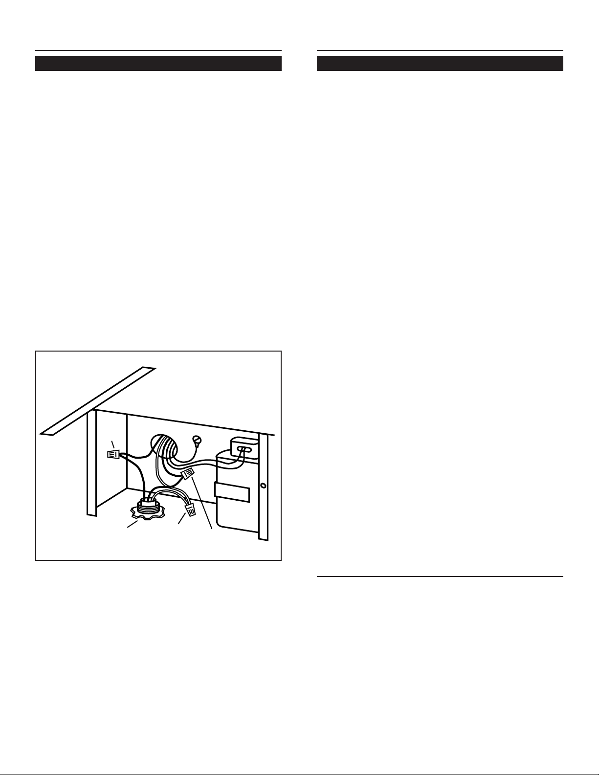
Importante: cuando use el Modelo 332H con los tiros descendentes
Eclipse de Broan Modelos 2830-A o 2836-A: Compre un juego de
control de velocidad N.º 97011927 en su distribuidora Broan para
sustituir el control de velocidad de su tiro descendente.
1. Ubique el ventilador de manera que la longitud de los conductos y el
número de codos y transiciones necesarios sean mínimos.
Por favor note: cuando use el ventilador con el tiro descendente
Eclipse de Broan: El tiro descendente tiene una descarga de 3¼ x
10" (8.3 x 25.4 cm) Hay transiciones disponibles para conectarlo
a la entrada redonda de 10" (25.4 cm) en este ventilador de montaje
exterior.
TODASLAS INSTALACIONES
MODELO VOLTIOS AMPERIOS PCM TAMAÑO DE
CONDUCTO
331H 120 2.4 600 10" (25.4 cm) DIÁM.
332H 120 5.7 900 10" (25.4 cm) DIÁM.
PARA LA PERSONA QUE REALIZA LA INSTALACIÓN: Entregue este manual al dueño de la casa
AL DUEÑO DE LA CASA: Las instrucciones de uso y cuidado se encuentran en la página 11.
MODELOS 331H Y 332H
VENTILADOR DE MONTAJE EXTERIOR
ESPECIFICACIONES
PLANIFIQUE LA INSTALACIÓN
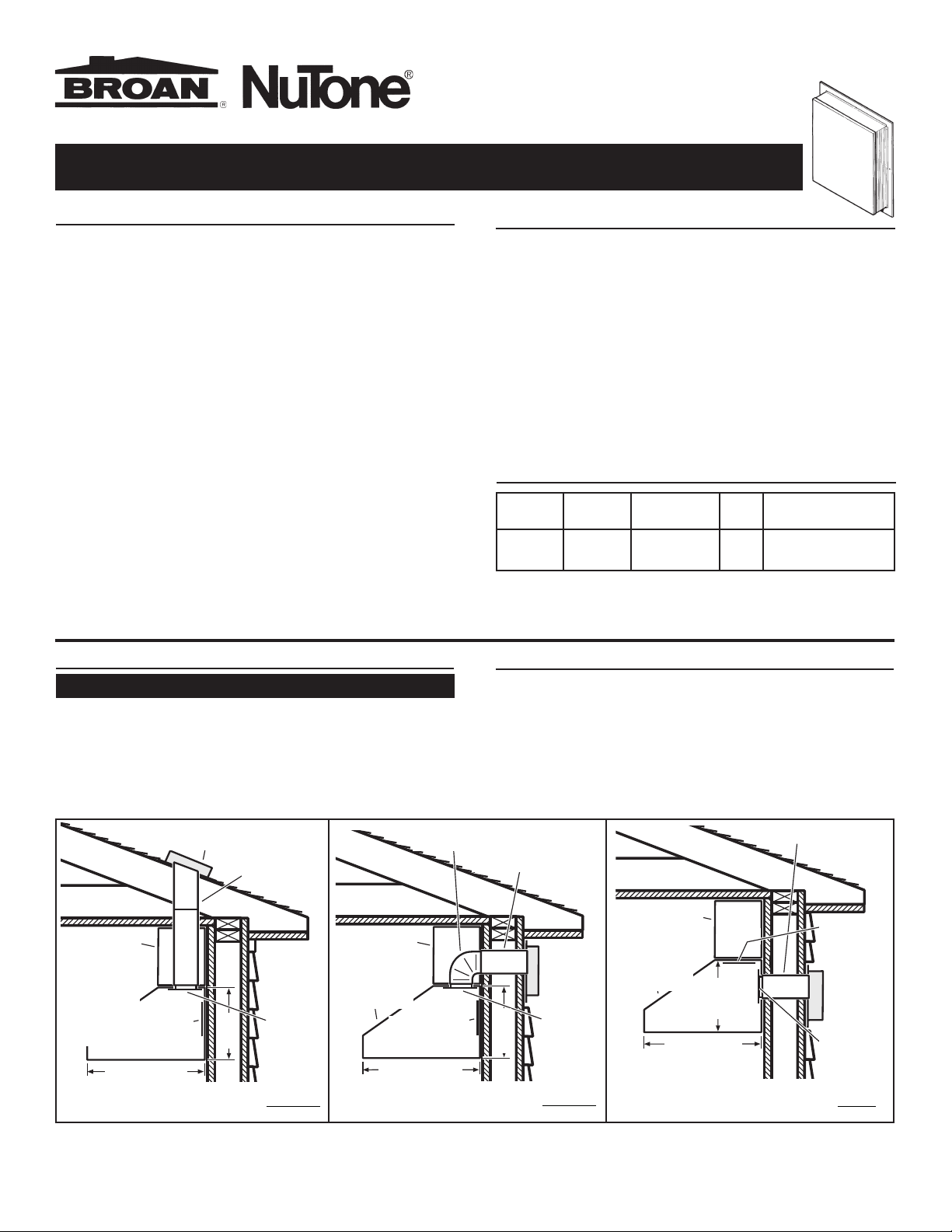
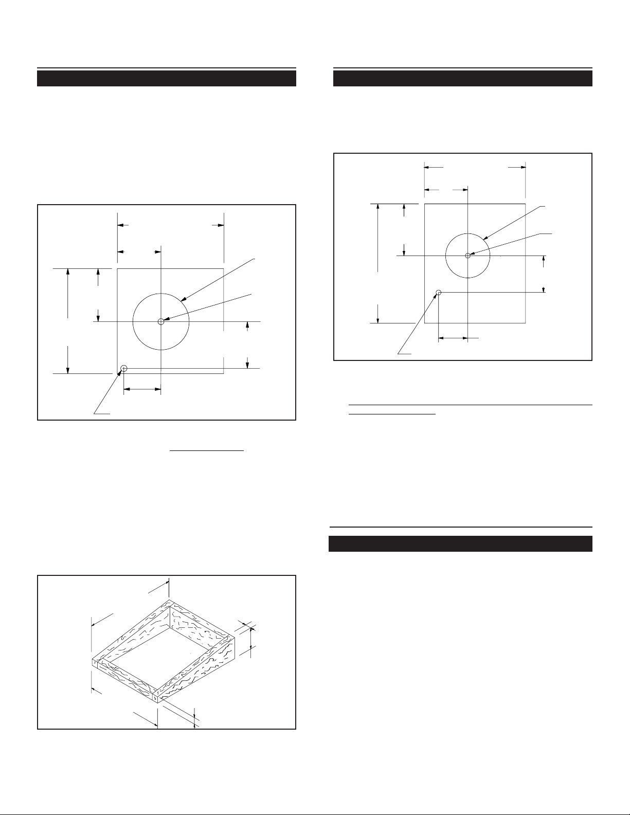
INSTALACIÓNTÍPICADEMONTAJEEN EL TECHO
(descarga vertical)
INSTALACIÓNTÍPICADEMONTAJE EN LA PARED
(descarga vertical, codo a horizontal) INSTALACIÓNTÍPICA DE MONTAJEENLA PARED
descargahorizontal)
2. Cuando sea posible, el ventilador se debe centrar entre los montantes
de la pared o entre las vigas del techo.
3. Evite la tubería, cables u otros conductos que puedan estar tendidos
por la pared.
4. Asegúrese de que haya suficiente espacio para cualquier transición
que pueda necesitarse entre el ventilador y los conductos de conexión.
5. Para obtener el mejor rendimiento, coloque las transiciones lo más
cerca posible del ventilador (esto es, el tiro descendente)
NOTA: La descarga horizontal requiere la reubicación de la placa
de cubierta de la abertura del conducto. Consulte las instrucciones
en el manual de la campana.
PLANIFIQUE LA INSTALACIÓN
VENTILADOREXTERIOR
MODELO 331H o 332H
CONDUCTO
REDONDODE
10" (25.4 CM)
PLAFÓN
CUBIERTADE
LACAMPANA
DE PARED (hay
disponible una
cubierta tipo
isla)
PLACADE
CUBIERTA DE LA
ABERTURADEL
CONDUCTO
PLACA
SIN
ACABAR
24" (60.9 cm) ó
27" (68.6 cm)
18"
(45.7
cm)
PLAFÓN
PLAFÓN
PLACADE
CUBIERTA DE LA
ABERTURADEL
CONDUCTO
PLACA
SIN
ACABAR
CUBIERTA DE LA
CAMPANADE
PARED(hay
disponible una
cubierta tipo isla)PLACADE
CUBIERTA DE LA
ABERTURADEL
CONDUCTO
PLACA
SIN
ACABAR
VENTILADOR
EXTERIOR
MODELO331H
o 332H
CONDUCTO
REDONDODE10"
(25.4 CM)
CUBIERTA DE LA
CAMPANADE
PARED(hay
disponible una
cubierta tipo isla)
24" (60.9 cm) ó
27" (68.6 cm)
24" (60.9 cm) ó
27" (68.6 cm)
VENTILADOR
EXTERIOR
MODELO331H
o 332H
PLACADE
CUBIERTADELA
ABERTURADEL
CONDUCTO
CONDUCTOREDONDO
DE 10" (25.4 CM)
18"
(45.7
cm)
18"
(45.7
cm)
CODOREDONDO
10" (25.4 CM)
Página 9

Page Lm
1. Seleccione unlugaren laparedexterior. Asegúrese dequeno haya
montantes de la pared, tubería ni cables tendidos en el área de la
abertura.
2. Haga un orificio guía en el centro del área de la abertura.
3. Marque unrectángulo de 25x 29-1/2" (63.5x 74.9 cm)en la pared
ubicado desde el orificio guía como se muestra en la Figura 3.
4. Haga un orificio rectangular sólo en el forrado. No corte el
revestimiento exterior. Clave todos los extremos del forrado.
5. Marque un círculo de 11" (27.9 cm) de diámetro centrado en el
agujero guía y marque el centro del orificio de 1-1/4" (3.2 cm) de
diámetro para el cableado eléctrico.
6. Haga elorificio de11" (27.9cm) enel revestimientoexterior yhaga
un orificio de 1-1/4" (3.2 cm) como está marcado.
PREPARE EL VENTILADOR
1. Desempaque elconjunto del ventilador
2. Quite la cubierta y los tornillos.
3. Quite y deseche el cartón de la rueda del ventilador.
4. Quite la cubierta de la caja de conexiones y los tornillos.
5. Coloque un conectador de cables apropiado, aprobado por U.L.,
en el orificio que se encuentra en la parte posterior de la caja de
conexiones.
PREPARE EL LUGAR DE LA
INSTALACIÓN
25"
Figura 3
INSTALACIONES EN EL TECHO
9-1/8"
25"
29-1/2"
2"
PREPARE EL LUGAR DE LA
INSTALACIÓN
INSTALACIONES EN LA PARED
TODASLAS INSTALACIONES
1. Ubique elventilador enla pendiente posteriordel techo.Colóquelo
enun área en lacual minimice lalongitud del tramode conductos.
Esta área debe estar libre de obstáculos (cables de T.V., cables
eléctricos, etc.). Recuerde que si la parte superior del ventilador
está al ras del pico del techo, no se verá desde la calle. Mantenga
en mente esta ubicación aproximada mientras trabaja desde el
ático.
2. Marque un punto a media distancia entre las vigas del techo.
3. Haga un orificio guía a través del techo en este punto.
4. Desde el exterior, use este orificio guía como el punto de inicio y
marque el corte rectangular, y -quite sólo las tejas de esta área.
Consulte la Figura 1.
5. Marque un círculo de 11" (27.9 cm) de diámetro centrado en el
agujero guía y marque el centro del orificio de 1-1/4" (3.2 cm) de
diámetro para el cableado eléctrico. Consulte la Figura 1.
6. Corte la tabla o tablas del techo a lo largo del círculo de 11" (27.9
cm) de diámetro y haga un orificio de 1-1/4" (3.2 cm) como está
marcado.
7. Para instalar un ventilador sobre un techo plano, construya un
bastidor para soportar el ventilador, con una pendiente mínima
de 2/12. El extremo de descarga del ventilador debe apuntar
en dirección contraria a los vientos dominantes.
Figura 1 20¾”(52.7cm)
8½”
(21.6
cm)
10-3/8"
(26.4 cm)
20½”
(52.1 cm)
Orificio de
11" (27.9 cm)
de diámetro
Orificio
guía
9-1/8"
(23.2 cm)
7¼” (18.4 cm)
Orificio de 1¼” (3.2 cm) de diámetro
Figura 2 29½”
(74.9 cm)
25"
(63.5 cm) 2"(5.08
cm)
2"(5.08
cm)
7"
(17.8 cm)
Orificio de 1¼” (3.2 cm) de diámetro
7¼” (18.4 cm)
Orificio
guía
orificio de 11"
(27.9 cm) de
diámetro
25" (63.5 cm)
9-1/8"
(23.2 cm)
10¾”
(27.3 cm)
1
2-7/8"
(32.7 cm)
29½”
(74.9 cm)
Página10

Page Lm
1. Quitelos clavos del techode las 2/3 partesde las tejas superiores
queseencuentranalrededor deláreadecorte ylevantelastejas con
cuidadoparapermitirque lahojacubrejuntasposterior delacubierta
delventilador se ajuste debajode ellas.
2. Centre el anillo del ventilador en el orificio de 11" (27.9 cm),
asegurándosede queel orificiodel cableadoeléctrico, de 1¼” (3.2
cm) de diámetro, quede alineado con el orificio de la caja de
conexiones.
3. Monte el ventilador en el techo con los seis tornillos que se
proporcionan. Losseis orificios del panel posteriordeben quedar
cubiertos,de otramanerala humedadquepenetreenla cubiertase
puede filtrar al interior de la casa.
4. Utilizandoun cementopara techode buenacalidad, selletodas las
tejas alrededor de la cubierta y de la hoja cubrejuntas, así como
alrededor de la cabeza de los tornillos de montaje.
5. Pase los cables eléctricos a través del orificio de la caja de
conexiones y asegúrelos de acuerdo con los códigos locales.
6. Haga lasconexiones eléctricas utilizandoel conectador adecuado
parael tipode cables que está usando.Conecte blancocon blanco,
negrocon negro y verdecon verde o conel hilo desnudo. Consulte
la Figura 4.
7. Vuelva acolocar la cubiertade la cajade conexiones ylos tornillos.
Nopermita que loscables quedenatrapados debajo dela cubierta.
8. Verifique el movimiento libre del regulador de tiro antes de instalar
la cubierta y los tornillos.
9. Suministre energía y revise la operación del ventilador.
120 VAC
LINE IN
BLACK
TO
BLACK
WHITE
TO
WHITE
GREEN
TO
GREEN
1. Coloque un reborde grande de material de calafateo en el lado
posterior de la cubierta, a lo largo del borde externo.
2. Centre el anillo del ventilador en el orificio de 11" (27.9 cm),
asegurándosede queel orificiodel cableadoeléctrico, de1 ¼”(3.2
cm) de diámetro, quede alineado con el orificio de la caja de
conexiones.
3. Monte el ventilador en la pared con los seis tornillos que se
proporcionan. Los seis orificios del panel posterior deben quedar
cubiertos, de otra manera la humedad que penetre en la cubierta
se puede filtrar al interior de la casa.
4. Utilizando materialde calafateode buena calidad,selle alrededor
de la cabeza de los tornillos de montaje.
5. Pase los cables eléctricos a través del orificio de la caja de
conexiones y asegúrelos de acuerdo con los códigos locales.
6. Haga lasconexiones eléctricasutilizandoel conectadoradecuado
parael tipode cable queestá usando.Conecte blancocon blanco,
negrocon negroy verdecon verde ocon elhilo desnudo.Consulte
la Figura 4.
7. Vuelva acolocar lacubierta dela cajade conexiones ylos tornillos.
Nopermita queloscables quedenatrapados debajode lacubierta.
8. Verifique elmovimiento libredel regulador detiro antesde instalar
la cubierta y los tornillos.
9. Suministre energía y revise la operación del ventilador.
10. Las aletas superior y laterales de la placa posterior se pueden
cubrir con tiras de adorno. No obstruya con la tira de adorno la
aberturade larejilla quese encuentraen laparte inferior.Si lohace
afectaráadversamente el funcionamiento del ventilador.
USO Y CUIDADO
Desconecteel suministroeléctrico ybloquee elpanel deservicio antes
de limpiar o dar servicio a esta unidad.
LIMPIEZA
Quitela cubierta y cuidadosamenteaspire el ventilador yel interior de
lacubierta.Tengacuidado denodoblarla ruedadelventiladorni dañarla
de alguna otra manera.
LUBRICACIÓN DEL MOTOR
Elmotor estápermanentemente lubricado. Nolubrique nidesmonte el
motor.
Figura 4
INSTALE EL VENTILADOR
INSTALACIONES EN EL TECHO
INSTALE EL VENTILADOR
INSTALACIONES EN LA PARED
NEGRO
A
NEGRO
LÍNEA DE
ENTRADA
DE 120 V
BLANCO
ABLANCO VERDE
A VERDE
Página11

Page Lm
CLAVE
N.º PIEZA Nº. DESCRIPCIÓN
1 97011795 Conjunto de la caja de ventilación
2 98008507 Regulador de tiro
3 93260454 Tuerca para metales, #18-18 tipo U (7 req.)*
4 99100484 Aislador (3 req.)
5 99260477 Tuerca Whiz, 1/4" - 20 (3 req.)*
6 98008511 Rejilla
7 99100379 Regulador de tiro Heyco (2 req.)
8 99080396 Motor con capacitor (Modelo 332H)
99080397 Motor con capacitor (Modelo 331H)
10 98008509 Cubierta de la caja de conexiones
11 98008588 Pinza del capacitor
12 98008510 Cubierta de la caja de ventilación
13 99020263 Ruedadel ventilador (Modelo332H)
99020264 Ruedadel ventilador (Modelo 331H)
14 99140145 Resorte del regulador de tiro
15 99400055 Heyco
16 99100517 Sello de espuma (4 req.)
17 99150471 Tornillo hexagonal, #10 - 32 x 1/2"*
18 99150535 Tornillo hexagonal, #8-16 x 3/8 (2 Req.)*
19 99271110 Capacitor 15 MFD
*Herraje estándar, se puede comprar en cualquier tienda local.
Pida siempre piezas de repuesto haciendo referencia al número de
parte, no al número de clave.
16
13
2
6
1
12
10
5
4
4
8
5
17
15
18 14
18 19
PIEZAS DE REPUESTO
MODELOS 331H Y 332H
3
7
11
99043017B
GARANTIA BROAN LIMITADA POR UN AÑO
Broan garantiza al consumidor comprador original de sus productos
que dichos productos carecerán de defectos en materiales o en
mano de obra por un período de un año a partir de la fecha original
de compra. NO EXISTEN OTRAS GARANTIAS, EXPLICITAS O
IMPLICITAS, INCLUYENDO, PERO NO LIMITADAS A, GARANTIAS
IMPLICITAS DE COMERCIALIZACION O APTITUD PARA UN
PROPOSITO PARTICULAR.
Durante el período de un año, y a su propio criterio, Broan reparará
o reemplazará, sin costo alguno cualquier producto o pieza que se
encuentre defectuosa bajo condiciones normales de servicio y uso.
ESTA GARANTIA NO SE APLICA A TUBOS Y ARRANCADORES DE
LAMPARAS
FLUORESCENTES. Esta garantía no cubre (a) mantenimiento y
servicio normales o (b) cualquier producto o piezas que hayan sido
utilizadas de forma errónea, negligente, que hayan causado un
accidente, o que hayan sido reparadas o mantenidas
inapropiadamente (por otras compañías que no sean Broan),
instalación defectuosa, o instalación contraria a las instrucciones de
instalación recomendadas.
La duración de cualquier garantía implícita se limita a un período de
un año como se especifica en la garantía expresa. Algunos estados
no permiten limitaciones en cuanto al tiempo de expiración de una
garantía implícita, por lo que la limitación antes mencionada puede
no aplicarse a usted.
LA OBLIGACION DE BROAN DE REPARAR O REEMPLAZAR,
SIGUIENDO EL CRITERIO DE BROAN, DEBERA SER EL UNICO Y
EXCLUSIVO RECURSO LEGAL DEL COMPRADOR BAJO ESTA
GARANTIA. BROAN NO SERA RESPONSABLE POR DAÑOS
INCIDENTALES, CONSIGUIENTES, O POR DAÑOS ESPECIALES
QUE SURJAN A RAIZ DEL USO O DESEMPEÑO DEL PRODUCTO.
Algunos estados no permiten la exclusión o limitación de daños
incidentales o consiguientes, por lo que la limitación antes
mencionada puede no aplicarse a usted.
Esta garantía le proporciona derechos legales específicos, y usted
puede también tener otros derechos, los cuales varían de estado a
estado. Esta garantía reemplaza todas las garantías anteriores.
Para calificar en la garantía de servicio, usted debe (a) notificar a
Broan al domicilio o el número de teléfono abjajo, (b) dar el número
del modelo y la identificación de la pieza, y (c) describir la naturaleza
de cualquier defecto en el producto o pieza. En el momento de
solicitar servicio cubierto por la garantía, usted debe de presentar
evidencia de la fecha original de compra.
Broan-NuTone LLC, 926 West State Street, Hartford, WI
53027 (1-800-637-1453)
NuTone, Inc., 4820 Red Bank Road, Cincinnati, OH 45227 (1-
800-543-8687)
Broan-NuTone Canada, Inc., 1140 Tristar Drive,
Mississauga, Ontario L5T 1H9 (1-888-882-7626)
Página12
Other manuals for NuTone 331H
3
This manual suits for next models
3
Table of contents
Languages:
Other Broan Blower manuals

Broan
Broan P12 User manual

Broan
Broan Best ILB11 User manual

Broan
Broan P12D User manual

Broan
Broan NuTone 331H User manual

Broan
Broan NuTone 336 User manual

Broan
Broan HLB3 User manual

Broan
Broan Best EB15 User manual

Broan
Broan HLB9 User manual

Broan
Broan Exterior Blower 335 User manual

Broan
Broan RM325H User manual