manuals.online logo
Brands
  1. Home
  2. •
  3. Brands
  4. •
  5. Broan
  6. •
  7. Fan
  8. •
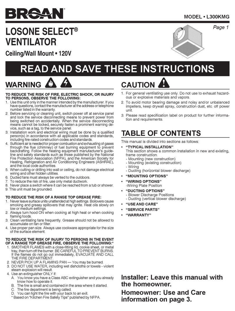
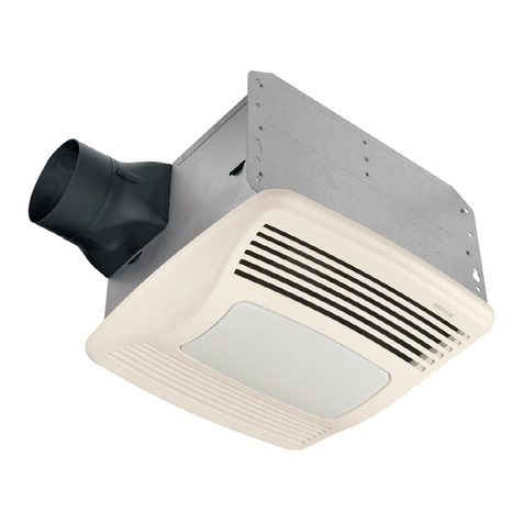
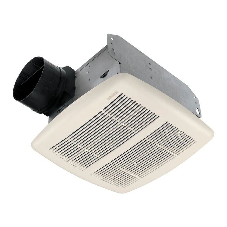
  9. Broan QT130E User manual

Broan QT130E User manual

Other manuals for QT130E

1

Other Broan Fan manuals

Broan SMD6 User manual

Broan

Broan SMD6 User manual

Broan ZB110 User manual

Broan

Broan ZB110 User manual

Broan DX90 User manual

Broan

Broan DX90 User manual

Broan ULTRA Pro RB80L User manual

Broan

Broan ULTRA Pro RB80L User manual

Broan QTXE150FLT User manual

Broan

Broan QTXE150FLT User manual

Broan XB 110 User manual

Broan

Broan XB 110 User manual

Broan XB110HL User manual

Broan

Broan XB110HL User manual

Broan SMSK102 User manual

Broan

Broan SMSK102 User manual

Broan QTR050F User manual

Broan

Broan QTR050F User manual

Broan NuTone QTRE080H User manual

Broan

Broan NuTone QTRE080H User manual

Broan ChromaComfort User manual

Broan

Broan ChromaComfort User manual

Broan 512 User manual

Broan

Broan 512 User manual

Broan 696 User manual

Broan

Broan 696 User manual

Broan LOSONE SELECT L400L User manual

Broan

Broan LOSONE SELECT L400L User manual

Broan QT140LE User manual

Broan

Broan QT140LE User manual

Broan ULTRA SILENT QTXE150 User manual

Broan

Broan ULTRA SILENT QTXE150 User manual

Broan 502 User manual

Broan

Broan 502 User manual

Broan ULTRA Pro RB110L1 User manual

Broan

Broan ULTRA Pro RB110L1 User manual

Broan QT DC Series User manual

Broan

Broan QT DC Series User manual

Broan XB50L User manual

Broan

Broan XB50L User manual

Broan 744C User manual

Broan

Broan 744C User manual

Broan QT140E User manual

Broan

Broan QT140E User manual

Broan 741BR User manual

Broan

Broan 741BR User manual

Broan NuTone ROOMSIDE Series Installation guide

Broan

Broan NuTone ROOMSIDE Series Installation guide

Popular Fan manuals by other brands

Minka Group minkaAire Wave F843 instruction manual

Minka Group

Minka Group minkaAire Wave F843 instruction manual

Airflow Adroit DV50 instruction manual

Airflow

Airflow Adroit DV50 instruction manual

Vornado 270 Series owner's guide

Vornado

Vornado 270 Series owner's guide

comfort air TH-10D instruction manual

comfort air

comfort air TH-10D instruction manual

Livoo DOM386 instruction manual

Livoo

Livoo DOM386 instruction manual

Holmes BLIZZARD HAOF-90 owner's guide

Holmes

Holmes BLIZZARD HAOF-90 owner's guide

Taurus GRECO 16 ELEGANCE manual

Taurus

Taurus GRECO 16 ELEGANCE manual

Quorum PINNACLE installation instructions

Quorum

Quorum PINNACLE installation instructions

Monte Carlo Fan Company 3DIR58RBD-V1 Owner's guide and installation manual

Monte Carlo Fan Company

Monte Carlo Fan Company 3DIR58RBD-V1 Owner's guide and installation manual

Craftmade UH52 installation guide

Craftmade

Craftmade UH52 installation guide

Jocel JVA030658 instruction manual

Jocel

Jocel JVA030658 instruction manual

MIKA MFB1211/GR user manual

MIKA

MIKA MFB1211/GR user manual

Harbor Breeze RLG52NWZ5L manual

Harbor Breeze

Harbor Breeze RLG52NWZ5L manual

Allen + Roth L1405 instruction manual

Allen + Roth

Allen + Roth L1405 instruction manual

ViM KUBAIR F400 ECOWATT Technical manual

ViM

ViM KUBAIR F400 ECOWATT Technical manual

HIDRIA R10R-56LPS-ES50B-04C10 user guide

HIDRIA

HIDRIA R10R-56LPS-ES50B-04C10 user guide

BLAUBERG Ventilatoren CENTRO-M 100 L user manual

BLAUBERG Ventilatoren

BLAUBERG Ventilatoren CENTRO-M 100 L user manual

Triangle Engineering HEAT BUSTER SPL Series owner's manual

Triangle Engineering

Triangle Engineering HEAT BUSTER SPL Series owner's manual

manuals.online logo
manuals.online logoBrands
  • About & Mission
  • Contact us
  • Privacy Policy
  • Terms and Conditions

Copyright 2025 Manuals.Online. All Rights Reserved.

Page 1
MODEL QT130E
WARNING
TO REDUCE THE RISK OF FIRE, ELECTRIC SHOCK, OR IN-
JURY TO PERSONS, OBSERVE THE FOLLOWING:
1. Use this unit only in the manner intended by the manufacturer.
If you have questions, contact the manufacturer at the address
or telephone number listed in the warranty.
2. Before servicing or cleaning unit, switch power off at service
panel and lock the service disconnecting means to prevent
power from being switched on accidentally. When the service
disconnecting means cannot be locked, securely fasten a
prominent warning device, such as a tag, to the service panel.
3. Installation work and electrical wiring must be done by a
qualified person(s) in accordance with all applicable codes
and standards, including fire-rated construction codes and
standards.
4. Sufficient air is needed for proper combustion and exhausting
of gases through the flue (chimney) of fuel burning equip-
ment to prevent backdrafting. Follow the heating equipment
manufacturer’s guideline and safety standards such as those
published by the National Fire Protection Association (NFPA),
and the American Society for Heating, Refrigeration and Air
Conditioning Engineers (ASHRAE), and the local code authori-
ties.
5. When cutting or drilling into wall or ceiling, do not damage
electrical wiring and other hidden utilities.
6. Ducted fans must always be vented to the outdoors.
7. Acceptable for use over a tub or shower when connected to
a GFCI (Ground Fault Circuit Interrupter) - protected branch
circuit (ceiling installation only).
8. This unit must be grounded.
CAUTION
1. For general ventilating use only. Do not use to exhaust hazard-
ous or explosive materials and vapors.
2. This product is designed for installation in ceilings up to a
12/12 pitch (45 degree angle). Duct connector must point up.
DO NOT MOUNT THIS PRODUCT IN A WALL.
3. To avoid motor bearing damage and noisy and/or unbalanced
impellers, keep drywall spray, construction dust, etc. off power
unit.
4. Please read specification label on product for further informa-
tion and requirements.
MODEL QT130E
VENTILATION FAN
READ AND SAVE THESE INSTRUCTIONS
Installer: Leave this manual with
the homeowner.
OPERATION
Use an on/off switch or speed control to operate this ventilator.
See “Connect Wiring” for details.
CLEANING & MAINTENANCE
For quiet and efficient operation, long life, and attractive appear-
ance - lower or remove grille and vacuum interior of unit with the
dusting brush attachment.
The motor is permanently lubricated and never needs oiling. If the
motor bearings are making excessive or unusual noises, replace
the blower assembly (includes motor and impeller).
Page 2
MODEL QT130E
PLAN THE INSTALLATION
Cooking
Equipment
Floor
COOKING AREA
Do not install above or
inside this area.
45o45o
NOT FOR USE IN
A COOKING AREA.
TYPICAL
INSTALLATIONS
Housing mounted to I-joists.
Use I-joist spacer block (provided).
Housing mounted to joists.
Housing mounted to truss.
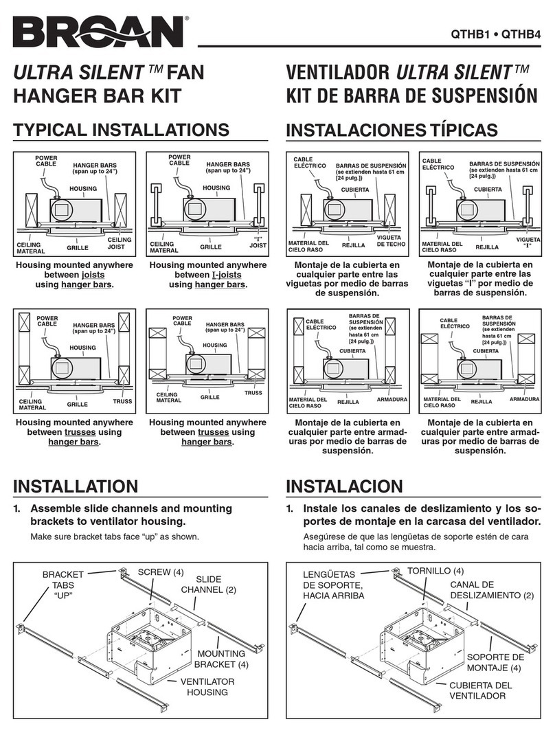
To mount housing anywhere between joists, i-joists or trusses, use
optional hanger bar kit QTHB1 (sold separately).Follow mounting
instructions included with kit.
ROOF CAP*
(with built-in
damper)
WALL CAP*
(with built-in
damper)
6-IN. or 4-IN.
ROUND
ELBOWS*
6-IN. or 4-IN. ROUND
DUCT*
FAN
HOUSING
Seal gaps
around
housing.
Seal duct
joints with
tape.
Keep duct
runs short.
INSULATION
(Place around and
over fan housing.)
POWER
CABLE*
*Purchase
separately.
OR
Page 3
MODEL QT130E
5. Connect electrical wiring.
Run 120 VAC house wiring to installation location. Use
proper UL approved connector to secure house wiring to
wiring plate. Connect wires as shown in wiring diagrams.
CONNECT WIRINGINSTALL HOUSING & DUCT
1. Bend
housing
tabs.
Use a pliers to
bend housing
TABS out to 900.
2. Mount
housing to
joist.
Hold housing
in place so that
the housing
tabs contact the
bottom of the
joist. The hous-
ing mounts with
four (4) screws
or nails. Screw or
nail housing to joist through lowest holes in each mount-
ing flange, then through highest holes. NOTE: Mounting
to I-JOIST (shown) requires use of SPACERS (included)
between the highest hole of each mounting flange and the
I-joist.
SPACER
(use for mounting to I-Joist)
I-JOIST
TABS
3. Attach
damper/duct
connector.
Snap damper /
duct connector
onto housing.
Make sure con-
nector is flush with
top of housing and
damper flap falls
closed. If using
4-inch ductwork,
install 6” to 4” duct
reducer (included) over duct connector.
4. Install
6-inch or
4-inch round
ductwork.
Connect 6-inch
or 4-inch round
ductwork to
damper / duct
connector. Run
ductwork to a roof
cap or wall cap.
Tape all ductwork
connections to make them secure and air tight.
Page 4
MODEL QT130E
SERVICE PARTS
99044827B
Key No. Part No. Description
1 97016466 Housing
2 97018562 Duct Connector - 6”
3 98010102 Wiring Plate
4 99170245 Screw, #8-18 X .375
5 97018010 Wire Panel/Harness Assembly
6 97019540 Blower Assembly
7 97017621 Grille Assembly
(includes key no. 8)
8 99140199 Grille Spring (2 req’d)
9 97018014 Spacer (2 supplied)
10 99420665 Thumbscrew, #8-18 x .375
11 475 Duct Reducer - 6” to 4”
INSTALL GRILLE
7. Attach grille
to housing.
Squeeze grille
springs and insert
them into tabs
on each side of
housing.
8. Push grille
against
ceiling.
6. Finish ceiling.
Install ceiling material. Cut out around housing.
Order service parts by “Part No.” - not by “Key No.”
SERVICE NOTE
To remove Blower
Assembly:
Unplug motor.
Remove
thumbscrew (10)
from motor plate
flange.
Find the single TAB
on the motor plate
(located next to the
receptacle).
Push up near motor
plate tab while
pushing out on side
of housing. Or insert
a straight-blade
screwdriver into slot
in housing (next to
tab) and
twist screwdriver.
Discover other home ventilations on our website.