manuals.online logo
Brands
  1. Home
  2. •
  3. Brands
  4. •
  5. Broan
  6. •
  7. Fan
  8. •
  9. Broan ULTRA-SENSAIRE HS110UE User manual

Broan ULTRA-SENSAIRE HS110UE User manual

TYPICAL INSTALLATION
INSTALLER: LEAVE THIS
MANUAL WITH THE
HOMEOWNER.
HOMEOWNER: USEAND
CAREINSTRUCTIONSON
PAGE 3.
MODEL HS110UE
ULTRA-SENSAIRE®
HUMIDITY SENSING
CEILING FAN
READ AND SAVE THESE INSTRUCTIONS
WARNING
TO REDUCE THE RISK OF FIRE, ELECTRIC SHOCK, OR
INJURY TO PERSONS, OBSERVE THE FOLLOWING:
1. Usethisunitonlyin themannerintendedby themanufacturer.
Ifyouhavequestions,contactthemanufacturerattheaddress
or telephone number listed in the warranty.
2. Before servicing or cleaning unit, switch power off at service
panel and lock the service disconnecting means to prevent
power from being switched on accidentally. When the service
disconnecting means cannot be locked, securely fasten a
prominent warning device, such as a tag, to the service panel.
3. Installation work and electrical wiring must be done by a
qualified person(s) in accordance with all applicable codes
and standards, including fire-rated construction codes and
standards.
4. Sufficient air is needed for proper combustion and exhausting
of gases through the flue (chimney) of fuel burning equipment
to prevent backdrafting. Follow the heating equipment
manufacturer’s guideline and safety standards such as those
publishedby the NationalFire ProtectionAssociation (NFPA),
and the American Society for Heating, Refrigeration and Air
Conditioning Engineers (ASHRAE), and the local code au-
thorities.
5. When cutting or drilling into wall or ceiling, do not damage
electrical wiring and other hidden utilities.
WARNING
6. Ducted fans must always be vented to the outdoors.
7. If this unit is to be installed over a tub or shower, it must be
marked as appropriate for the application and be connected
toaGFCI(GroundFaultCircuit Interrupter) -protectedbranch
circuit.
8. Never place a switch where it can be reached from a tub or
shower.
9. This unit must be grounded.
CAUTION
!
1. For general ventilating use only. Do not use to exhaust
hazardous or explosive materials and vapors.
2. This product is designed for ceiling installation only.DO NOT
MOUNT THIS PRODUCT IN A WALL.
3. To avoid humidity sensor damage, motor bearing damage
and noisy and/or unbalanced impellers, keep drywall spray,
construction dust, etc. off power unit.
4. Please read specification label on product for further informa-
tion and requirements.
HOUSING
MOUNTING
BRACKET
CEILING
JOIST
POWER
CABLE
GRILLE FINISHED CEILING
4" ROUND
DAMPER/DUCT
CONNECTOR
This unit can be installed anywhere between joists
using mounting brackets provided.
PLAN THE INSTALLATION
The location of your
ULTRA-SENSAIRE®fan is
very important. Follow
these guidelines for best
operation:
• TheULTRA-SENSAIRE®
fan uses a humidity
sensor that responds to
bothincreasesinhumidity
and to humidity levels.
Thehumiditysensor may
turn the fan ON when
environmental
conditions change. If the
fan continuously
responds to changing environmental conditions, "SENSITIVITY"
adjustment may be required.
• Locate unit above (GFCI protected circuit required) or within 5 feet of
shower head.
• Locate unit away from heating or cooling sources which can affect
humidity levels.
• Do not locate near window. Unit may respond to the outdoor humidity
level.
• Unit must be installed in ceiling to properly sense moisture.
• Locate unit only on flat ceilings up to 12 feet high for proper sensing.
• The fan will operate most efficiently when located where the shortest
possible duct run and minimum number of elbows will be needed.
POWER
CABLE
SUSPENDED CEILING
MATERIAL
4" ROUND DUCT
HOUSING
1
::
bathroomsource
.com
Call 1-800-667-8721 anywhere in the US and Canada -
www.bathroomsource.com
PREPARE THE FAN / LIGHT
2
FLUSH
NOTE: Theduct connector has a counter-balanceddamper flap.
Theflapwillbe"open"approx.1"whenductconnectorisattached
to housing. This design permits insulation to be in direct contact
with fan/light housing per UL (Underwriters Laboratories) stan-
dards. The slightest backdraft, however, will close the damper
flap, preventing air from entering unit or finished space.
1½" FOR
½" DRYWALL
INSTALL THE FAN / LIGHT
(CONT'D)
INSTALL THE FAN / LIGHT
1. Remove the screw holding
theblower assemblyinplace.
Lift assembly from housing.
2. Slide adjustable mounting
brackets into bracket chan-
nelsonhousing.NOTE: Hous-
ing may be mounted directly
to joist using keyholes pro-
vided.
WIRE THE FAN
1. Thethree most common methodsofwiringthisfanareshown.
Follow the one you chose when you planned the installation.
NOTE: Anextradeep-gangedand/ordouble-gangedboxis
usually required. Check code requirements.
2. Remove wiring cover. Run electrical cable as directly as
possible to unit. Make wiring connections. Do not allow cable
to touch sides or top of unit after installation is complete. Push
all wiring into corner of unit. Replace wiring cover.
3. Replace fan assembly and secure with captive screw.
4. Plug wiring connectors into their receptacles.
SENSOR
FAN
BLACK
BLACK
RED
WHITE
GROUND
120 VAC
LINE IN
UNIT
BLACK
WHITE
SWITCH BOX
ON (AUTO)
OFF (MANUAL)
ON/OFF SWITCH
GROUND
WIRING OPTION #1
Allows fan to operate in automatic mode or manual on with
timed off mode (for odor control) by cycling ON/OFF switch.
Allows fan circuit to be turned OFF when desired.
3. Hanghousing from
nails. Use measur-
ing guides on cor-
ners of housing to
check if unit will be
flush with finished
ceiling. Pound
nailstight.Forwide
joistcenters:A#8x
3/8 self-tapping
screw can be used
to join extended
brackets together
andcreate a rigid mount. To ensure a noise-free mount, crimp
the bracket channels tightly around mounting brackets.
4. Snapthedamper/ductconnectorontohousing.Makesurethat
tabsontheconnectorlockintoslotsinhousing.Topofdamper/
duct connector should be flush with top of housing.
5. Connect 4” round duct to damper/duct connector and extend
duct to outside through a roof or wall cap. Check damper to
make sure that it opens freely. Tape all duct connections to
make them secure and air tight.
➔
➔
1. Position housing between joists and extend mounting brack-
ets.Positionbracketssuchthatbottomedgeofhousingwillbe
flush with finished ceiling. Mark the top of keyhole on all four
mounting brackets.
2. Remove housing temporarily, and pound nails partially into
joists at all four marked locations.
SWITCH BOX
GROUNDED
WIRE/CLIPDETAIL
UNIT
WHITE
RED
120VACLINEIN
ON/OFF
SWITCH
BLACK
GROUND
SENSOR
FAN
UNIT
GROUND
WHITE
BLACK
BLACK
RED
BLACK
ON/OFF SWITCH
RED
WHITE
WHITE
GROUND
WIRING OPTION #2
Allows fan to operate in automatic mode or to be turned ON
independent of humidity sensing control. WIRING COVER
BLACK
SWITCH BOX
120VAC
LINE IN
OFF (AUTO)
ON (MANUAL)
ON
(MANUAL)
OFF (AUTO)
WIRE THE FAN (CONT'D)
SENSOR
FAN
BLACK
RED
120 VAC
LINE IN
UNIT
BLACK
WHITE
GROUND
WIRING OPTION #3
Fan circuit will always be in automatic mode.
ATTACH THE GRILLE
1. Squeeze grille springs
together and insert
springs into slots in
blower assembly.
2. Push grille up against
ceiling.
3. Turnonpowerandcheck
fan operation.
SENSOR OPERATION
The ULTRA-SENSAIRE® fan uses a sophisticated humidity sen-
sor that responds to: (a) rapid to moderate (user-adjustable)
increases in humidity or (b) humidity above a user-adjustable
set-point (50%-100% Relative Humidity). The humidity sensor
may occasionally turn the fan ON when environmental condi-
tions change. If the fan continuously responds to changing
environmental conditions, "SENSITIVITY" adjustment may be
required.
MANUAL ON WITH TIMED OFF
The ULTRA-SENSAIRE®fan has an additional operation fea-
ture. For odor or vapor control, the fan can be energized by
cycling the power switch. Once the fan has been energized in
this manner, it will remain on for the user-adjustable "TIMER"
period (approx. 5 to 60 minutes). This period is factory-set for
approximately 20 minutes.
To manually energize the fan:
1. If fan power switch is already ON, proceed to Step 2; other-
wise, turn power switch ON for more than 1 second.
2. Turn fan power switch OFF for less than 1 second.
3. Turn fan power switch back ON and fan will turn ON.
USE AND CARE
SENSITIVITY ADJUSTMENT
The "SENSITIVITY" has been factory set for most shower appli-
cations. However, if the fan is in a tub area or is being used for
dampnesscontrol, the"SENSITIVITY" may need to beincreased
toward maximum ("MAX."). If the control is responding too of-
ten to changing environmental conditions, movement toward
less ("MIN.") "SENSITIVITY" may be required.
To adjust the "SENSITIVITY":
1. Disconnect power at service entrance.
2. Through the grille, locate the screwdriver slot marked "SEN-
SITIVITY".
3. Using a small, flat-blade screwdriver, carefully rotate the
"SENSITIVITY" adjustment toward "MAX." or "MIN."
4. Turnon power and check operation by turning on the shower
or other humidity source until the fan turns on.
5. Repeat above steps if necessary.
TIMER ADJUSTMENT
The ULTRA-SENSAIRE®fan has a "TIMER" that can be ad-
justed from 5 to 60 minutes (factory-set at approx. 20 minutes).
This "TIMER" controls the length of time that the fan remains
ON (a) after the sensor has stopped sensing a rise in humidity
and the humidity level is below the user-adjustable set-point or
(b) after being energized by cycling the power switch.
To adjust the "TIMER":
1. Disconnect power at service entrance.
2. Through the grille, locate the screwdriver slot marked
"TIMER".
3. Using a small, flat-blade screwdriver, carefully rotate the
"TIMER" adjustment to desired setting (from 5 to 60 min-
utes).
4. Check operation by cycling the power switch as instructed
under "MANUAL ON WITH TIMED OFF" or by turning on a
humidity source until the fan turns on.
5. Turn humidity source off and time the unit.
6. Repeat above steps if necessary.
WARNING
BEFORE CLEANING, SERVICING OR ADJUSTING THE
UNIT, SWITCH POWER OFF AT SERVICE PANEL. LOCK
SERVICE PANEL TO PREVENT POWER FROM BEING
SWITCHED ON ACCIDENTALLY.
3
BROAN-NUTONE ONE YEAR LIMITED WARRANTY
Broan-NuTone warrants to the original consumer purchaser of its products that such products will be free from defects in materials or workman-
ship for a period of one year from the date of original purchase. THERE ARE NO OTHER WARRANTIES, EXPRESS OR IMPLIED, INCLUDING,
BUT NOT LIMITED TO, IMPLIED WARRANTIES OF MERCHANTABILITY OR FITNESS FOR A PARTICULAR PURPOSE.
During this one-year period, Broan-NuTone will, at its option, repair or replace, without charge, any product or part which is found to be defective
under normal use and service.
THIS WARRANTY DOES NOT EXTEND TO FLUORESCENT LAMP STARTERS AND TUBES. This warranty does not cover (a) normal
maintenance and service or (b) any products or parts which have been subject to misuse, negligence, accident, improper maintenance or repair
(other than by Broan-NuTone), faulty installation or installation contrary to recommended installation instructions.
The duration of an implied warranty is limited to the one-year period as specified for the express warranty. Some states do not allow limitation on
how long an implied warranty lasts, so the above limitation may not apply to you.
BROAN-NUTONE’S OBLIGATION TO REPAIR OR REPLACE, AT BROAN-NUTONE’S OPTION, SHALL BE THE PURCHASER’S SOLE AND
EXCLUSIVE REMEDY UNDER THIS WARRANTY. BROAN-NUTONE SHALL NOT BE LIABLE FOR INCIDENTAL, CONSEQUENTIAL OR
SPECIAL DAMAGES ARISING OUT OF OR IN CONNECTION WITH PRODUCT USE OR PERFORMANCE. Some states do not allow the
exclusion or limitation of incidental or consequential damages, so the above limitation may not apply to you.
This warranty gives you specific legal rights, and you may also have other rights, which vary from state to state. This warranty supersedes all prior
warranties.
To qualify for warranty service, you must (a) notify Broan-NuTone at the address stated below or telephone: 1-800-637-1453, (b) give the model
number and part identification and (c) describe the nature of any defect in the product or part. At the time of requesting warranty service, you must
present evidence of the original purchase date.
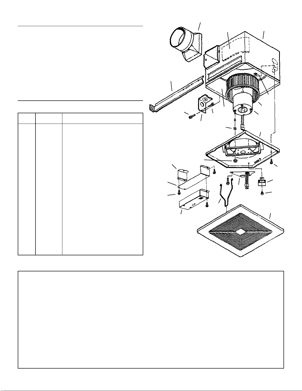
KEY PART
NO. NO. DESCRIPTION
1 97013349 Damper/Duct Connector Assembly
2 97013400 Housing Assembly
3 99500389 Insulation — Short
4 98003036 Mounting Bracket (4 Req.)
5 99500388 Insulation — Long
6 93260454 Sheet Metal Nut #8-18*
7 99020269 Impeller
8 99080455 Motor
9 97011965 Humidity Control Assembly
10 99170245 Screw #8-18 x .375 (4 Req.)*
11 98008868 Knockout Panel
12 99150471 Ground Screw #10-32 x .500*
13 99260567 Motor Nut #8-32 (4 Req.)
14 99100483 Grommet (4 Req.)
15 97016373 Wire Box Cover Assembly
16 97013401 Venturi Plate Assembly
17 99150459 Screw #8-18 x .500*
18 99140190 Grille Spring (2 Req.)
19 97013402 Grille Assembly (Includes Key No. 18)
20 97013804 Capacitor
21 99150415 Screw #8-18 x .250*
22 98010105 Bracket, Humidity Sensor
23 98010110 "Z"Bracket
24 99150491 Screw, #8-18 x .375*
-- 97013571 Blower Assembly (Includes Key Nos.
7, 8, 13, 14, 16, 20 & 21
* Standard Hardware. May be purchased locally.
Order service parts by "PART NO." — NOT by "KEY NO."
SERVICE PARTS
MODEL HS110UE
SENSOR CLEANING
The humidity sensor is mounted behind the grille. The sensor
will operate most reliably when cleaned occasionally as fol-
lows:
1. Disconnect power at service entrance.
2. Remove the grille. Use a dry dustcloth or lightly vacuum to
clean sensor and grille. DO NOT USE ABRASIVE CLOTH,
STEEL WOOLPADS, OR SCOURING POWDERS.
3. DO NOT USE cleaning sprays, solvents, or water on or near
the sensor!
USE AND CARE (CONT'D) 1
2
3
4
5
6
7
8
9
10
11 12
13
14
15
16
17
18 19
22 20
21
23
24
499043320B
Broan at bathroom::accessories
U N L I M I T E D

Other Broan Fan manuals

Broan QTXE080C User manual

Broan

Broan QTXE080C User manual

Broan 504 User manual

Broan

Broan 504 User manual

Broan QT110LE User manual

Broan

Broan QT110LE User manual

Broan ULTRA SILENT QTHB1 User manual

Broan

Broan ULTRA SILENT QTHB1 User manual

Broan 512M User manual

Broan

Broan 512M User manual

Broan Nutone 2730 eclipse User manual

Broan

Broan Nutone 2730 eclipse User manual

Broan SOLITAIRE Series User manual

Broan

Broan SOLITAIRE Series User manual

Broan LOSONE SELECT L100 SERIES Operator's manual

Broan

Broan LOSONE SELECT L100 SERIES Operator's manual

Broan 741BR Installation instructions

Broan

Broan 741BR Installation instructions

Broan LOSONE SELECT L100 User manual

Broan

Broan LOSONE SELECT L100 User manual

Broan 744 User manual

Broan

Broan 744 User manual

Broan XB50L User manual

Broan

Broan XB50L User manual

Broan 506 User manual

Broan

Broan 506 User manual

Broan LP50100DC User manual

Broan

Broan LP50100DC User manual

Broan 100HL User manual

Broan

Broan 100HL User manual

Broan QTR070C User manual

Broan

Broan QTR070C User manual

Broan LP80 User manual

Broan

Broan LP80 User manual

Broan ERV200 ECM User manual

Broan

Broan ERV200 ECM User manual

Broan QT80E User manual

Broan

Broan QT80E User manual

Broan 741BR User manual

Broan

Broan 741BR User manual

Broan ZB80ML1 User manual

Broan

Broan ZB80ML1 User manual

Broan Ventilation Fan with Light and Heater 100HFL User manual

Broan

Broan Ventilation Fan with Light and Heater 100HFL User manual

Broan QTRE100S User manual

Broan

Broan QTRE100S User manual

Broan XB110HL User manual

Broan

Broan XB110HL User manual

Popular Fan manuals by other brands

Cellini CMF75 instruction manual

Cellini

Cellini CMF75 instruction manual

Daewoo Dcool 1607 user manual

Daewoo

Daewoo Dcool 1607 user manual

Viessmann Vitovent 300-W Installation and service instructions

Viessmann

Viessmann Vitovent 300-W Installation and service instructions

Bryant ERVBBLHA Product data

Bryant

Bryant ERVBBLHA Product data

Vents TwinFresh Comfo RA1-25 user manual

Vents

Vents TwinFresh Comfo RA1-25 user manual

Turbovex CA350 User manual and installation guide

Turbovex

Turbovex CA350 User manual and installation guide

Soleus Air FTY-30 user manual

Soleus Air

Soleus Air FTY-30 user manual

SOLIS TRIPLE FAN PLUS user manual

SOLIS

SOLIS TRIPLE FAN PLUS user manual

Morris MFS-16213 instruction manual

Morris

Morris MFS-16213 instruction manual

Sandstorm STFBW19E instruction manual

Sandstorm

Sandstorm STFBW19E instruction manual

Prominence Home 51028 owner's manual

Prominence Home

Prominence Home 51028 owner's manual

ALKOVA Koko 3B instruction manual

ALKOVA

ALKOVA Koko 3B instruction manual

Ebmpapst A2D300-AP06-14 operating instructions

Ebmpapst

Ebmpapst A2D300-AP06-14 operating instructions

Orbegozo CP 73132 instruction manual

Orbegozo

Orbegozo CP 73132 instruction manual

NuTone ARP6 installation instructions

NuTone

NuTone ARP6 installation instructions

ELPLAST Aero 100 User instructions

ELPLAST

ELPLAST Aero 100 User instructions

Bionaire BUF1410C instruction manual

Bionaire

Bionaire BUF1410C instruction manual

aldes inoVEC standard Assembly instructions

aldes

aldes inoVEC standard Assembly instructions

manuals.online logo
manuals.online logoBrands
  • About & Mission
  • Contact us
  • Privacy Policy
  • Terms and Conditions

Copyright 2025 Manuals.Online. All Rights Reserved.