Broan 192 User manual

READ AND SAVE
THESE INSTRUCTIONS
MODELS 192, 194 & 198
WALL HEATERS
MODELOS 192, 194 y 198
CALENTADORES DE PARED
LEAY CONSERVE
ESTAS INSTRUCCIONES
WARNING
1. ALL ELECTRICAL WORK MUST BE DONE IN
ACCORDANCE WITH LOCAL OR NATIONAL
ELECTRICAL CODE AS APPLICABLE. FOR
SAFETY, THIS PRODUCT MUST BE
GROUNDED. IF YOU ARE UNFAMILIAR WITH
METHODS OF INSTALLING ELECTRICAL WIR-
ING, SECURE THE SERVICES OF A QUALIFIED
ELECTRICIAN.
2. WHEN WIRING, SERVICING OR CLEANING
THIS UNIT, TURN OFF POWER AND LOCK OUT
SERVICE PANEL. FAILURE TO DO SO COULD
ALLOW OTHERS OR THERMOSTAT TO TURN
ON POWER UNEXPECTEDLY WHICH MAY
CAUSE FATAL ELECTRICAL SHOCK.
3. To avoid electrical shock:
• DO NOT install unit in a tub or shower enclo-
sure or any location where it may come in con-
tact with water.
• NEVER place a switch where it can be reached
from a tub or shower.
4. DO NOT install this unit in an area where chemi-
cals and other flammables are stored or used.
Explosion and fire may result.
CAUTION
1. This product may ONLY be installed in a wall. DO
NOT MOUNT IN ANY OTHER POSITION.
2. Install heater at least 12" from floor or any adja-
cent vertical surface.
3. DO NOT locate heater behind a door, furniture,
drapes, etc., where the air flow to the unit would
be restricted.
4. Provide heater with an appropriately-rated elec-
trical circuit to prevent tripped breakers or blown
fuses. (See chart on page 2).
5. DO NOT CONNECT HEATER TO DIMMER
SWITCH OR SPEED CONTROL.
6. To avoid motor bearing damage and noisy and/
or unbalanced impellers, keep drywall spray, con-
struction dust, etc., off power unit.
7. Please read specification label on product for fur-
ther information and requirement.
PLAN THE
INSTALLATION
This heater is intended to be used to supply supple-
mental heat from a wall location in new or existing
construction.
Choose a location where edge of heater will be at
least 12" from the floor or any adjacent vertical sur-
face.
The heater can be operated using its built-in thermo-
stat or a remote thermostat (Broan Model 86W Line-
Voltage thermostat). The Broan Model 85 Kit is avail-
able for surface-mount applications. Purchase these
accessories separately.
Plan to supply the heater with proper line voltage and
appropriate power cable.
NOTE: Power can be tapped from a nearby circuit
depending on the heater wattage required and the
amperage rating of the circuit.
Heater can be converted to half-wattage to avoid over-
loading such circuits.
INSTALLER: Leave This Manual With The Homeowner. HOMEOWNER: Use and Care Information on Page 3.
INSTALADOR: Deje este manual con el dueño de casa. DUEÑO DE CASA: Información del uso y mantenimiento en la página 3.
FIG. 1
GRILLE
REJILLA
BUILT-IN
THERMOSTAT
TERMOSTATO
INCORPORADO
HEATER
HOUSING
CAJA DEL
CALENTADOR
POWER
CABLE
CABLE DE
ENERGIA
ELECTRICA
ADVERTENCIA
1. TODO ELTRABAJO ELECTRICO DEBE REALIZARSE
DE ACUERDO CON LOS CODIGOS ELECTRICOS
LOCALESY/O NACIONALES CORRESPONDIENTES.
PARA SU SEGURIDAD,ESTE PRODUCTO DEBE SER
CONECTADO A TIERRA. SI USTED NO ESTA
FAMILIARIZADO CON LOS METODOS DE
INSTALACION DEL CABLEADO ELECTRICO,
OBTENGA LOS SERVICIOS DE UN ELECTRICISTA
COMPETENTE.
2. AL HACER EL CABLEADO, LIMPIEZA O DAR
SERVICIO A ESTA UNIDAD, CORTE LA ENERGIA Y
ASEGURE EL PANEL DE SERVICIO. SI NO HACE
ESTO, ES POSIBLE QUE OTRAS PERSONAS O EL
TERMOSTATO RESUMA LA ENERGIA EN FORMA
INESPERADA, LO QUE PUEDE CAUSAR UN GOLPE
ELECTRICO MORTAL.
3. Para evitar descarga eléctrica:
• NO instale la unidad en una bañera o recinto de
ducha.
• NUNCA coloque un interruptor en un lugar que pueda
ser alcanzado desde una bañera o ducha.
4. NO instale esta unidad en un área donde se almacenen
o usen productos químicos u otros productos
inflamables. De lo contrario, pueden producirse
explosiones e incendios.
CUIDADO
1. Este producto SOLAMENTE se puede instalar en una
pared. NO LO MONTE EN NINGUNA OTRA POSICION.
2. Instale el calentador por lo menos a 30,48 cm de
distancia del piso o de alguna superficie vertical
adyacente.
3. NO COLOQUE el calentador detrás de una puerta,
muebles, cortinas, etc., donde el flujo de aire a la unidad
se encuentre restringido.
4. Proporcione al calentador un circuito eléctrico de
capacidad apropiada, a fin de impedir la desconexión
de disyuntores o quemado de fusibles. (Véase el
diagrama en la página 2).
5. NO CONECTE EL CALENTADOR A UN VARIADOR
DE LUZ O CONTROL DE VELOCIDAD.
6. Para evitar daños al cojinete del motor e impulsores ruidosos
y/o desequilibrados, mantenga la unidad de energía alejada
de rocíos de yeso, polvo de construcción, etc.
7. Para más información y requisitos, lea la etiqueta de
especificación sobre el producto.
PLANIFICACION DE LA
INSTALACION
Este calentador ha sido diseñado para proporcionar
calefacción adicional desde el cielo raso en una
construcción nueva o una ya existente.
Escoja un lugar en que el borde del calentador se
encuentre por lo menos a 30,48 cm de cualquier superficie
vertical adyacente.
Este calentador se puede poner en funcionamiento usando
su termostato incorporado o un termostato a distancia (el
termostato de tensión de línea Broan Modelo 86W). El
conjunto Broan Modelo 85 está disponible para
aplicaciones de montaje en superficie. Adquiera estos
accesorios en forma separada.
Proporcione al calentador la tensión de línea y cable de
energía eléctrica apropiados.
NOTA: La energía se puede tomar de un circuito cercano,
lo que dependerá del vatiaje requerido del calentador y
amperaje nominal del circuito.
El calentador se puede convertir a mitad de vatiaje para
evitar sobrecargar dichos circuitos.
DRYWALL
PARED DE
YESO
THERMAL
OVERLOAD
SOBRECARGA
TERMICA

FIG. 2
THERMAL
OVERLOAD
"RESET"
BUTTON
BOTON
“RESET” DE
SOBRECARGA
TERMICA
THERMOSTAT
TERMOSTATO
FIG. 3
FIG. 4
FIG. 5
El cableado viene de fábrica para las corrientes nominales
en letras oscuras. Sección “CONVERSIONES DE
CABLEADO ORIGINAL” encontrará las instrucciones de
conversión de vatiaje.
Al instalar este calentador, siga estos pasos básicos:
• Clave la caja en las vigas.
• Conecte el cable de energía eléctrica.
• Fije el conjunto del calentador y la rejilla a la caja.
(FIG. 1)
INSTALACION
DEL CALENTADOR
1. Saque el conjunto de calentador de la caja. (FIG. 2)
Saque los cuatro (4) tornillos que se muestran y saque
el conjunto del calentador.
2. Enganche la caja en las vigas de la pared. (FIG. 3)
NOTA: Sitúe la caja a una distancia por lo menos de
30,48 cm del piso o de cualquier pared adyacente.
Use las guías de medida al costado de la caja, a fin de
colocarla a nivel con la pared terminada.
Clave la caja a las vigas a través del agujero y la ranura
en ambos lados de la caja.
NOTA:En una construcción de vigas con centro de 60,96
cm (24 pulg.), se hace necesaria una armazón entre las
vigas.
CABLEADO
DEL CALENTADOR
1. Conecte el cable de electricidad a la caja. (FIG. 4)
Conecte el cable de energía eléctrica a la caja usando
el conector adecuado. Deje 15,24 cm (6 pulg.) de cable
dentro de la caja. Fije firmemente a la caja el cable de
conexión a tierra con el sujetador, tal como se muestra.
2. Cableado del conjunto de calentador. (FIGS. 5 y 6)
Conecte los alambres del conjunto de calentador a los
alambres de cable de energía. Siga el diagrama de
cableado.
Si el calentador está cableado en forma directa, use el
termostato incorporado para el control de temperatura.
Si se desea control montado en la pared, use el
termostato de tensión de línea Broan modelo 86.
Compre los controles de pared por separado.
Al usar un control de pared separado, prenda el
termostato incorporado al calentador en su graduación
más alta. No es necesario desconectar el termostato
incorporado.
Para evitar un ajuste descendente no deseado del
termostato incorporado:
1) Ponga el termostato incorporado en su graduación
más alta.
2) Quite la perilla.
3) Fije la cubierta de seguridad a la rejilla.
CONVERSIONES
DE CABLEADO OPCIONAL
1. Conversión a mitad de vatiaje. (FIG. 7)
El calentador producirá menos calor y usará menos
electricidad si se le convierte a mitad de vatiaje.
Saque del elemento de calor el alambre negro de puente
y bote éste.
2. Instalación de termostato a distancia.
Siga las instrucciones de montaje y cableado que vienen
con los controles.
COMPLETE
LA INSTALACION
1. Instale la cubierta de la caja.
Se provee una cubierta de caja para evitar que el polvo
de la construcción, rocíos de yeso, pintura, etc., dañen
el calentador.
Doble la aleta de la cubierta y póngala dentro de la caja
del calentador.
NOTA: La cubierta se pueded colocar en su lugar antes
o después de reinstalar el conjunto del calentador.
2. Reinstale el conjunto del calentador.
Fije el conjunto del calentador a la caja con cuatro (4)
tornillos.
Mire el botón “RESET” de sobrecarga térmica. El
calentador no funcionará a menos que el botón esté
oprimido.
MODELOS
192
194
198
VOLTIOS
240
240
240
AMPS
8.33/4.17
12.5/6.25
16.67/8.33
VATIOS
2000/1000
3000/1500
4000/2000
BTU/HR
6827/3413
10240/5120
13653/6827
HEATER
ASSEMBLY
MOUNTING
SCREWS
TORNILLOS DE
MONTAJE DEL
CONJUNTO
DEL
CALENTADOR
NAIL HERE-
BOTH SIDES
CLAVE AQUI
- EN AMBOS
LADOS MEASURING
GUIDES
GUIAS DE
MEDIDA
GROUNDING CLIP
DETAIL
DETALLE DEL
SUJETADOR (CLIP)
DE CONEXIÓN A
TIERRA
VOLTS
240
240
240
AMPS
8.33/4.17
12.5/6.25
16.67/8.33
WATTS
2000/1000
3000/1500
4000/2000
BTU/HR
6827/3413
10240/5120
13653/6827
BOLD ratings are factory wired. See "OPTIONAL WIR-
ING CONVERSIONS" section for wattage conversion
instructions.
Follow these basic steps when installing this heater.
• Nail housing to studs.
• Connect power cable.
• Fasten heater assembly and grille to housing.
(FIG.1)
INSTALL THE HEATER
1. Remove heater assembly from housing.
(FIG. 2)
Take out the four (4) screws shown and set heater
assembly aside.
2. Attach housing to wall studs. (FIG. 3)
NOTE: Locate housing at least 12" from floor on
any adjacent walls.
Use the measuring guides on the sides of hous-
ing to position housing so that it will be flush with
finished wall.
Nail the housing to studs through the hole and
slot on both sides of housing.
NOTE: IN 24"-on-center stud construction, fram-
ing in between studs is necessary.
WIRE THE HEATER
1. Connect power cable to housing. (FIG. 4)
Attach electrical power cable to housing using
appropriate connector. Allow 6" of wire inside
housing. Secure ground wire to housing with
grounding clip, as shown.
2. Wire the heater assembly. (FIGS. 5 & 6)
Connect wires from heater assembly to power
cable wires. Follow wiring diagram.
If heater is wired direct, use the built-in thermo-
stat for temperature control.
If wall-mounted control is desired, use the Broan
Model 86 Line-Voltage Thermostat.
Purchase wall controls separately.
When using a separate wall control, simply turn
the heater's built-in thermostat to its highest set-
ting. There is no need to disconnect the built-in
thermostat:
1) Turn built-in thermostat to highest setting.
2) Remove knob.
3) Fasten security cover to grille.
OPTIONAL WIRING
CONVERSIONS
1. Conversion to half-wattage. (FIG. 7)
The heater will produce less heat and use less
electricity if converted to half-wattage.
Remove the black jumper wire from the heating
element and discard wire.
2. Remote thermostat installation.
Follow the mounting and wiring instructions
packed with the controls.
COMPLETE
THE INSTALLATION
1. Install housing mask.
A housing mask has been provided to keep con-
struction dust, drywall spray, paint, etc., from dam-
aging the heater.
Bend the flap on the mask and push it into the
heater housing.
NOTE: Mask can be put into place before or after
heater assembly is reinstalled.
Remove mask before operation.
2. Reinstall heater assembly.
Secure heater assembly to housing with four (4)
screws.
Check thermal overload button marked "RESET".
Heater will not operate unless this button is de-
pressed.
2
MODELS
192
194
198

FIG. 6
FIG. 7
FIG. 8
GARANTIA BROAN LIMITADA POR UN AÑO
Broan garantiza al consumidor comprador original de sus productos que
dichos productos carecerán de defectos en materiales o en mano de
obra por un período de un año a partir de la fecha original de compra.
NO EXISTEN OTRAS GARANTIAS, NI EXPLICITAS NI IMPLICITAS,
INCLUYENDO, PERO NO LIMITADAS A, GARANTIAS IMPLICITAS DE
COMERCIALIZACION O APTITUD PARA UN PROPOSITO PARTICU-
LAR.
Durante el período de un año, y a su propio criterio, Broan reparará o
reemplazará, sin costo alguno, cualquier producto o pieza que se
encuentre defectuosa bajo condiciones normales de servicio y uso.
ESTA GARANTIA NO SE APLICA A TUBOS Y ARRANCADORES DE
LAMPARAS FLUORESCENTES. Esta garantía no cubre (a)
mantenimiento y servicio normales ni (b) cualquier producto o piezas
que hayan sido utilizadas de forma errónea, negligente, que hayan tenido
un accidente, o que hayan sido reparadas o mantenidas incorrectamente
(por otras compañías que no sean Broan), instalación defectuosa, o
instalación contraria a las instrucciones de instalación recomendadas.
La duración de cualquier garantía implícita se limita a un período de un
año como se especifica en la garantía expresa. Algunos estados no
permiten limitaciones en cuanto al tiempo de expiración de una garantía
implícita, por lo que la limitación antes mencionada puede no
corresponderle.
LA OBLIGACION DE BROAN DE REPARAR O REEMPLAZAR,
SIGUIENDO EL CRITERIO DE BROAN, DEBERA SER EL UNICO Y
EXCLUSIVO RECURSO LEGAL DEL COMPRADOR BAJO ESTA
GARANTIA. BROAN NO SERA RESPONSABLE POR DAÑOS
INCIDENTALES, CONSIGUIENTES, O POR DAÑOS ESPECIALES
RESULTANTES A RAIZ DEL USO O DESEMPEÑO DEL PRODUCTO.
Algunos estados no permiten la exclusión o limitación de daños
incidentales o consiguientes, por lo que la limitación antes mencionada
puede no aplicarse a usted.
Esta garantía le proporciona derechos legales específicos, y usted puede
también tener otros derechos, los cuales varían de estado a estado.
Esta garantía reemplaza todas las garantías anteriores.
Para tener derecho al servicio de garantía, usted debe (a) notificar a
Broan en la dirección que se menciona abajo o al
teléfono:1-800-637-1453 en los E.E. U.U., (b) dar el número del modelo
y la identificación de la pieza, y (c) describir la naturaleza de cualquier
defecto en el producto o pieza. En el momento de solicitar servicio
cubierto por la garantía, usted debe presentar comprobación de la fecha
original de compra. BROAN MFG. CO. INC.,
926 West State Street,
Hartford, WI 53027.
EE.UU.
3
BROAN ONE YEAR LIMITED WARRANTY
Broan warrants to the original consumer purchaser of its prod-
ucts that such products will be free from defects in materials or
workmanship for a period of one year from the date of original
purchase. THERE ARE NO OTHER WARRANTIES, EXPRESS
OR IMPLIED, INCLUDING, BUT NOT LIMITED TO, IMPLIED
WARRANTIES OF MERCHANTABILITY OR FITNESS FOR A
PARTICULAR PURPOSE.
During this one-year period, Broan will, at its option, repair or
replace, without charge, any product or part which is found to
be defective under normal use and service.
THIS WARRANTY DOES NOT EXTEND TO FLUORESCENT
LAMP STARTERS AND TUBES. This warranty does not cover
(a) normal maintenance and service or (b) any products or parts
which have been subject to misuse, negligence, accident, im-
proper maintenance or repair (other than by Broan), faulty in-
stallation or installation contrary to recommended installation
instructions.
The duration of an implied warranty is limited to the one-year
period as specified for the express warranty. Some states do
not allow limitation on how long an implied warranty lasts, so
the above limitation may not apply to you.
BROAN’S OBLIGATION TO REPAIR OR REPLACE, AT
BROAN’S OPTION, SHALL BE THE PURCHASER’S SOLE
AND EXCLUSIVE REMEDY UNDER THIS WARRANTY. BROAN
SHALL NOT BE LIABLE FOR INCIDENTAL, CONSEQUENTIAL
OR SPECIAL DAMAGES ARISING OUT OF OR IN CONNEC-
TION WITH PRODUCT USE OR PERFORMANCE. Some states
do not allow the exclusion or limitation of incidental or conse-
quential damages, so the above limitation may not apply to you.
This warranty gives you specific legal rights, and you may also
have other rights, which vary from state to state. This warranty
supersedes all prior warranties.
To qualify for warranty service, you must (a) notify Broan at the
address stated below or telephone: 1-800-637-1453, (b) give
the model number and part identification and (c) describe the
nature of any defect in the product or part. At the time of re-
questing warranty service, you must present evidence of the
original purchase date.
BROAN MFG. CO., INC.,
926 West State Street,
Hartford, WI 53027
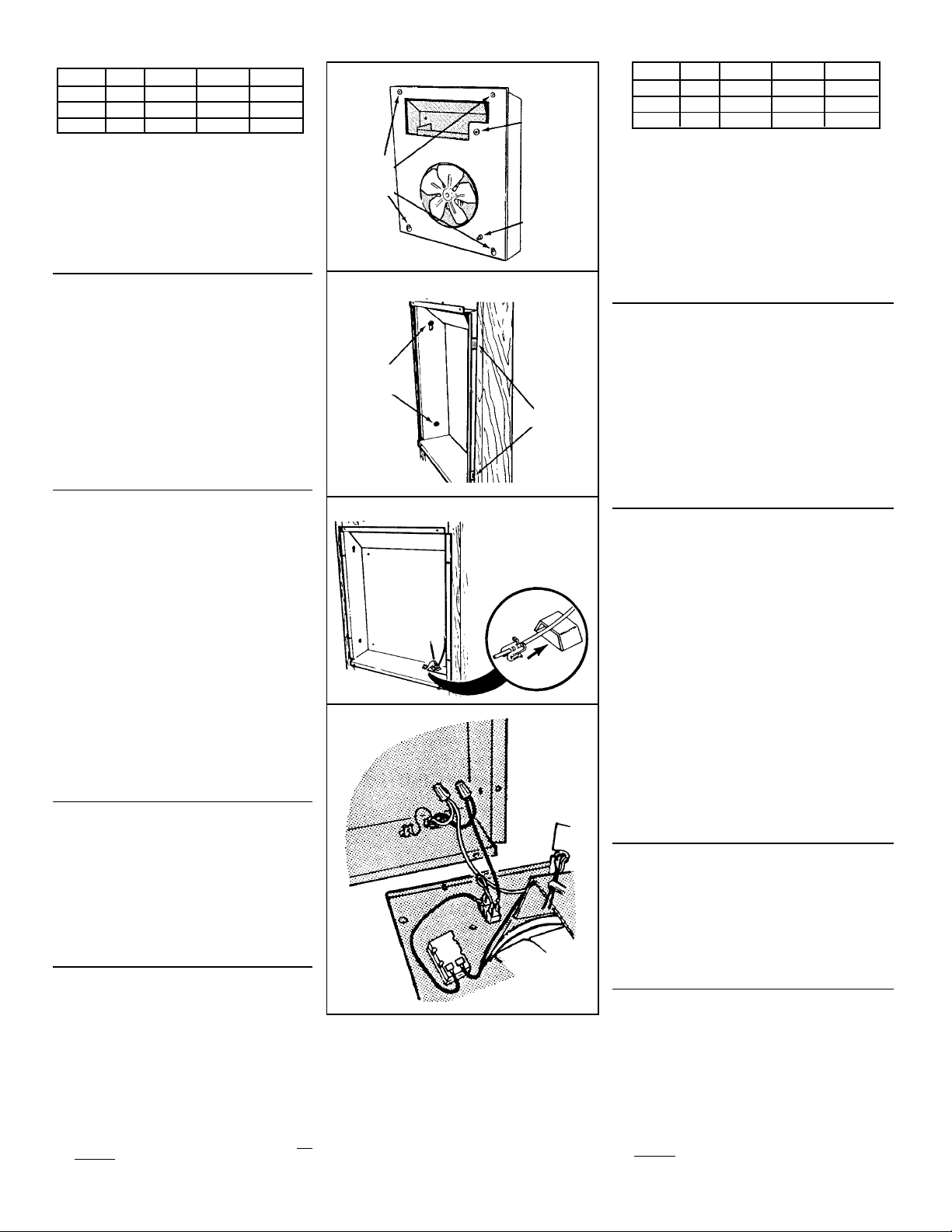
3. Instale la rejilla. (FIG. 8)
Coloque la rejilla sobre el calentador y fíjelo con cuatro
(4) tornillos.
Empuje la perilla en el vástago del termostato.
4. Fije la cubierta de seguridad a la rejilla (opcional).
Cuando se instala el calentador en un área pública sin
un control de pared separado, se recomienda:
1) Graduar el termostato incorporado al nivel de
temperatura deseado.
2) Quitar la perilla del termostato.
3) Fijar la cubierta de seguridad a la rejilla con dos (2)
tornillos, que se proveen.
5. Compruebe el funcionamiento.
Conecte la energía en la entrada de servicio. Active
el termostato en su graduación más alta y compruebe
que se activen el elemento de calor y el soplador.
Luego actívelo en su graduación más baja y
compruebe que se apaguen el elemento y el soplador.
NOTA: El retrasador del ventilador evita que el
ventilador se active hasta que el elemento esté
caliente. Asimismo, mantiene al ventilador en
funcionamiento hasta que el elemento se enfríe.
USO Y MANTENIMIENTO
CUIDADO
DESCONECTE LA ENERGIA EN LA ENTRADA DE
SERVICIO Y ASEGURE EL PANEL ANTES DE
LIMPIAR O DAR SERVICIO A LA UNIDAD.
PROTECTOR DE SOBRECARGA TERMICA
Su calentador cuenta con un protector de sobrecarga térmica
de reposición manual. Si el calentador no funciona cuando
el termostato está activado en su graduación más alta:
* Corte la energía en la entrada de servicio.
* Saque la perilla y la rejilla.
* Oprima el botón “RESET”.
Este tipo de dispositivo es especialmente útil (comparado
con los de reposición automática), ya que alienta al usuario
a encontrar y corregir la causa del sobrecalentamiento de
una unidad al reajustar el protector.
A fin de evitar daños a la propiedad cuando se use este
calentador para evitar congelamientos:
COMPRUEBE que el calentador funciona correctamente
ANTES de dejarlo desatendido.Un protector desconectado
evitará que el calentador opere.
LIMPIEZA
Limpie el calentador con el cepillo redondo de su
aspiradora. Saque las acumulaciones grandes de polvo,
pelusa, etc., que puedan impedir el flujo de aire por el
calentador.
Ese bloqueo disminuirá la eficiencia y creará una posible
condición de sobrecalentamiento.
Para limpiar la rejilla, use un trapo suave humedecido con
limpidador para ventanas.
CUIDADO: LAS PIEZAS METALICAS Y ELECTRICAS
NUNCA SE DEBEN SUMERGIR EN AGUA.
3. Install grille. (FIG. 8)
Place grille over heater and attach with four (4)
screws.
Push knob onto thermostat stem.
4. Attach security cover to grille (optional).
When heater is installed in a public area without
a separate wall control, it is recommended that:
1) Built-in thermostat be set to desired tempera-
ture level.
2) Thermostat knob be removed.
3) Security cover be attached to grille with two
(2) screws, provided.
5. Check operation.
Turn on power at service entrance. Turn thermo-
stat to its highest setting and make sure heating
element and blower come on. Then turn it to its
lowest setting and make sure element and blower
shut off.
NOTE: The fan delay prevents the fan from com-
ing on until the element is hot. Likewise, it keeps
the fan running until the element cools down.
USE AND CARE
CAUTION
DISCONNECT POWER AT SERVICE EN-
TRANCE AND LOCK OUT PANEL BEFORE
CLEANING OR SERVICING UNIT.
THERMAL OVERLOAD PROTECTOR
Your heater is equipped with a manual-reset thermal
overload protector.If heater fails to operate when ther-
mostat is turned to its highest setting:
• Turn off power at service entrance.
• Remove knob and grille.
• Press button marked "RESET".
This type of device is particularly useful (compared to
automatic reset devices) because it encourages the
user to find and correct the cause of overheating unit
when resetting the protector.
To avoid property damage when using this heater to
prevent freeze-ups:
MAKE SURE heater functions properly BEFORE leav-
ing unattended. A tripped protector will prevent the
heater from operating.
CLEANING
Clean the heater using the round brush tool on your
vacuum cleaner. Remove large accumulatoins of dust,
lint, etc., that might impede the flow of air through the
heater. Such blockage will lower its efficiency and cre-
ate a possible overheating condition.
To clean grille, use a soft cloth which has been moist-
ened with household window cleaner.
CAUTION: METAL AND ELECTRICAL PARTS
SHOULD NEVER BE IMMERSED IN WATER.
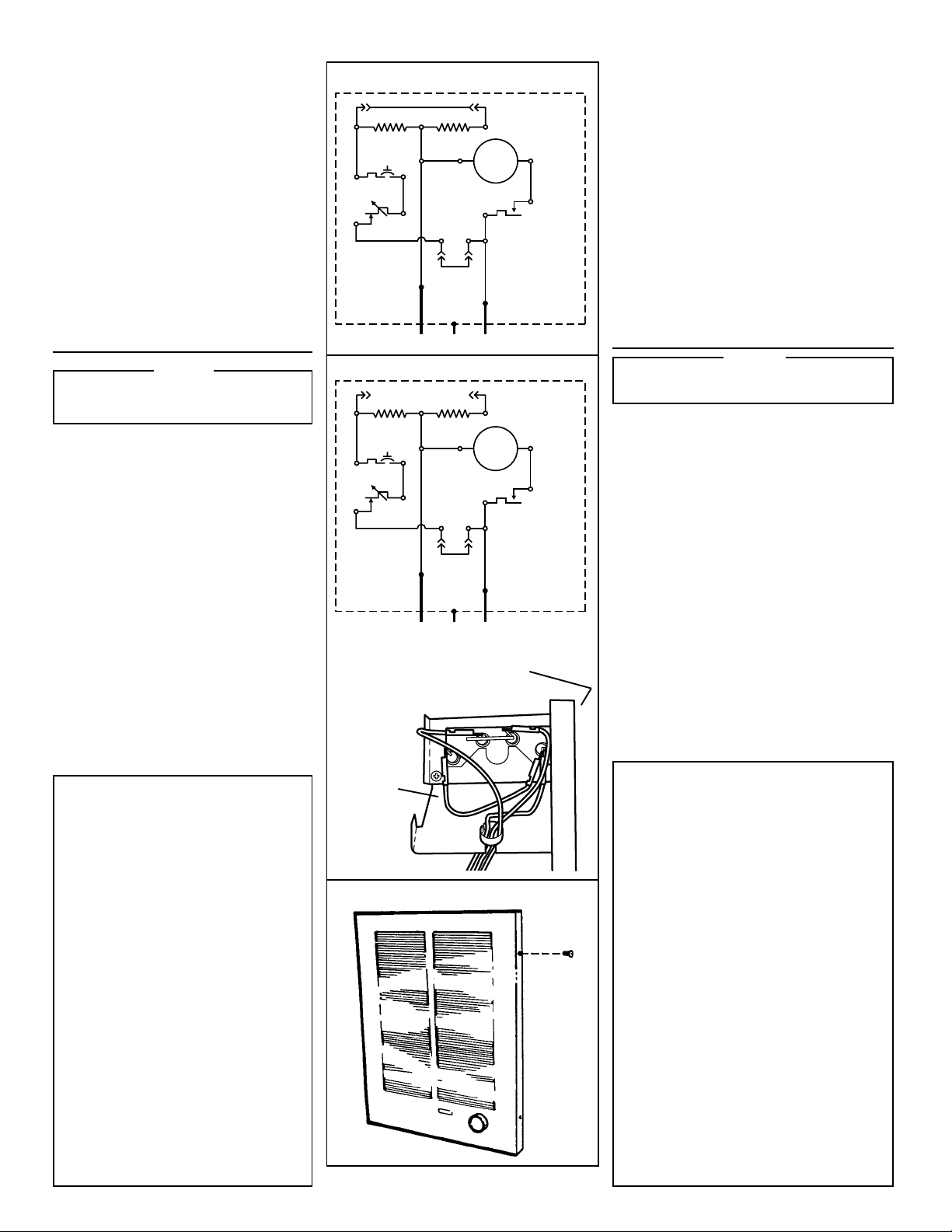
BLACK JUMPER / CABLE DE EMPALME NEGRO
HEATING ELEMENT
ELEMENTO DE CALOR
THERMAL
OVERLOAD
SOBRECARGA
TERMICA
THERMOSTAT
TERMOSTATO
MOTOR
FAN DELAY
RETRASADOR
DEL VENTILADOR
BLACK
NEGRO
BLACK
NEGRO
BLACK
NEGRO
BLACK
NEGRO
BLACK
NEGRO
RED
ROJO
REMOVE JUMPER
FOR REMOTE
THERMOSTAT
QUITARSE EL
CABLE DE EMPALME
PARA TERMOSTATO
REMOTO
T1 T2
T3 T4
FACTORY- WIRED
HEATER
CALENTADOR
CABLEADO EN
FABRICA
240/208 VAC LINE IN LINEA DE ENTRADA, 240/208 VCA
BLACK
NEGRO
BLK
NEG
HEATING ELEMENT
ELEMENTO DE CALOR
THERMAL
OVERLOAD
SOBRECARGA
TERMICA
THERMOSTAT
TERMOSTATO
MOTOR
FAN DELAY
RETRASADOR
DEL VENTILADOR
BLACK
NEGRO
BLACK
NEGRO
BLACK
NEGRO
BLACK
NEGRO
BLACK
NEGRO
RED
ROJO
REMOVE JUMPER
FOR REMOTE
THERMOSTAT
QUITARSE EL
CABLE DE EMPALME
PARA TERMOSTATO
REMOTO
T1 T2
T3 T4
HEATER
CONVERTED TO
HALF-WATTAGE
CALENTADOR
CONVERTIDO A
MITAD DE VATIAJE
240/208 VAC LINE IN LINEA DE ENTRADA, 240/208 VCA
BLACK
NEGRO
BLK
NEG
REMOVE THIS
JUMPER WIRE
QUITE ESTE
ALALMBRE
DE CIERRE
TOP / FRONT OF HEATER
PARTE SUPERIOR / FRENTE
DE CALENTADOR

99042705C
BROAN MFG. CO. INC./A NORTEK COMPANY HARTFORD, WISCONSIN 53027
KEY PART DESCRIPTION DESCRIPCION
NO. NUMBER
NUMERO NUMERO
DE CODIGO DE PIEZAS
1 97009334 Housing
2 99390015 Grounding Clip
3 99030190 Fan Delay
4 98006989 Element Bracket (2 Required)
5 992701155 Heating Element (Model 192)
99270723 Heating Element (Model 194)
99270724 Heating Element (Model 198)
6 99400061 Bushing
7 97008688 Black Wire Assembly (29–1/2")
8 97008690 Black Jumper Wire (2 Required)
9 * Thermal Overload Bracket
10 * Thermal Overload
11 97008692 Red Power Wire
12 99150491 Screw, 8–18 x 3/8 Ph. Pan Head (14 Required)
13 97008683 Partition Plate Assembly
14 93270619 Wire Clamp ( 3 Required)
15 99260425 Nut, 8–32 Hex Keps (2 Required)
16 97008687 Black Wire Assembly (12")
17 99150531 Screw, 8–18 x 5/8 Ph. Pan Head (2 Required)
18 99270720 Terminal Block
19 97008691 Black Power Wire
20 99160350 Screw, 6–32 x 1/4 Ph. Pan Head (2 Required)
21 99030192 Thermostat
22 99080251 Motor (Model 198)
23 99080249 Motor (Models 192 & 194)
24 99020255 Fan Blade
25 97013822 Grille
26 99150478 Screw, 8–18 x 3/8 PH Truss Hd. (4 Required)
27 99090683 Grille Logo
29 99360136 Knob
30 99110687 Security Cover
31 93150462 Screw, 8–18 x 5/8 Oval Head (2 Required)
32 93270493 Cable Tie
* 97013945 Assembly, Thermal Overload (Includes Key
Nos. 9, 10, & 12 (2))
Order replacement parts by "PART NUMBER" — NOT by "KEY NO."
Encargue piezas de repuesto por "NUMERO DE PIEZAS" - NO por "NUMERO DE CODIGO"
Caja
Sujetador de toma de tierra
Retraso de ventilador
Soporte del elemento (Se requieren 2)
Elemento de calefacción (Modelo 192)
Elemento de calefacción (Modelo 194)
Elemento de calefacción (Modelo 198)
Manguito aislador
Conjunto de alambre negro (29 1/2" o 74,93 cm)
Alambre de puente (Se requieren 2)
Soporte de sobrecarga térmica
Sobrecarga térmica
Alambre de energía rojo
Tornillo phillips, cabeza grande. 8-18 x 3/8 (se requieren 14)
Conjunto de placa de separación
Sujetador del alambre (se requieren 3)
Tuerca, Keps hexagonales de 8-32 (se requieren 2)
Conjunto de alambre negro (12", o 30,48 cm)
Tornillo phillips, cabeza grande 8-18 x 5/8 (se requieren 2)
Bloque de terminal
Cable de energía negro
Tornillo, cabeza móvil ph 6-32 x 1/4 (se requieren 2)
Termostato
Motor (Modelo 198)
Motor (Modelos 192 y 194)
Paleta de ventilador
Rejilla
Tornillo de ranura, 8-18 x 3/8 PH Truss Hd. (se requieren 4)
Logotipo de rejilla
Perilla
Cubierta de seguridad
Tornillo, cabeza ovalada 8-18 x 5/8 (se requieren 2)
Enlace de cable
Conjunto de sobrecarga térmica (Incluye Numero de Codigo 9,
10, y 12 (2))
SERVICE PARTS
MODELS 192, 194 & 198
PIEZAS DE SERVICIO
MODELOS 192, 194 y 198
Other manuals for 192
2
This manual suits for next models
2
Other Broan Heater manuals
Popular Heater manuals by other brands

Stahls Hotronix
Stahls Hotronix MAXX Series Operator's manual

Zibro
Zibro SRE 160 TC operating manual

Russell Hobbs
Russell Hobbs RHMFHO1 Installation manual and operating instructions

Pinnacle
Pinnacle ProTemp PT-80-OFR User's manual & operating instructions

Sun2Solar
Sun2Solar MLR-T91-SD01 instruction manual

Purmo
Purmo BH 300 Assembly instructions