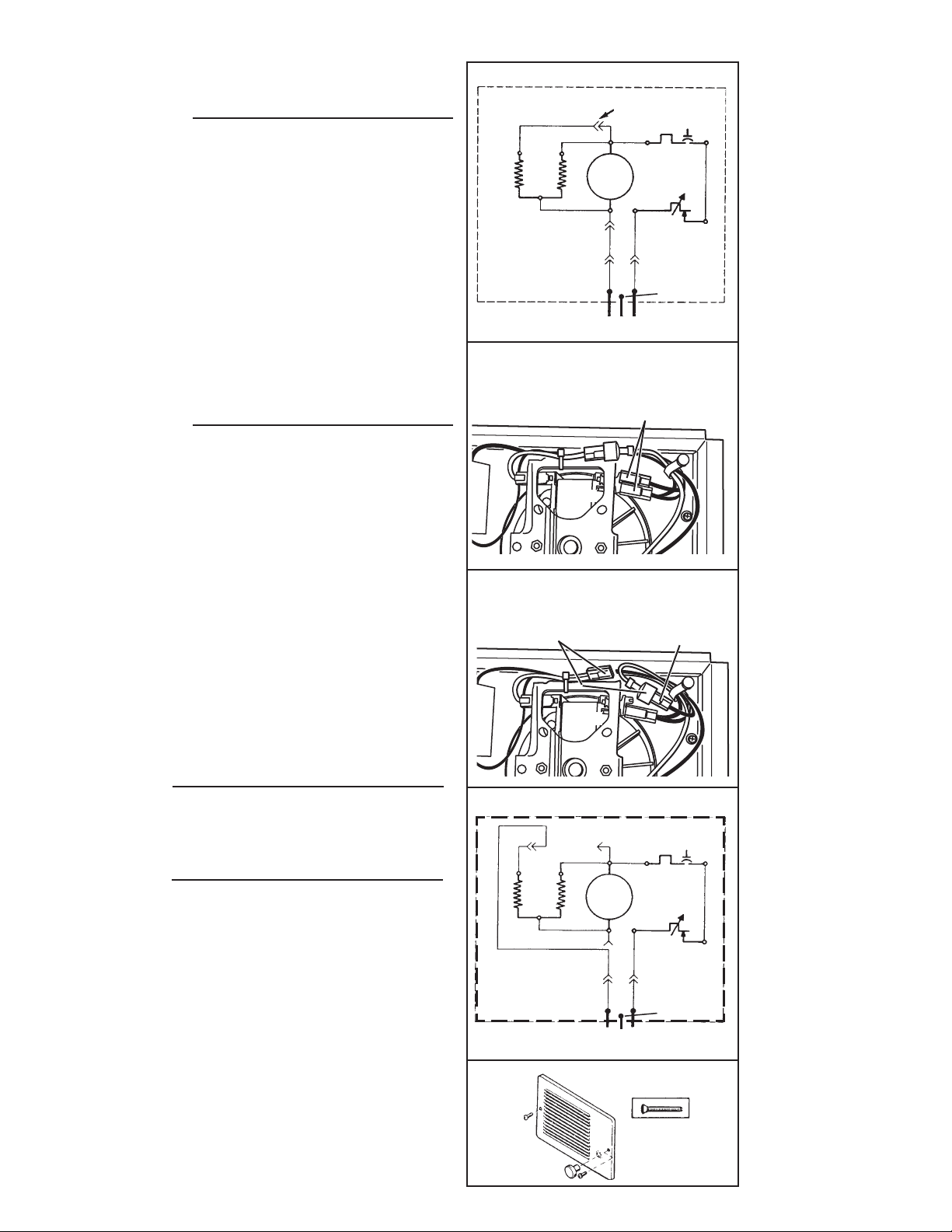
Broan NuTone 174178170 User manual

READ AND SAVE THESE INSTRUCTIONS
FAN-FORCED WALL HEATER
IMPORTANT INSTRUCTIONS
READ ALL INSTRUCTIONS BEFORE
INSTALLING OR USING THIS HEATER.
To reduce the risk of fire, electric shock, or injury to persons,
observe the following:
1. Use this unit only in the manner intended by the manufacturer.
If you have questions, contact the manufacturer at the address or telephone number listed in the warranty.
2. Before servicing or cleaning unit, switch power off at service
panel and lock the service disconnecting means to prevent power from being switched on accidentally. When the service
disconnecting means cannot be locked, securely fasten a prominent warning device, such as a tag, to the service panel.
3. Installation work and electrical wiring must be done by a
qualified person(s) in accordance with all applicable codes and standards, including fire-rated construction codes and
standards.
4. When cutting or drilling into wall or ceiling, do not damage
electrical wiring and other hidden utilities.
5. This heater is hot when in use. To avoid burns, do not let bare
skin touch hot surfaces. Keep combustible materials, such as furniture, pillows, bedding, papers, clothes, etc. and curtains at least 3
feet (0.9 m) from the front of the heater.
6. Extreme caution is necessary when any heater is used by
or near children or invalids and whenever the heater is left operating and unattended.
7. Do not operate any heater after it malfunctions. Disconnect
power at service panel and have heater inspected by a reputable electrician before reusing.
8. Do not use outdoors.
9. To disconnect heater, turn controls to off, and turn off power
to heater circuit at main disconnect panel (or operate internal disconnect switch, if provided).
10. Do not insert or allow foreign objects to enter any ventilation or
exhaust opening, as this may cause an electric shock or fire, or damage the heater.
11. To prevent a possible fire, do not block air intakes or exhaust in
any manner.
12. A heater has hot and arcing or sparking parts inside. Do not use
it in areas where gasoline, paint, or flammable vapors or liquids are used or stored.
13. Use this heater only as described in this manual. Any other use
not recommended by the manufacturer may cause fire, electric shock, or injury to persons.
14. Install heater at least 6 inches from floor or any adjacent wall.
15. To avoid electrical shock: Do not install unit in a tub or shower
enclosure or any location where it may come in contact with water. Never place a switch where it can be reached from a tub or shower.
16. This product may ONLY be installed horizontally in a wall. Do
not mount in any other position.
17. Do not connect heater to dimmer switch or speed control.
18. This product must be grounded.
SAVE THESE INSTRUCTIONS

PLANNING
This heater is intended to be used to suppply
supplemental heat from a wall location in new or
existing construction.
The heater can be operated using its built-in ther-
mostat or a remote thermostat (Broan Model 86W
Line-Voltage Thermostat - purchase separately).
Plan to supply the heater with proper line voltage
and appropriate power cable.
NOTE: Power can be tapped from a nearby circuit
depending on the heater wattage required and the
amperage rating of the circuit.
The table below lists the ratings for each model.
MODELS VOLTS AMPS WATTS BTU/HR
170 120 8.33/4.16 1000/500 3413/1707
240 4.16 1000 3413
208 3.61 750 2560
174 120 12.5/6.25 1500/750 5120/2560
240 6.25 1500 5120
208 5.41 1125 3840
178 240 8.33/4.16 2000/1000 6827/3413
208 7.21/3.61 1500/750 5120/2560
BOLD ratings are factory wired. See “OPTIONAL
WIRING CONVERSIONS” section on page 3 for
wattage and voltage conversion instructions.
Heater can be converted to half-wattage to avoid
overloading such circuits.
Follow these basic steps when installing this heater.
• Nail housing to studs.
• Connect power cable.
• Fasten heater assembly and grille to housing.
(FIG. 1)
FIG. 1
GRILLE
BUILT-IN
THERMOSTAT
WALL
STUD
POWER
CABLE
HEATER
HOUSING
DRYWALL

INSTALLATION
WARNING:To reduce the risk of fire, do not store or
use gasoline or other flammable vapors and liquids
in the vicinity of the heater.
CAUTION: High temperature, risk of fire, keep
electrical cords, drapery, furnishings, and other
combustibles at least 3 feet (0.9 m) from the front of
the heater and away from the side and rear.
1. Remove the retaining screw, unplug wiring harness
and lift heater assembly from housing. (FIG. 2)
2. Slide the wiring cover out of housing. (FIG. 3)
(16”-ON-CENTER STUDS ONLY)
1. Choose which side of housing will be mounted
directly to a wall stud. Then, insert a mounting
bracket, from the opposite side, into the channel
at the top of housing. (FIG. 4)
NOTE: Locate housing at least 6” from the floor and
any adjacent walls.
2. Use measuring guide on side of housing to posi-
tion housing so that it will be flush with finished
wall. Drive two (2) nails through the holes in side
of housing and into stud. (FIG. 5)
3. Extend mounting bracket, level housing, and nail
to other stud. (FIG. 6)
(24”-ON-CENTER STUDS ONLY)
1. Choose which side of housing will be mounted di-
rectly to a wall stud. From this side, push a mounting
bracket as far as possible into the channel at the
top of housing. (FIG. 4)
NOTE: Locate housing at least 6” from the floor and
any adjacent walls.
2. Use measuring guide on side of housing to posi-
tion housing so that it will be flush with finished
wall. Drive two (2) nails through the holes in side
of housing and into stud. (FIG. 5)
3. Secure the two (2) mounting brackets together (with
screw supplied). Level housing and nail to opposite
stud, as shown. (FIG. 7)
WIRING
Installation work and electrical wiring must be
done by a qualified person(s) in accordance with
all applicable codes and standards, including fire-
rated construction codes and standards.
(ALL INSTALLATIONS)
1. Feed electrical power cable through open knockout
in corner of housing and attach with appropriate
connector. Allow 6” of wire inside of housing.
NOTE: Use other housing knockout when wiring
units in parallel.
2. Connect black to black, white to white, green to
green or bare wire. Replace wiring cover. (FIG. 8)
FIG. 2
FIG. 3
FIG. 4
FIG. 5
MEASURING
GUIDE
FIG. 6
FIG. 7
MEASURING
GUIDES
NAIL
HERE

FIG. 9
FIG. 12
BLK
BLK BLK
DISCONNECT FOR HALF-
WATTAGE
THERMAL
OVERLOAD
BLK
BLK
THERMOSTAT
WHT
WHT
WHT
BLK BLK
BLK
BLK
M
WHT
WHT
WHT
WHT
THERMOSTAT
THERMAL
OVERLOAD
WHT
FIG. 13
HEATING
ELEMENT
M
BLK
FACTORY-WIRED
HEATER (FULL
WATTAGE)
LINE IN LINEA
HEATING
ELEMENT
BLK
CONVERTED 240 VAC
HEATER
OPTIONAL WIRING
CONVERSIONS
1. Conversion to half-wattage. (FIGS. 9 & 10)
The heater will produce less heat and use less
electricity if converted to half-wattage.
Disconnect ONE of the two (2) black wires (with
insulated terminals) from the motor.
2. 120 VAC to 240VAC Conversion (FIGS. 11 & 12)
(Factory-wired 120 VAC Models 170 and 174 ONLY)
These heaters can be converted to operate on
240 VAC.
1) Disconnect ONE of the two (2) black wires (with
insulated terminals) from the motor.
2) Disconnect the two (2) white wires (with insu-
lated terminals) from each other. Do not remove
the white wire from beneath plastic wire tie.
3) Connect the black wire to the white wire.
NOTE: When heater is converted from 120 VAC to
240 VAC, half-wattage conversion is not possible.
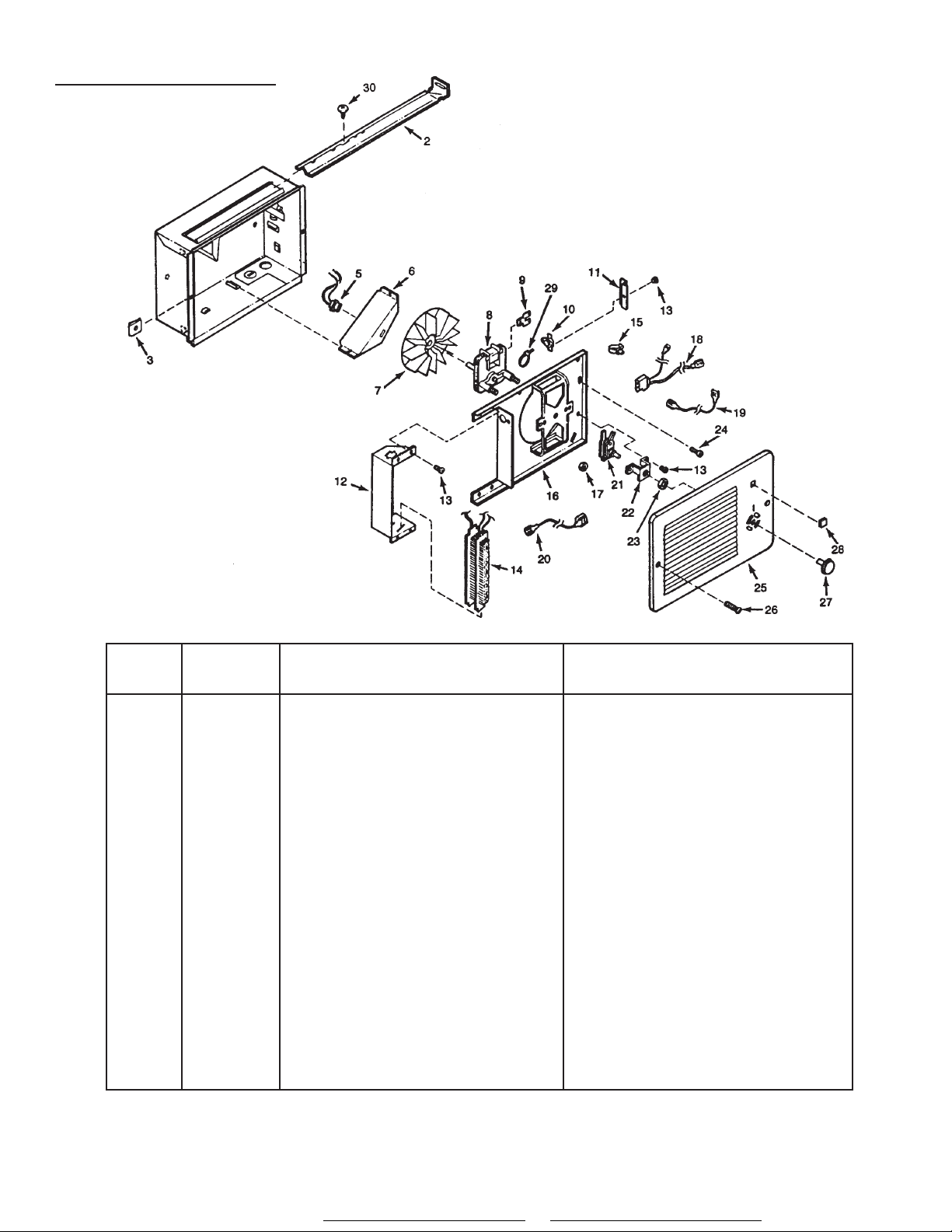
COMPLETE
INSTALLATION
(NEW CONSTRUCTION)
1. A housing mask has been provided to keep
construction dust, drywall spray, paint, etc.
from damaging heater.
Bend the flaps on the mask and push it into
the heater housing.
NOTE: Mask can be put in place before or
after heater assembly is re-installed.
2. Remove mask before operation.
(ALL INSTALLATIONS)
3. Secure heater assembly with retaining screw
and plug wiring harness into receptacle.
4. Fasten grille to heater with two (2) screws
provided. (FIG. 13)
5. Push knob onto thermostat stem.
6. Turn on power at service entrance. Turn
thermostat to its highest setting and make
sure heating element and blower come on.
Then make sure element and blower shut off
at lowest thermostat setting.
FIG. 10 - HALF-WATTAGE CONVERSION
(2) BLACK WIRES (connected to motor)
MOTOR
FIG. 11 -120VAC TO 240VAC CONVERSION
BLACK WIRE (from motor)
WHITE WIRES
MOTOR
GROUND
GROUND
240 VAC LINE IN
OPERATION
Before using heater, make sure heater has been
properly installed according to installation steps
beginning with the "PLANNING" section on page 1.
MAINTENANCE
THERMAL OVERLOAD PROTECTOR
If heater fails to operate when thermostat is turned
to its highest setting: Turn power off at service en-
trance. Remove knob and grille and press button
marked “RESET”.
LUBRICATION
The heater is permanently lubricated and never
needs oiling or disassembly.
CLEANING
Clean heater once a month as follows:
1. Turn off power at service panel.
2. Make sure heating element is cool.
3. Use a soft brush attachment to gently vacuum
grille openings or wipe grille clean with a soft
cloth.
4. Restore power.
CAUTION: METAL AND ELECTRICAL PARTS
SHOULD NEVER BE IMMERSED IN WATER.

SERVICE PARTS
FAN-FORCED WALL
HEATERS
KEY NO. PART NUMBER DESCRIPTION DESCRIPCION
2 98003036 Mounting Bracket (2 Required)
3 99260512 #8-18 Sheet Metal Nut (2 Required)
5 97005422 Receptacle Assembly
6 98006975 Wiring Cover
7 99020130 Blower Wheel
8 99080248 Motor (Models 170 & 174)
99080252 Motor (Model 178)
9 99270735 Tab Adaptor
10 99030194 Thermal Overload
11 99271091 Guard
12 98006974 Element Bracket
13 99150491 Screw, #8-18 x 3/8 Ph. Pan Head (7 Required)
14 99270741 Heating Element (Model 170)
99270725 Heating Element (Model 174)
99270742 Heating Element (Model 178)
15 93270619 Wire Clamp
16 97008682 Partition Plate Assembly
17 99260428 Nut, #6-32 x 5/16 Keps (2 Required)
18 97008675 Plug Assembly
19 97008677 Thermostat Wire Assembly
20 97008678 Overload Wire Assembly
21 99030191 Thermostat
22 98006973 Thermostat Bracket
23 99260464 Lock Nut
24 99150533 Screw, #8-18 x 5/8 Ph. Pan Head
25 98006970 Grille
26 99150528 Grille Screw (2 Required)
27 99360135 Knob
28 99090681 Grille Logo
29 93270493 Wire Tie
30 99150470 Screw, #8-18 x 3/8 Ph. Truss Hd.
Always order replacement parts by" PART NUMBER" - NOT "KEY NUMBER".
Learn more about other home heating & cooling by Broan-NuTone on our website.
Table of contents
Other Broan Heater manuals
Popular Heater manuals by other brands

Grill'D
Grill'D Cometa 180 EU Vega Short Installation and operation manual

Toyostove
Toyostove DR-86 Operating and maintenance instructions

Herschel
Herschel Select Series Installation & operating instructions

Viessmann
Viessmann Vitoplanar EC4 Series operating instructions

Pro-Elec
Pro-Elec PELL0213 manual

Frico
Frico PL1006 manual