Broil King PATIO BASE BL26P-2 User manual

Page 1
Patio Base Kit
Retain owneR’sManual foR futuRe RefeRence.
BL26P-2
SS26P-2
BL48G-2
SS48G-2
PREMIUM GRILLS
in-GRound Post

B102250-1-0714Page 2
IMPORTANT INFORMATION
IMPORTANT
This manual should be read thoroughly by the installer and by anyone who will use
or maintain the grill.
Installer - Write the model number, serial number, and date of installation in the manual.
If available, attach a copy of the receipt. Leave this manual with the grill owner.
Grill Owner - Read and retain this manual. It contains instructions on using and
maintaining your grill, plus information on ordering replacements parts. Attach a
copy of your receipt to this manual. Your receipt established the proof of purchase
required for warranty replacement parts.
WARNING
Follow the instruction in this manual for proper installation and maintenance of the
grill. Improper installation, adjustment, alteration, service or maintenance can cause
injury or property damage. For assistance or additional information consult a
qualied installer, service agency or the gas supplier.
WARNING: FOR YOUR SAFETY
Do not store or use gasoline or other ammable vapors or liquids in the vicinity of
this or any appliance.
CAUTION:
Parts may have sharp edges. Wear leather work gloves and handle parts carefully
during unpacking, assembly and installation.

B102250-1-0714 Page 3
Thank you for purchasing a Broilmaster Grill Post Accessory.
Broilmaster takes pride in its reputation as the The Most Durable Grill Known to Man.
From its thick aluminum casting to its massive cooking grids, your
Broilmaster is built to last. In fact we still make replacement parts for
Broilmaster grills built more than 30 years ago.
Visit www.broilmaster.com and click on the Hall of Fame to see a
sampling of our long-time customers. We hope you enjoy years of
great meals prepared on your Broilmaster. And we hope to add your
photo to the Hall of Fame one day.
Thank You!
Broilmaster is a registered trademark of
Empire Comfort Systems, Inc.
918 Freeburg Ave.
Belleville, Illinois 62220
Telephone 800-851-3153

B102250-1-0714Page 4
Y
ou have chosen the nest grill for your outdoor cooking pleasure.
Please take time to read this entire manual before assembling your Broilmaster
Grill Accessory.
TABLE OF CONTENTS
ASSEMBLY INSTRUCTIONS ..................................................................................................
5
IMPORTANT INFORMATION ..................................................................................................
6
BL48G-2, SS48G-2 IN-GROUND POST SECTION .........................................................
7 - 16
IN-GROUND POST PARTS DIAGRAM....................................................................................
8
POST HARDWARE PACK - B101999......................................................................................
9
INSERT FLEX LINE THROUGH ............................................................................................
10
PLACE POST IN GROUND ...................................................................................................
11
ATTACH UPPER BRACKET ..................................................................................................
12
GREASE CUP HOLDER PLACEMENT.................................................................................
13
ATTACH BOTTOM CASTING TO POST................................................................................
14
ATTACH POST COVER PLATE UPPER BRACKET (R3 ONLY) ...........................................
15
GREASE CUP AND ACCESS DOOR PLACEMENT .............................................................
16
BL26P-2, SS26P-2 PATIO BASE SECTION ..................................................................
17 - 27
PATIO BASE PARTS DIAGRAM ............................................................................................
18
PATIO BASE HARDWARE PACK - B102255.........................................................................
19
ATTACH LOWER BRACKET..................................................................................................
20
ATTACH BASE TO POST ......................................................................................................
21
INSERT FLEX LINE THROUGH POST..................................................................................
22
ATTACH UPPER BRACKET ..................................................................................................
23
GREASE CUP HOLDER PLACEMENT.................................................................................
24
ATTACH BOTTOM CASTING TO POST................................................................................
25
ATTACH POST COVER PLATE UPPER BRACKET (R3 & R3B ONLY)................................
26
GREASE CUP AND ACCESS DOOR PLACEMENT .............................................................
27
GRILL MAINTENANCE HISTORY ................................................................................. 28 - 30
MASTER PARTS DISTRIBUTOR LIS
T................................................................................. 31
HOW TO ORDER REPAIR PARTS
........................................................................................ 31

B102250-1-0714 Page 5
Before You Begin
All Broilmaster grills require some assembly. For the best results, follow the step-by-step instructions.
For natural gas grills, have your gas supplier run service to the desired location first.
If you purchased an accessory with your Broilmaster, follow the instructions provided.
Compare the parts in the box to the parts list provided in this manual. If any are missing, contact your
Broilmaster dealer before beginning assembly.
CAUTION:
Parts may have sharp edges. For your safety
wear leather work gloves and handle parts
carefully during unpacking and assembly.
TOOLS
REQUIRED
3/8” and 7/16”
REQUIRED
3/8” and 7/16”
REQUIRED
7/16”
REQUIRED
5/16”
REQUIRED
ASSEMBLY INSTRUCTIONS

B102250-1-0714Page 6
your Broilmaster dealer.)
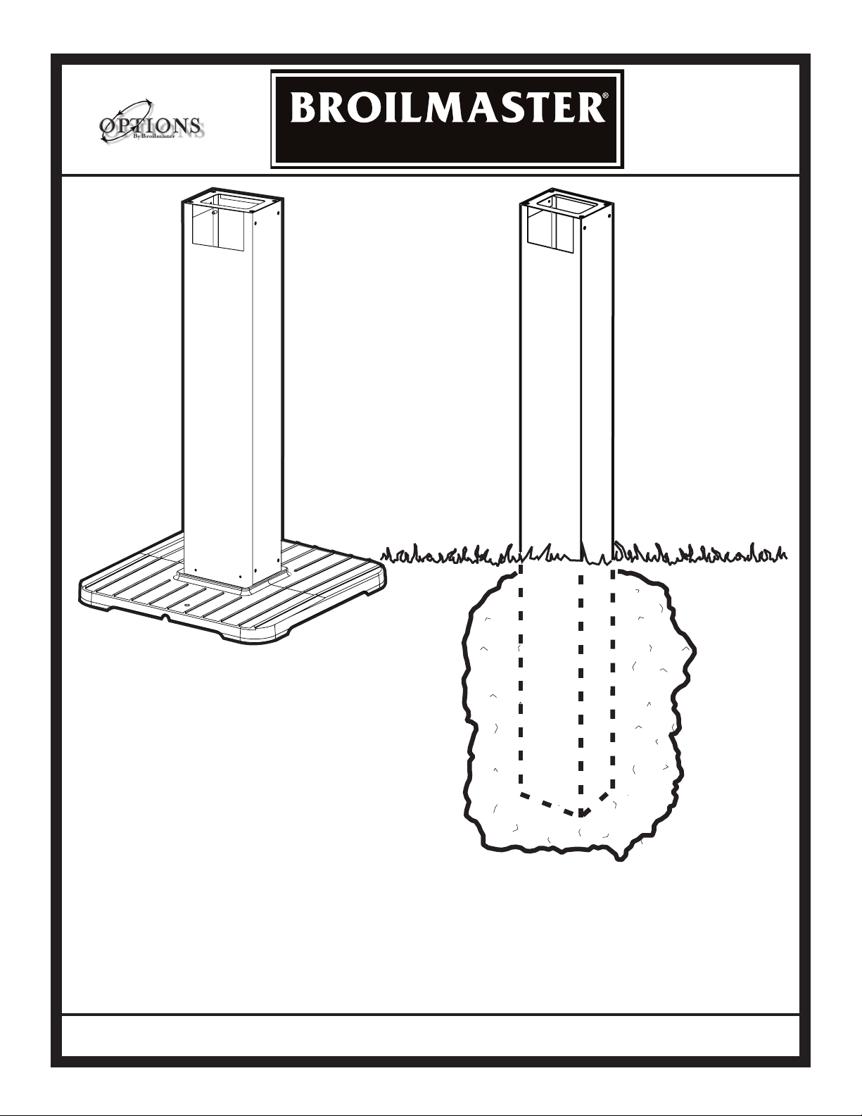
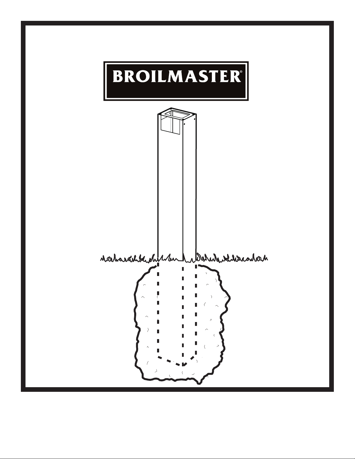
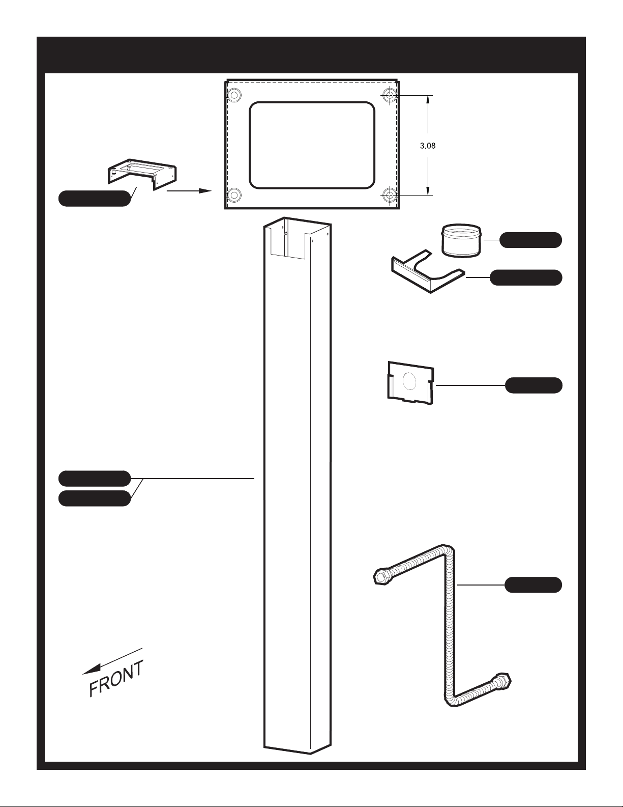
Installing old grill head P3 or P4 to new in-ground post. A
B101668 kit will need to be used to cover the opening in the post.
See instructions with the kit for further installation information.
CAUTION
The grill and its individual shutoff valve must be discon-
nected from the gas supply piping system during any
system pressure testing at test pressures in excess of
1/2 PSIG.
CAUTION
The grill must be isolated from the gas supply piping sys-
tem by closing its individual manual shutoff valve during
any pressure testing of the gas supply piping system at
test pressures equal to or less than 1/2 PSIG.
Cleaning
The exterior of your cart or post may be cleaned with hot water
and mild detergent as needed.
Touch-up paint is available through your Broilmaster® dealer.
Stainless steel surfaces may be cleaned with a spray-on stain-
less steel cleaner available at most hardware stores.
Important: Do not use harsh or abrasive cleaners! Your cart or
post has a highly polished surface and may be easily scratched.
Periodic Inspection and
Maintenance
Periodic inspections and maintenance are essential. All Broil-
master Grill products or mechanical devices eventually begin
to wear due to environment, contaminants, corrosion or aging.
Inspect all components at least twice per year and replace any
that show wear.
If any parts are damaged or missing, you may order parts from
your local Broilmaster®dealer. Please refer to the Parts Dia-
gram and Parts List sections of this manual for more detailed
information.
Grill Location
This grill is designed for outdoor use only.
Never operate your grill in any building, garage, or other
enclosed area. Never operate your grill in a recreational vehicle
or boat. Never operate your grill under any combustible materials,
such as carports, covered porches, awnings, or overhangs.
CAUTION
Keep the sides of the grill at least 16 inches from any
combustible material. Keep the back of the grill at least
18 inches from any combustible material. Placing a hot
grill too close to a building or other combustible mate-
rial may lead to re, property damage, or personal injury.
Combustible materials include fences, patio furniture,
and your home.
Keep the area around the grill clear to ensure proper ventilation.
WARNING
do not install or operate this grill where gasoline or other
ammable materials are used or stored. Failure to comply
with this warning could result in explosion or re causing
property damage or personal injury.
Gas Type
The type gas required for your grill can be determined from the
product identication label located on the grill’s control panel.
Questions regarding different types of gases should be directed
to your local gas supplier.
CAUTION
Never use Liquid Propane (LP) gas in a grill designed
for Natural gas, or Natural gas in a grill designed for
Liquid Propane gas. Questions regarding different types
of gases should be directed to your local gas company.
Connection Requirements
Broilmaster natural gas grills are not equipped with pressure
regulators. Your gas grill operates at a manifold pressure of
seven inches water column. (Your natural gas technician will
understand what this means.)
Arrange with your local gas company or licensed contractor to
have a gas supply line connected to the inlet of the stainless
steel ex tube assemble. The gas supply must have a shutoff
valve that is close to the post in case of emergency and must
be shutoff when the grill is not in use.
Connect your grill this coupling using the twelve foot exible
hose with a quick disconnect tting (available for purchase from
IMPORTANT INFORMATION

Page 7
BL48G-2, SS48G-2
ONE PIECE IN-GROUND POST
PREMIUM GRILLS
BL48G-2, SS48G-2 IN-GROUND POST SECTION

B102250-1-0714Page 8
B101473 (1)
GREASE CUP
B076519 (1)
FLEX LINE
B101760 (1)
UPPER BRACKET ASSEMBLY
B101628 (1)
GREASE CUP HOLDER
B101630 (1)
POST ACCESS DOOR
B101674 (1)
POST ASSEMBLY, SS
B101672 (1)
POST ASSEMBLY, BLACK
IN-GROUND POST PARTS DIAGRAM

B102250-1-0714 Page 9
POST HARDWARE PACK - B101999
Standard hardware items such as bolts, screws, washers, and nuts can be purchased at your local hard-
ware store. Do not order individual pieces of standard hardware. A replacement hardware pack may be
ordered using the hardware pack part number at the top of the page.

B102250-1-0714Page 10
Do not attempt to cut or alter the flex
tube in any way.
At the access door connect a 3/8" flare
coupling (not supplied by Empire) to the
gas supply line and stainless steel
tubing. Position the tubing in the top
notch of the post. Bend the flex tube at
the top end to match the Feed Line of the
grill valve.
Note: Use pipe thread sealant or Teflon
tape at the threads of each connection
being careful to not allow any of these
materials into the flare seat. Test for gas
leaks as directed by the grill's Owners
Manual
Arrange with your local gas company or
licensed contractor to have a gas supply
line connected to inlet of stainless steel
flex tube assembly.
The gas supply line should be installed
according to local codes to prevent
damage from digging.
CAUTION: The gas supply line must be
regulated (In the case of Natural gas that
means connected after your gas meter and
regulator) and that you have an easily
accessible shut-off valve.
WARNING: Do not SUPPLYLP GAS to a
grill designed for NATURAL GAS or
NATURAL GAS designed for LP GAS.
Patio Post, BL26P or Ss26
posts, skip to page 13.
INSERT FLEX LINE THROUGH

B102250-1-0714 Page 11
24 3/4”
ABOVE GRADE
GAS SUPPLYLINE
1. Dig a posthole approximately 12" in diameter and 28 3/4" in depth at the desired grill location.
Note: "Normal Installation" height is achieved when the top of the 48" post is 24 3/4" above ground. This
height provides a cooking surface height of approximately 34" above ground when grids are placed in the
high level.
2. Carefully lower the in-ground post into the hole using the following guidelines:
• The upper rectangular cut-out is located near the top of the post and should be above ground
after installation.
• The rectangular cut-out must face in the same direction as the front of the grill.
• Hole depth and post measurements should be checked to ensure desired height.
Note: Make any adjustments at this time.
3. Prepare concrete or a standard pre-mix according to the manufacturer's package directions. Position
the 48" post in the center of the hole. A level should be used when aligning the post to achieve precise
vertical alignment. Hold the post in place while pouring the concrete mixture into the hole around the post.
Keep concrete below gas line hole.
CONCRETE OR
STANDARD
PRE-MIX
SOIL GRADE
Check Local Codes for requirements
concerning buried gas lines.
PLACE POST IN GROUND

B102250-1-0714Page 12
5/16”
ATTACH UPPER BRACKET
HEX HEAD SCREW,
SS,10 X 1/2
B101569 (4)

B102250-1-0714 Page 13
Remove Protective film applied
to Grease Cup Holder prior to
install. Snap Grease Cup Holder
to top of Post.
Use only the supplied Grease Cup or
noncombustible containers for the
Grease Cup (aluminum or tin cans).
GREASE CUP HOLDER PLACEMENT

B102250-1-0714Page 14
7/16”
ATTACH BOTTOM CASTING TO POST
HEX HEAD BOLT
SS, 1/4-20 X 3/4
B063096 (4)
FLAT WASHER,
SS, 1/4 ID X 5/8 OD
B076332 (4)
.

B102250-1-0714 Page 15
Remove Protective
Film from Cover
Plate and bend
tabs.
COVER PLATE
PROTECTIVE
FILM SIDE
1
Remove Front Left and Right Screws and
install Cover Plate after head and gas line
is connected. (Head not shown for
clarity)
Cover plate needs to be installed after
head and gas line is connected.
(Head is not Shown for Clarity)
5/16”
Secure the two screws removed.
3
4
2
ATTACH POST COVER PLATE UPPER BRACKET (R3 ONLY)
HEX HEAD SCREW,
SS,10-24 X 1/2
B101569 (2)

B102250-1-0714Page 16
21 3 4
Secure Access Door
with hex-head screw
Slide Grease Cup into
the cutout provided in the Grease
Cup Holder.
5/16”
GREASE CUP AND ACCESS DOOR PLACEMENT
HEX HEAD SCREW,
SS,10-24 X 1/2
B101569 (1)

Page 17
BL26P-2, SS26P-2
PATIO BASE
PREMIUM GRILLS
BL26P-2, SS26P-2 PATIO BASE SECTION

B102250-1-0714Page 18
PATIO BASE PARTS DIAGRAM

B102250-1-0714 Page 19
PATIO BASE HARDWARE PACK - B102255
Standard hardware items such as bolts, screws, washers, and nuts can be purchased at your local hard-
ware store. Do not order individual pieces of standard hardware. A replacement hardware pack may be
ordered using the hardware pack part number at the top of the page.

B102250-1-0714Page 20
5/16”
ATTACH LOWER BRACKET
HEX HEAD SCREW,
SS,10 X 1/2
B101569 (8)
(STAINLESS SERIES ONLY)
This manual suits for next models
3
Table of contents
Other Broil King Grill Accessories manuals

Broil King
Broil King BHA-1 User manual

Broil King
Broil King 60938 User manual

Broil King
Broil King 800050 User manual

Broil King
Broil King BPB26-1 User manual

Broil King
Broil King FKCHAR User manual

Broil King
Broil King 900100 User manual

Broil King
Broil King AND P48 User manual

Broil King
Broil King 1450 User manual

Broil King
Broil King Imperial 490 User manual

Broil King
Broil King FKCHAR User manual