Brompton TESSERA T1 User manual


CONTENTS
Chapter 1 - Introduction 3
Chapter 2 - General Overview 4
Tessera SX40 LED Processor 7
Tessera XDDistribution Unit 9
Tessera M2 LED Processor 11
Tessera S4 LED Processor 13
Tessera T1 LED Processor 15
Chapter 3 - Quickstart 17
Chapter 4 - System Configuration 21
Redundancy Configuration 22
Output Capacity 27
Combining Processors 29
Chapter 5 - Tessera Management Software 30
Chapter 6 - Project Setup 38
Chapter 7 - Fixtures 46
Adding Fixtures To A Project 53
Sub-fixtures 59
Understanding Topology And Association 66
Fixture Layout 72
Chapter 8 - Main Project Screen 77
Canvas View 77
Presets 89
Log 93
Moving Around The Canvas 94
Project Data Export 95
Online View 96
Topology View 98
Chapter 9 - Inputs 99
Input Colour Control 102
Histograms 103
Chapter 10 - Processing 107
Active Area 112
ChromaTune 115
Chapter 11 - Test Patterns 120
Chapter 12 - Global Colour 124
Dark Magic 126
Low End Boost 128
Studio Mode 129
On-Screen Colour Adjustment 130
Chapter 13 - Network 142
Chapter 14 - Live Control 145
DMX Control 152
EDMX Control 153
Tessera Control 154
Chapter 15 - Processor Settings 155
Security 159
Date And Time 160
Fixture Library 161
Preferences 166
1

Crash Management 168
Restore Factory Settings 169
Format Internal Storage 170
Reload Firmware 171
Processor Status 172
About 173
Appendix A - Keyboard Shortcuts 174
Appendix B - Cable Requirements For Tessera SX40 And XD 177
Appendix C - Setting IPAddresses 179
Appendix D - DMXChannel Allocations 183
Appendix E - Warranty 187
Glossary 188
2

CHAPTER 1 - INTRODUCTION
COPYRIGHT
©2012 - 2019 Brompton Technology Ltd. All rights reserved.
TRADEMARKS
Brompton is a registered trademark owned by Carallon Ltd.
All other brand and product names used in this document may be trademarks, registered trademarks or trade
names of their respective holders.
CHANGES
The information and specifications contained within this document are subject to change without notice.
Brompton Technology Ltd reserves the right to make improvements and changes to the hardware and
software described in this document at any time and without notice.
Brompton Technology Ltd assumes no responsibility or liability for any errors or inaccuracies that might occur
in this document.
ABOUT THIS MANUAL
This manual provides all the information required for the correct and safe use of the Tessera processors and
the supplied software.
This revision of the manual was written for Tessera software version: 2.2 published on: 04/06/2019
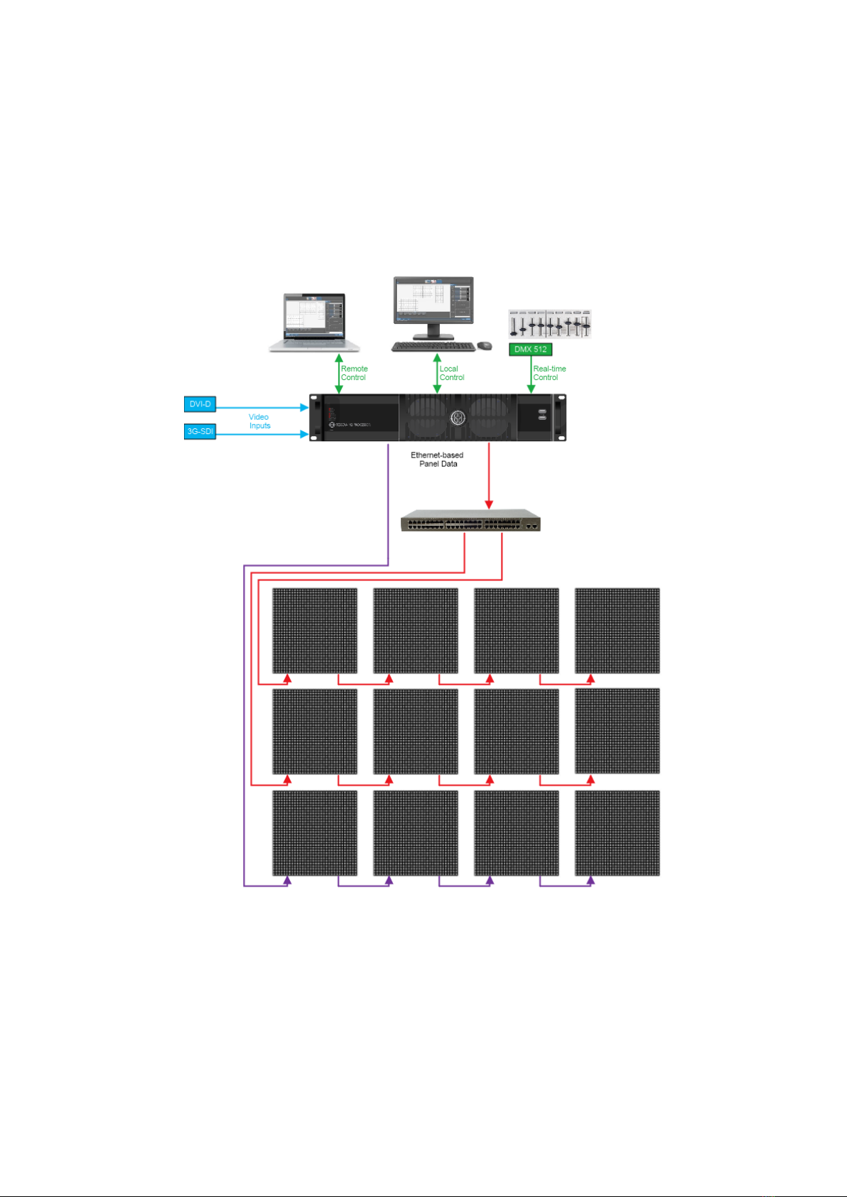
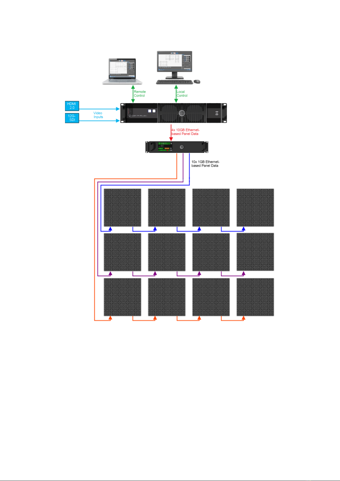
ABOUT THE TESSERA SYSTEM
The Tessera system comprises processors, distribution units, receiver cards and software. These elements can
be used with a wide range of LED fixtures.
Brompton Technology partners with both purchasers and manufacturers who wish to use Brompton
processing to control their LED video products.
For more information about Brompton Technology please contact: info@bromptontech.com
HANDLING AND SAFE OPERATION
The Tessera processors and distribution units are packaged in a rugged custom-designed 19" rack mounting
case with integral mounting handles.
The processor should be adequately supported in a rack at all times. The weight of the processor should never
be supported entirely on the rack ears as this can lead to distortion, especially if the rack is roughly handled.
The processors and distribution units should only be opened by professionals as it will expose the user to
potentially dangerous voltages. The units must never be operated with the cover removed. Opening the units
without an approval from Brompton Technical Support will invalidate the warranty. The product is designed to
operate from a grounded power source between 100 and 250V AC, 47 -63Hz. Ensure the use of a stable power
source. If your power source is prone to surges, place the unit on an uninterruptible power supply (UPS) to
prevent exposure to voltages that could potentially damage the system.
3

CHAPTER 2 - GENERAL OVERVIEW
GENERAL
Brompton Technology makes a variety of Tessera LED video processors for different applications.
Tessera SX40 is currently our highest capacity processor, able to support a nominal 9 million pixels and 4K
canvas resolutions with HDMI 2.0 and 12G SDI inputs. Four 10 Gigabit ports allow data transfer using fibre or
CAT6 copper cable. The SX40 can support up to 2000 connected fixtures and offers maximum flexibility with
the use of the XD distribution system.
Please note: sub-fixtures are supported on Tessera SX40 from firmware version 2.3 and upwards.
Tessera M2 is the most powerful processor to drive HD content. It can control a nominal 2 million pixels over
four 1 Gigabit outputs to a fixture count of up to 2000. Supports 3G-SDI and DVI-I inputs.
Tessera S4 processor is ideal for high resolution screens. The S4 processor does not have the front-side
processing, scaling or degree by degree rotation of the T1 and the M2 but can control the same number of
pixels across four Gigabit outputs as the M2.
Tessera T1 is ideal for creative shows requiring flexibility over number of fixtures. It has a DVI-D input and
supports a capacity of 0.5 million pixels in an HD canvas. The T1 includes most of the main features available
with the Tessera systems, with one output port supporting up to 500 fixtures.
4

SYSTEM OVERVIEW
The Tessera system can be controlled locally using a monitor, keyboard and mouse connected directly to a
Tessera processor. Alternatively, you can use the Tessera Remote software on a Windows PC or Mac connected
to the processor via a Gigabit Ethernet network. The Tessera Remote software can be used in Offline Editor
mode, to allow preparation of project files without a processor.
The processors have an integral DisplayPort (DP++) output and USB ports for local control and monitoring.
Each Tessera output can be distributed using standard Gigabit Ethernet switches or fibre optic transceivers.
SYSTEM SETUP DIAGRAM: TESSERA M2
Figure 2-1. Typical system set-up for a M2 processor (A similar diagram can be applied to S4 and T1)
5

SYSTEM SETUP DIAGRAM: TESSERA SX40
Figure 2-2. Typical system set-up for SX40 processor
6

TESSERA SX40 LED PROCESSOR
FRONT PANEL
Feature Description
Front Panel Status LEDs
Blackout button Sends the output of the processor to black
Freeze button Freezes the output of the processor
Reset button
Press to reset the processor, press and hold to restore to factory settings.
Warning, this will delete all project files and fixture packs not included with the base
firmware.
2 x USB 2.0 type A ports To connect USB memory storage devices and peripherals e.g. keyboard and
mouse
FRONT PANEL STATUS LEDS
LED Name Indication
Active On: Processor in operation
Blinking: Processor booting up
Ethernet The processor is detecting a network connection
Video In The processor is connected to a valid video input source
Tessera Out The processor is connected to fixtures
Reference In The processor has a valid source of genlock connected to the reference input
connector
Overtemp
Off: Processor is in normal operating temperatures
Blinking: Processor overheating but operational
On: Processor overheated and shutdown
7

REAR PANEL CONNECTIONS
Feature Description
Management Ethernet
Connect a PC or Mac running Tessera Remote, Tessera Control applications or an
eDMX protocol directly to the local data Gigabit Ethernet port. The two ports work
as a switch to daisy-chain units.
Local User Interface
Tessera SX40 LED processor can be operated locally with a monitor connected via
DisplayPort. Peripherals such as mouse and keyboard can be connected to the
USB ports on either the front or rear panel.
HDMI Input
A HDMI 2.0 input with support for digital 4k progressive signal up to 4096x2160
@ 60Hz (600MHz pixel clock). See “Canvas Resolutions” on page 42 for more
information.
Reference Input Used for analog bi-level or tri-level sync.
12G-SDI Input
A 12G-SDI input is available. The SDI inputs supports HD-SDI, 3G-SDI level A or
level B, 6G-SDI and 12G-SDI, 2SI format; SQ not supported. 12G-SDI accepts a
progressive signal of up to 4096 x 2160 resolution at 23.98Hz to 60Hz framerate
with 10 bits per channel colour depth.
Loop Thru Ports All video inputs and syncs have re-clocked loop thru ports.
10 Gigabit Ethernet
Outputs
The Tessera SX40 LED processor has four 10 Gigabit outputs which can be used by
plugging an XD unit to distribute the signal. Fixtures should be connected to the
EtherCON connectors in the XD unit with Gigabit Ethernet cable (Cat-5e or above).
See “System Configuration” on page 21 for more information.
DMX512-A Input and Thru For DMX real-time control.
On/Off Switch The processor can be shut down from the local interface or remote computer. No
harm will result from turning the processor off at the switch.
IEC Mains Input The input is auto ranging from 100-250v/47-63Hz.
8

TESSERA XDDISTRIBUTION UNIT
FRONT PANEL
Front Panel Touchscreen
A front touchscreen displays some information for confirmation during setup and troubleshooting. This
includes:
lAll Ethernet port link states
lProcessor connection state
lThe name of the current project open on the Tessera SX40
lXD name for easy identification in large projects
The screen orientation and brightness is configurable, and the screen and per-port LEDs may be disabled for
operating in dark environments.
Firmware is reloadable from the Tessera SX40, just as with other Tessera fixtures.
9

REAR PANEL CONNECTIONS
Feature Description
Two 10G Tessera Protocol
copper inputs for
connection from Tessera
SX40
Supports Neutrik EtherCON Cat 6A / etherCON (CAT5e) connectors
Compatible with standard RJ45 connectors
Requires Cat6A cable (up to 60m) or Cat5e cable (up to 30m)
One of the 10G ports can be used as thru connection for daisy-chaining of
additional XDs
Two 10G Tessera Protocol
fibre inputs for connection
from Tessera SX40 (Single
mode ONLY)
Supports Neutrik opticalCON DUO / DUO ARMORED / DUO X-TREME / DUO LITE
connectors
Compatible with standard LC-Duplex connectors
Requires 1310nm, 9/125um single-mode fibre (up to 2KM) with PC or UPC
connectors
One of the 10G ports can be used as thru connection for daisy-chaining of
additional XDs
Auto-switching between fibre and copper
Thru port auto-switches independently from input
Up to five XDs may be
daisy-chained
Position 1G output ports in multiple locations for cabling convenience
Bandwidth of each 1G port is shared between all daisy-chained XDs
Extend 10G cable lengths using an XD as a signal repeater
Convert between 10G fibre and 10G copper (or vice versa) using an XD as a media
converter
Ten 1G Tessera Protocol
outputs for connection to
fixtures
Neutrik etherCON connectors, compatible with standard RJ45
Each 1G output supports a nominal 525K pixels at 8bpc, 60Hz
Pixel capacity per 1G port scales according to selected bit depth and framerate
10

TESSERA M2 LED PROCESSOR
FRONT PANEL
Feature Description
Front panel status LEDs
Reset button
Press to reset the processor, press and hold to restore to factory settings.
Warning, this will delete all project files and fixture packs not included with the base
firmware
2 x USB 2.0 type A ports To connect USB memory storage devices and peripherals e.g. keyboard and
mouse
FRONT PANEL STATUS LEDS
LEDName Indication
Active On: Processor in operation
Blinking: Processor booting up
Ethernet The processor is detecting a network connection
DMX In A DMXSignal is being received by the processor
Video In The processor is connected to a valid video input source
Reference In The processor has a valid source of genlock connected to the reference input connector
Tessera Out The processor is connected to fixtures
Black/Freeze Either the blackout or freeze button has been enabled
Overtemp
Off: Processor in normal operating temperatures
Blinking: Processor overheating but operational
On: Processor overheated and shutdown
11

REAR PANEL CONNECTIONS
Feature Description
Management Ethernet
Connect a PC or Mac running the Tessera Remote, Tessera Control application or
an eDMX protocol directly to the local data Gigabit Ethernet port. The two ports
work as a switch to daisy-chain units.
Local User Interface
The M2 processor can be operated locally with a monitor connected via
DisplayPort. Peripherals such as mouse and keyboard can be connected to the
USB ports on either the front or rear panel.
DVI Input
A DVI input of up to 1920x1080 @ 60Hz (148.5MHz pixel clock) is supported. This
is a DVI-I input which supports DVI-D, VGA/ RGBHV and Component Analogue
(YPbPr) with a suitable adapter. See “Canvas Resolutions” on page 42 for more
info.
Reference Input Used for analog bi-level or tri-level sync.
3G-SDI Input
Two 3G-SDI inputs are available. Both inputs can be used concurrently as an
independent input. The SDI inputs support 3G-SDI level A or level B. Both inputs
can be used together to support Dual Link HD-SDI.
3G-SDI accepts progressive and interlaced signal of up to 1920x1080 resolution at
23.98Hz to 60Hz framerate with 10 bits per channel colour depth.
Loop Thru Ports All video inputs and syncs have re-clocked loop thru ports.
Gigabit Ethernet Outputs
The M2 processor has four 1 Gigabit Ethernet outputs which are provided on
EtherCON connectors. Fixtures must be connected using Gigabit Ethernet cable
(Cat-5e or above). See “System Configuration” on page 21 for more info.
DMX 512-A Input For DMX real-time control.
On/Off Switch The processor can be shut down from the local interface or remote computer. No
harm will result from turning the processor off at the switch.
IEC Mains Input The input is auto ranging from 100-250v/47-63Hz
12

TESSERA S4 LED PROCESSOR
FRONT PANEL
Feature Description
Front panel status LEDs
Black button Sends the output of the processor to black
Freeze button Freezes the output of the processor
Reset button
Press to reset the processor, press and hold to restore to factory settings.
Warning, this will delete all project files and fixture packs not included with the base
firmware
2 x USB 2.0 type A ports To connect USB memory storage devices and peripherals e.g. keyboard and
mouse
FRONT PANEL STATUS LEDS
LEDName Indication
Active On: Processor in operation
Blinking: Processor booting up
Ethernet The processor is detecting a network connection
Video In The processor is connected to a valid video input source
Tessera Out The processor is connected to fixtures
Overtemp
Off: Processor is in normal operating temperatures
Blinking: Processor is overheating but operational
On: Processor overheated and shutdown
13

REAR PANEL CONNECTIONS
Feature Description
Management Ethernet Connect a PC or Mac running the Tessera Remote, Tessera Control application or
an eDMX protocol directly to the local data Gigabit Ethernet port.
Local User Interface
The S4 processor can be operated locally with a monitor connected via
DisplayPort. Peripherals such as mouse and keyboard can be connected to the
USB ports on either the front or rear panel.
DVI Input
A DVI input of up to 1920x1080 @ 60Hz (148.5MHz pixel clock) is supported. This
is a DVI-D input, with a re-clocked DVI-D thru. See “Canvas Resolutions” on page
42 for more info.
Gigabit Ethernet Outputs
The S4 processor has four 1 Gigabit Ethernet outputs which are provided on
EtherCON connectors. Fixtures must be connected using Gigabit Ethernet cable
(Cat-5e or above). See “System Configuration” on page 21 for more info
On/Off Switch The processor can be shut down from the local interface or remote computer. No
harm will result from turning the processor off at the switch.
IEC Mains Input The input is auto ranging from 100-250v/47-63Hz
14

TESSERA T1 LED PROCESSOR
FRONT PANEL
Feature Description
Front panel status LEDs
Reset button
Press to reset the processor, press and hold to restore to factory settings.
Warning, this will delete all project files and fixture packs not included with the base
firmware
2 x USB 2.0 type A ports To connect USB memory storage devices and peripherals e.g. keyboard and
mouse
FRONT PANEL STATUS LEDS
LED Name Indication
Active On:Processor in operation
Blinking:Processor booting up
Ethernet The processor is detecting a network connection
DMX In A DMXsignal is being received by the processor
Video In The processor is connected to a valid video input source
Tessera Out The processor is connected to fixtures
Black/Freeze Either the blackout or freeze button has been enabled
Overtemp
Off:Processor is in normal operating temperatures
Blinking: Processor is overheating but operational
On: Processor overheated and shutdown
15

REAR PANEL CONNECTIONS
Feature Description
Management Ethernet Connect a PC or Mac running the Tessera Remote, Tessera Control application or
an eDMX protocol directly to the local data Gigabit Ethernet port.
Local User Interface
The T1 processor can be operated locally with a monitor connected via
DisplayPort. Peripherals such as mouse and keyboard can be connected to the
USB ports on either the front or rear panel.
DVI Input
A DVI input of up to 1920x1080 @ 60Hz (148.5MHz pixel clock) is supported. This
is a DVI-D input, with a re-clocked DVI-D thru. See “Canvas Resolutions” on page
42 for more info.
DMX 512-A Input For DMX real-time control.
Gigabit Ethernet Outputs
The T1 processor has one 1 Gigabit Ethernet output which are provided on
EtherCON connectors. Fixtures must be connected using Gigabit Ethernet cable
(Cat-5e or above). See “System Configuration” on page 21 for more info
On/Off Switch The processor can be shut down from the local interface or remote computer. No
harm will result from turning the processor off at the switch.
IEC Mains Input The input is auto ranging from 100-250v/47-63Hz
16

CHAPTER 3 - QUICKSTART
Follow this chapter to get a basic system up and running. This guide covers starting a new project with fixtures
connected. To set up a project offline and connect fixtures at a later stage, see “Tessera Management
Software” on page 30 for more info.
TESSERA PROCESSOR SETUP
1. a. M2, T1 and S4 users: Connect fixtures to the Tessera output ports on the rear panel of the
processor using Gigabit Ethernet cable (Cat 5e or above) and network switches.
b. SX40 users: Connect the XD unit to the processor using either copper or fibre optic cables.
Fixtures are required to be connected to the XD unit.
Note - Tessera SX40 processor does not feature support sub-fixtures. Tessera
firmware version 2.3 will introduce support for sub-fixtures.
2. Connect the video input source(s) to the DVI, HDMI and/or SDI input ports.
3. Connect a monitor to the Local UI using the DisplayPort connector and connect a mouse and keyboard.
Alternatively, access the processor's user interface through a Mac or Windows PC running the Tessera
Remote application.
4. Connect the IEC mains input and switch the processor on. When the processor has powered up, the
monitor displays the start screen. By default, the processor is configured to automatically load the
previous project after a set amount of time if the user does not intervene.
Figure 3-1. The Start Screen
17

TESSERA PROJECT SETUP
1. From the Start Screen, select New to launch the Project Wizard.
Figure 3-2. The New Project Wizard
2. The project name can be manually entered, if no entry is made, a default project name containing the
processor’s model with a date and time stamp is assigned.
3. Select a canvas size from the drop-down menu. When selecting a resolution other than the native
1920x1080, Tessera M2 and T1 processors enforce Low Latency Mode.
4. Click Create to be taken to the Main Project Screen.
5. The project is saved to the processor’s internal storage. When using Tessera Remote, project files are
also saved to the connected computer.
Figure 3-3. Main Project Screen
18

CONNECTING FIXTURES
Figure 3-4. Add Fixtures from Network button
1. Ensure that all fixtures are connected to the processor with the desired topology, taking into
consideration the output port’s capacity limit.
2. Click the Add Fixtures From Network button. The canvas toolbar is replaced with a row of currently
connected fixtures. When using Add Fixtures From Network, strings of fixtures are highlighted with
colours corresponding to the ones shown in the UI. Each string is assigned a unique numeric code which
appears on the first fixture of the string during association.
Figure 3-5. The Add Fixtures From Network toolbar, the right-side shows connected fixtures whilst in Add Fixtures
From Network menu.
3. Entering this code on the processor (using number keys or numpad) selects the corresponding string for
association. The string is then ready to be drawn in the canvas using the cursor.
Figure 3-6. Associating Fixtures
Figure 3-7. A highlighted Recoloured string
4. The first fixture in the string is highlighted white, while other fixtures display varying shades of the same
colour to denote the order of the fixtures in the string - from brightest to darkest.
5. Click on the canvas to add fixtures one by one. The currently selected fixture is highlighted in white on
the LED panel.
19
This manual suits for next models
3
Table of contents
Popular Media Converter manuals by other brands

SMC Networks
SMC Networks LEHF E Series Operation manual

MyTek
MyTek Stereo96 ADC user manual

Williams AV
Williams AV Annotation Pro Plus quick start guide

Hornby
Hornby HM DCC HM7000 Series Full reference manual

Converters.TV
Converters.TV Video to VGA Converters Operation manual

Renishaw
Renishaw ATOM installation guide