manuals.online logo
Brands
  1. Home
  2. •
  3. Brands
  4. •
  5. Brooks
  6. •
  7. Controllers
  8. •
  9. Brooks On-Board IS User manual

Brooks On-Board IS User manual

4 Copyright 2013, Brooks Automation Inc Part Number 8040648, Revision A, 01/11/2013 ECO Number 63723 Brooks Automation www.brooks.com Printed in U.S.A 1
800-367-4887 USA
978-262-2400 International
Host RS-232 Connector
Table 1 provides information for connecting the Host computer to the On-Board IS Controller.
Table 1: Host RS-232 Connector Specifications
Parameter Value
Baud Rate 9.6 kbs
Data Bits 7
Parity Even
Number of Stop Bits 0
NOTE: The Host computer RS-232 cable must be fully shielded through to the outer shell. Use CTI-Cryogenics cable
8132157 or equivalent.
Startup
See the 8040647, On-Board IS Cryopump Operation Instructions, for details.
Status LEDs
Status LED III blinks when the On-Board IS Controller is operating, and indicates normal Intercomponent Network
communication.Status LED I and LED II remain off during normal operation.
Helium Mapping
A helium map is a collection of cryopumps and compressors that the On-Board IS Controller manages, so that the
system operates efficiently. The map controls when each cryopump uses a shared helium manifold and compressor for
each process tool. See the On-Board IS Cryopump System Operation Guide, CTI-Cryogenics part number 8040647,
for more information about helium maps.
To check the device (cryopumps and compressors) addresses in a helium map:
1. Make a physical inventory of the system, noting the address of each device.
2. Use the Remote keypad (part number 8187007K00, see Figure 3) to go to the On-Board IS Controller screen.
3. Choose Monitor and press Enter, choose Show Devices and then press Enter.
4. Ensure that all device addresses appear correctly.
If all device addresses match the physical inventory, continue to add or change a helium map. If the device addresses do not
match, check the cable connections and repeat from Step 2 through this step.
To change or add to a helium map:
1. Use the Remote keypad to go to the On-Board IS Controller screen.
2. Choose System Setup and press Enter, choose Helium and then press Enter, finally choose Helium Map X
(where Xis the number of the helium map you want to see) then press Enter. The Choose Map Pumps
screen appears.
3. Choose the addresses of cryopumps that match your inventory addresses, go to Accept Change, and then
press Enter.The Choose Compressors screen appears.
4. Choose the addresses of compressors that match your inventory addresses, go to Accept Change, and then
press Enter.The Verify Helium Map X screen appears.
5. Go to Accept Change and press Enter to set the helium map.
If you want to make changes to the helium map, press the back button as necessary and make the changes.
Product Information and Technical Support
Please visit the Brooks Automation website at www.brooks.com or email to [email protected].
On-Board®IS Controller (Pump Mount)
Quick Installation Guide
Part Number 8040648, Revision A, 01/11/2013
ECO Number 63723
On-Board IS Controller Specifications
Input Voltage and Power: 24 VDC +/- 10% (21.6 - 26.4) VDC - 18 watts
Ambient Temperature: 50º F - 100º F (10º C - 38º C)
Communication Interface: Host RS-232, Aux RS-232, Service RS-232 - 9 Pin D Connector
Communication Interface Baud Rate: 9600
On-Board IS Intercomponent Network Interface: RS-232, RS-485
On-Board IS Remote Interface: USB B Connector with RS-232 Protocol
2 Copyright 2013, Brooks Automation Inc Part Number 8040648, Revision A, 01/11/2013 ECO Number 63723 Printed in U.S.A 3
Before You Start
1. Ensure the On-Board IS Cryopumps are installed according to the appropriate On-Board IS Cryopump Quick
Installation Guide.
2. Ensure the On-Board IS 1000 Compressors are installed according to 8040645, On-Board IS 1000
Compressor Quick Installation Guide.
3. Read and follow all safety precautions in this guide and in the appropriate cryopump and compressor guides.
On-Board IS Controller Installation
Install the On-Board IS Controller on the selected On-Board IS Cryopump as shown in Figure 1.
Figure 1: On-Board IS Controller Pump Mount Installation
On-Board IS Controller Cable Connections
1. Connect the Channel A Network Cables between the On-Board IS Controller and On-Board IS Cryopumps as
shown in Figure 2 and Figure 3.
2. Connect the Channel B Network Cables between the On-Board IS Controller and On-Board IS Cryopumps as
shown in Figure 2 and Figure 3.
3. Connect the Channel C Network Cables between the On-Board IS Controller and On-Board IS 1000
Compressors as shown in Figure 2 and Figure 3.
NOTE: Make sure the last On-Board IS Cryopump and On-Board IS 1000 Compressor on each channel have a
terminator installed in the open Network connector. Otherwise, data for that channel will not be visible on the On-
Board IS Remote.
4. Connect a Terminator to the open Network terminal on the last On-Board IS device on each channel.
5. Connect the HOST computer RS-232 cable to the HOST connector on the On-Board IS Controller.
6. Connect the On-Board IS Remote cable to the REMOTE connector on the On-Board IS Controller front panel.
7. Connect the power supply power cable to a customer provided 24 VDC power source as shown in Figure 2.
Status III (LED) blinks when the On-Board IS Controller is communicating with the network.
Figure 2: On-Board IS Controller Cable Connections
Figure 3: On-Board IS Cryopump and Network Connections
Equipment Damage
To avoid damaging the equipment, ensure the Network Cables are not near EMI sources when routing
them through the process tool.
REMOVE THE ON-BOARD IS CRYOPUMP BEZEL
REMOVE THE
ALIGN AND INSTALL THE
SECURE THE ON-BOARD IS CONTROLLER
1
2
3
4
NOTE: THE MOUNTING INSTRUCTIONS
WITH THE MODULE SCREW.
WITH THE CRYOPUMP MOUNTING TABS.
ON-BOARD IS MODULE SCREW
AND SAVE FOR RE-USE IN STEP 4.
ARE THE SAME FOR MOUNTING TO THE
LEFT OR RIGHT SIDE OF THE CRYOPUMP
ON-BOARD IS CONTROLLER
REMOVE THE CONTROLLER SCREWS.
BY CAREFULLY PRYING IT OFF OF THE CRYOPUMP.
CHANNEL A - ON-BOARD IS CRYOPUMPS
CHANNEL C - ON-BOARD IS
HOST COMPUTER RS-232
CUSTOMER PROVIDED
(SEE TABLE 1)
ON-BOARD IS REMOTE
P1-1-RED
P1-2-BLACK
P1-3-GREEN
(+) 24 VDC
(-) 24 VDC
GROUND
24 VDC POWER CABLE CONNECTIONS INSET
24 VDC
INPUT
3
2
1
24 VDC (SEE INSET)
P1
CHANNEL B - ON-BOARD IS CRYOPUMPS
1000 COMPRESSORS
ON-BOARD IS 1000 COMPRESSORS
24 VDC
HOST RS-232
?
ON-BOARD IS REMOTE
TERMINATOR
TERMINATOR
023
023
10
TERMINATOR
1
1
ON-BOARD IS CRYOPUMPS
ALL CHANNEL ADDRESSES IN THE SOFTWARE HAVE A
CHANNEL A ADDRESSES = 0X
CHANNEL B ADDRESSES = 1X
CHANNEL C ADDRESSES = 2X
*NOTE
: THIS FIGURE SHOWS THE PHYSICAL ADDRESSES.
NUMERICAL PREFIX:
*CHANNEL A ADDRESSES (0)
*CHANNEL B ADDRESSES (1)
*CHANNEL C ADDRESSES (2)

Other Brooks Controllers manuals

Brooks SLA7810 Series User manual

Brooks

Brooks SLA7810 Series User manual

Brooks 609638 User manual

Brooks

Brooks 609638 User manual

Brooks Granville-Phillips Convectron 316 Series User manual

Brooks

Brooks Granville-Phillips Convectron 316 Series User manual

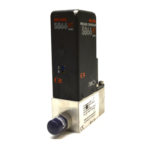
Brooks 5866 User manual

Brooks

Brooks 5866 User manual

Brooks GF Series User manual

Brooks

Brooks GF Series User manual

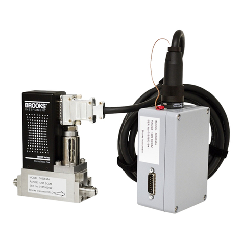
Brooks 5850EMH User manual

Brooks

Brooks 5850EMH User manual

Brooks SLA5810/20 User manual

Brooks

Brooks SLA5810/20 User manual

Brooks 5851i User manual

Brooks

Brooks 5851i User manual

Brooks 5851EM Series User manual

Brooks

Brooks 5851EM Series User manual

Brooks 5850i User manual

Brooks

Brooks 5850i User manual

Brooks 4860 User manual

Brooks

Brooks 4860 User manual

Brooks QMBC User manual

Brooks

Brooks QMBC User manual

Brooks GP200 Owner's manual

Brooks

Brooks GP200 Owner's manual

Brooks SLA7950S User manual

Brooks

Brooks SLA7950S User manual

Brooks GF100 Series User manual

Brooks

Brooks GF100 Series User manual

Brooks MFM User manual

Brooks

Brooks MFM User manual

Brooks SLAMf Series Owner's manual

Brooks

Brooks SLAMf Series Owner's manual

Brooks Electronics RadioLINK EIB450 User manual

Brooks

Brooks Electronics RadioLINK EIB450 User manual

Brooks SLA5810 User manual

Brooks

Brooks SLA5810 User manual

Brooks SLA7840 User manual

Brooks

Brooks SLA7840 User manual

Brooks 4800 Series Owner's manual

Brooks

Brooks 4800 Series Owner's manual

Brooks FAC20 User manual

Brooks

Brooks FAC20 User manual

Popular Controllers manuals by other brands

HID Mercury LP1501 Installations and specifications

HID

HID Mercury LP1501 Installations and specifications

Kobold ZOK-E1 Supplementary operating instructions

Kobold

Kobold ZOK-E1 Supplementary operating instructions

Andover Controls ACC EMX 150 installation guide

Andover Controls

Andover Controls ACC EMX 150 installation guide

Airflow Adroit instruction manual

Airflow

Airflow Adroit instruction manual

Navien H2Air installation manual

Navien

Navien H2Air installation manual

National Instruments CompactRIO NI cRIO-9012 operating instructions

National Instruments

National Instruments CompactRIO NI cRIO-9012 operating instructions

AVE Domus 100 SISTEMA44 441048M quick start guide

AVE

AVE Domus 100 SISTEMA44 441048M quick start guide

Phocos CXup Series Faq

Phocos

Phocos CXup Series Faq

Corkill Systems AGFIRST manual

Corkill Systems

Corkill Systems AGFIRST manual

Kyocera FS-600 user manual

Kyocera

Kyocera FS-600 user manual

Sunricher SR-2833T1 quick start guide

Sunricher

Sunricher SR-2833T1 quick start guide

YASKAWA P1000 Technical manual

YASKAWA

YASKAWA P1000 Technical manual

Leadtek Turbidity manual

Leadtek

Leadtek Turbidity manual

Hunter X-CORE XC-2 Programming guide

Hunter

Hunter X-CORE XC-2 Programming guide

XKGlow XK-CHROME-DM Install instructions

XKGlow

XKGlow XK-CHROME-DM Install instructions

Koyo NK1 Series manual

Koyo

Koyo NK1 Series manual

ProFlow PFE-HC7110BK installation manual

ProFlow

ProFlow PFE-HC7110BK installation manual

EAS Electric EMCH R32 Series operating manual

EAS Electric

EAS Electric EMCH R32 Series operating manual

manuals.online logo
manuals.online logoBrands
  • About & Mission
  • Contact us
  • Privacy Policy
  • Terms and Conditions

Copyright 2025 Manuals.Online. All Rights Reserved.