Subsection XX (COMMUNICATION TOOLS AND B.U.D.S.)
Communication Problems when Using
B.U.D.S.
Missing Module
If one or more ECU is not communicating with the
MPI, refer to
DIAGNOSTIC AND FAULT CODES
subsection.
tmr2011-019-002_b
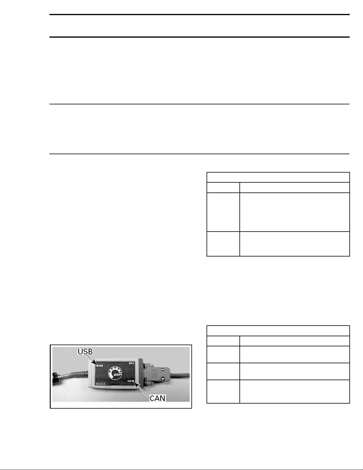
STATUS BAR
1. Number of modules read by B.U.D.S.
lmr2010-019-001
MODULE SUBMENU - LIST OF MODULES READ BY B.U.D.S.
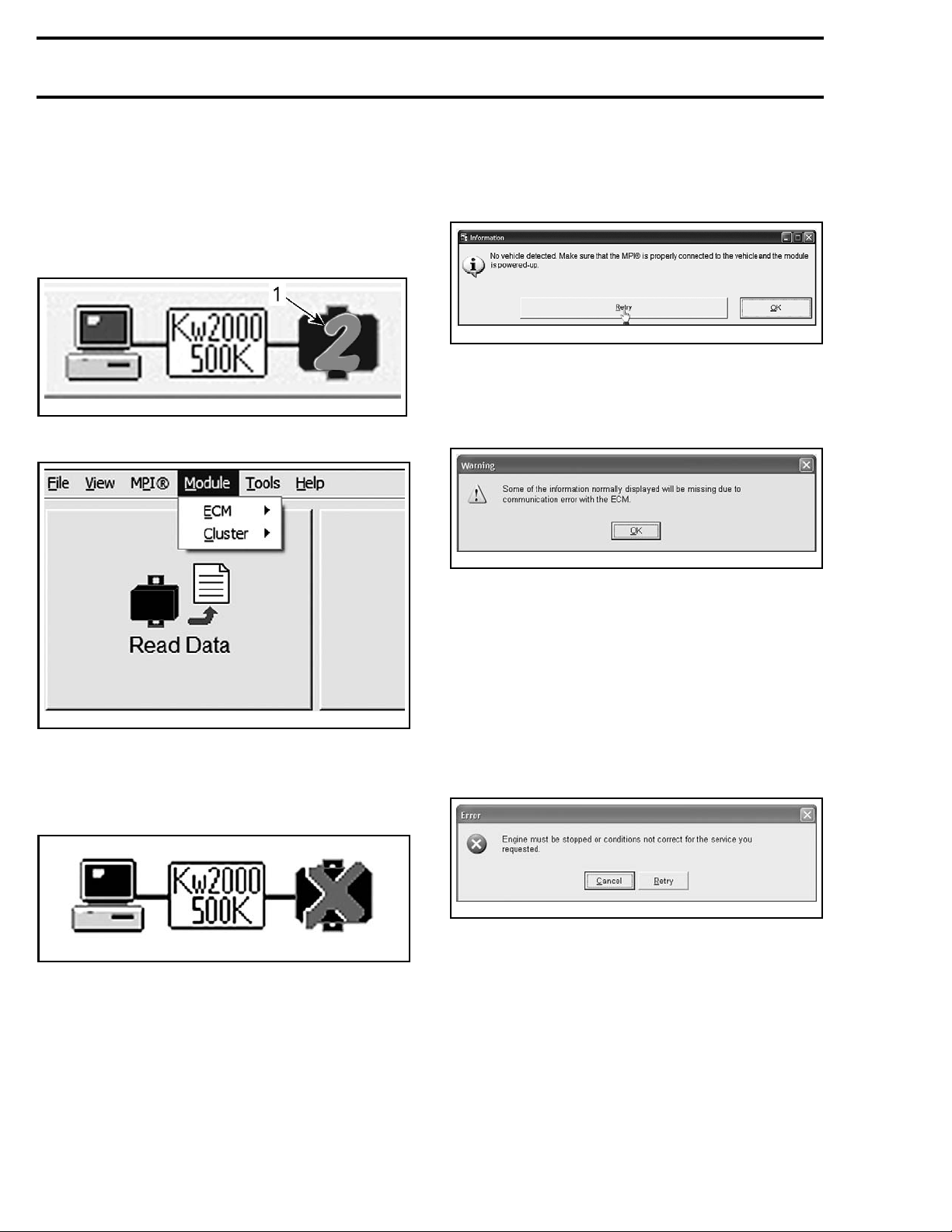
No Vehicle Detected
If an “X” is shown in the status bar, it means that
no ECU is communicating with the MPI.
rmr2010-020-009
1. Check connections between the PC computer
and the vehicle.
2. Ensure the electrical system is powered up.
NOTE: The tether cord cap must be installed on
the engine cut-off switch.
3. Ensure both USB and CAN lights on the MPI-2
are GREEN. Refer to
MPI-2 CONNECTION
TROUBLESHOOTING
subsection.
If B.U.D.S. does not automatically exit the follow-
ing message box, click the Retry button. This will
manually establish the communication with the
ECUs.
smr2014-026-003_a
Message Box: "Some of the Information
Normally Displayed..."
If the following message box is displayed in
B.U.D.S.:
smr2009-028-016
1. Click on the OK button in the box.
2. Ensure the tether cord is properly installed.
3. Briefly press the vehicle START button to acti-
vate the ECM. Do not hold START button to
avoid engine starting.
4. Click on the Read Data button in B.U.D.S.
Message Box: "Engine must be Stopped..."
If the following message box is displayed in
B.U.D.S.:
smr2009-028-015
1. Turn off the engine if it is running.
2. Click ontheCancel button in B.U.D.S.
3. Ensure the tether cord is properly installed.
4. Briefly press the vehicle START button to acti-
vate the ECM. Do not hold START button to
avoid engine starting.
5. Continue with the procedure undertaken prior
to the appearance of the message box.
NOTE: If the message persists and the engine is
not running, press the Read Data button. There-
after, repeat the procedure.
2smr2014-026