Standalone operation
4
a. Administrator enrolment
The steady blue LED means that the BioLock is waiting to enrol (or
register) the fingerprint of the administrator (who can then control
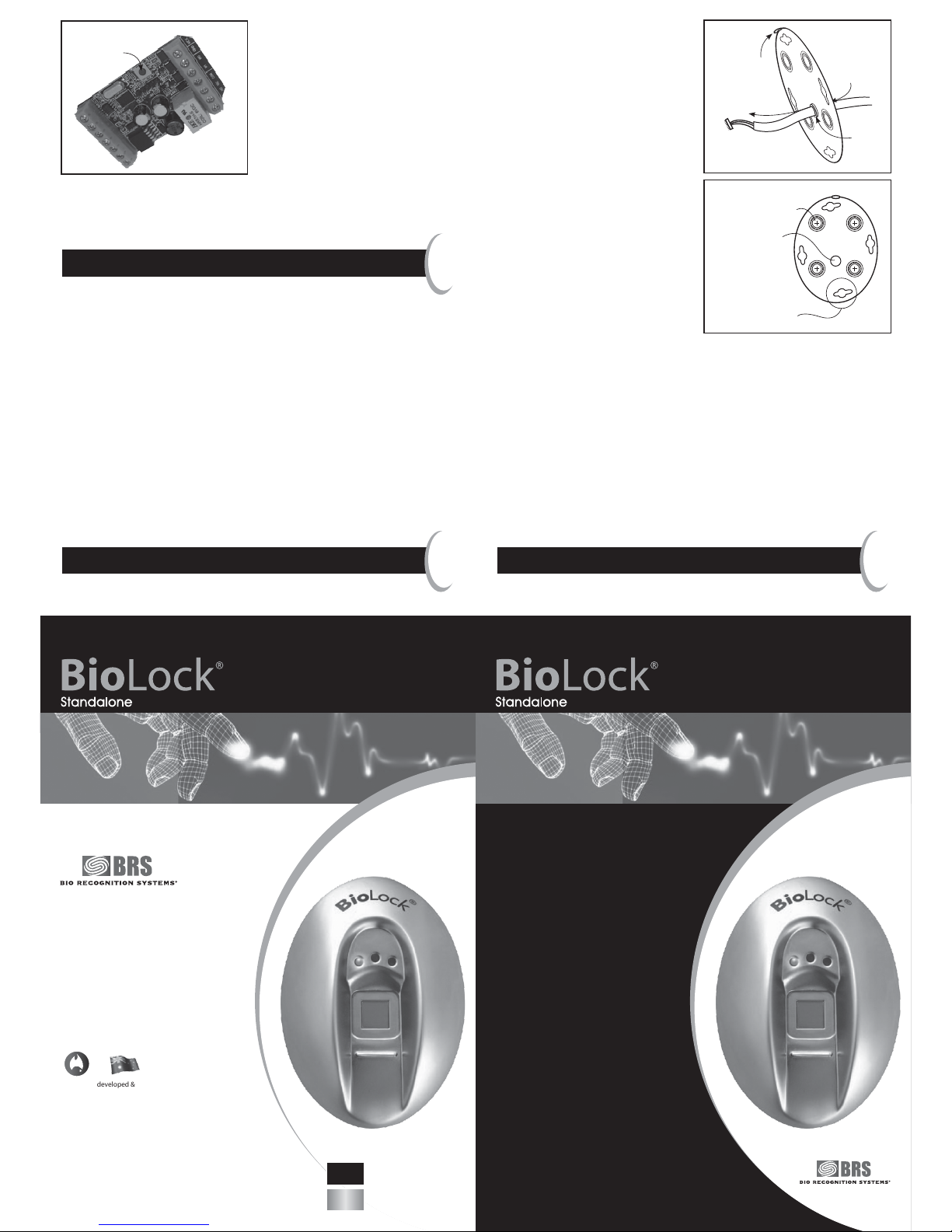
access through the door). Correctly placing your finger is critical.
Find the crease at the first knuckle joint of your finger or thumb.
Place it on the locating ridge of the BioLock, below the square sensor.
Keeping your finger straight and the knuckle joint crease on the
locating ridge, lift your wrist to tilt your finger firmly onto the surface
of the sensor (see diagram 3 below) until the blue LED goes out. Do
not move or rotate your finger while it is on the sensor.
Lift your finger off the sensor and repeat the finger press several
times, until the green LED turns on to indicate a high-quality
enrolment. A minimum of five presses and a maximum of twenty is
required. After each press, a high-pitch beep indicates the quality is
increasing, and low-pitch beep indicates no increase in quality.
Check the enrolment by placing your enrolled finger or thumb again.
The green LED should light and the door strike should release for three
seconds and the door can be opened.
If a high-quality enrolment is not achieved, firstly try again with a
different finger. Avoid very moist and very dry fingers, and pressing
too lightly or too heavily. In extreme cases, log into the web logs (see
Advanced Settings) and monitor the enrolment quality (a score of 50
is required for success).
The BioLock in its resting state will flash the blue LED briefly every
three seconds.
b. Enrolling a user
To add a user, the administrator should verify their finger twice in
quick succession. The blue LED will flash for two seconds with audio
beeping, then turn a solid blue.
Instruct the user to place their finger or thumb in exactly the
same manner as for the administrator enrolment until a green
LED enrolment acknowledgement is achieved. The number of beeps
indicates the user number enrolled (and the sequence is repeated
twice). Check the enrolment by another user finger press and ensure
the door strike activates.
If the user number was missed, it can be checked at any time by
the administrator verifying their finger, followed straight away
by a user verification.
Users can also be enrolled with the assistance of the web pages
(see Advanced Settings).
c. Deleting a user
To delete a user, the administrator should verify their finger three
times in quick succession. The red LED will flash for two seconds with
audio beeping, then turn a solid red.
If the user is present, they should place their finger again. If
recognised, the green LED will turn on and beep to indicate success.
Try another verification to check the user can no longer gain access
through the door.
If the user is not present, tap the sensor (rather than hold down your
finger for a verification) the number of times corresponding to the
user number. If you miscount your taps, just keep tapping longer than
the total number of fingers enrolled to abort.
Users can also be deleted via the web pages (see Advanced Settings).
d. PIN entry
A PIN number can (optionally) be set to allow access without having
a fingerprint enrolled. To add or modify the optional bypass PIN, the
administrator should verify their finger four times in quick succession.
The green LED will flash for two seconds with audio beeping, then turn
a solid green.
Add or modify the 4-digit bypass PIN by then tapping the sensor the
desired PIN code, pausing after each digit until the green LED flashes
in acknowledgement. The PIN may also be set via the web pages (see
Advanced Settings).
To use the PIN (once entered), simply tap the sensor with the
PIN code, pausing after each digit until the green LED flashes in
acknowledgement. After the 4th digit (if correct) the door strike
will activate.
To cancel the bypass PIN, the administrator should enter PIN mode
but not enter any taps, letting the unit time-out.
e. Deleting all users
To delete all users, the administrator should verify their finger five
times in quick succession. All the LEDs will flash for a second with
audio beeping. During this beeping/flashing, the administrator should
verify a sixth time to confirm the deletion.
All user fingerprint records will be permanently deleted and the blue
LED will remain on, waiting for an Administrator enrolment.
Troubleshooting
5
If no LEDs light on the BioLock, check the cabling against the wiring
diagram supplied. Check that at least one LED on the SIOB turns on.
If not, then a power or wiring problem is likely.
In normal standalone mode, the blue BioLock LED will flash briefly
every three seconds and on the SIOB a green LED flashes.
If instead the Blue BioLock LED is flashing every half-second, the
BioLock is not communicating properly with the SIOB. Often this
will be related to a problem with the wiring between the two devices.
Also, the SIOB and BioLock are “paired” when they first communicate
with each other. If this “pairing” is lost (for instance, if an SIOB or
BioLock is changed), the SIOB needs to be “factory reset”.
To factory-reset the SIOB, briefly press the reset switch on the SIOB
with the power on.
If you have difficulty communicating with the BioLock via the
Ethernet port (either with the Windows™ BioLock application
program, or with logging into the BioLock via a web browser), test
the connection with the “ping” command described in the Advanced
Settings below. Problems with Ethernet communications are usually
cabling problems, software firewall settings, or network settings of
the PC. If you have a network hub or switch, some types are known to
have trouble auto-detecting Ethernet speeds (BioLock runs at 10MHz)
and may need to be manually set. If you are connecting directly
to the BioLock with a PC or laptop that is not capable of
auto-switching, you will need a crossover Ethernet cable.
Check for IP address conflicts by disconnecting the BioLock
and performing a “ping” of the BioLock static IP address to
see if another device is using it. Also check that any DHCP servers
do not allocate IP addresses dynamically in a range that includes
the BioLock IP address.
If the BioLock IP address has been lost or forgotten, you may be
able to recognise it by typing the “arp –a” at a DOS prompt. If
you cannot proceed further, the default BioLock settings including
the IP address can be restored by means of a factory reset of the
BioLock. This also
removes all stored user information (such as
enrolled fingers and logs).
To factory-reset the BioLock, turn the power off then on. When the
green LED extinguishes and during the LEDs cycle sequence, tap the
SIOB sensor four times to reset. Note that in this case, all the BioLock
internal configurations are reset, including the IP address, and may
need to be changed via the web page (see the Advanced Settings).
If the BioLock is factory-reset, the SIOB will also need to be factory-
reset. To do this, momentarily press the reset button on the SIOB.
Advanced settings
6
The BioLock has a built-in web server, with a lot of
available information.
Connect the BioLock up to a PC, by plugging in an Ethernet LAN
cable into the RJ45 socket on the BioLock cable. Note that if you are
connecting the BioLock directly to a PC or laptop that is not capable
of auto-switching, a crossover Ethernet cable must be used.
Note: to initially log into the BioLock, your PC must be on the
same local subnet as the BioLock, i.e. 192.168.0.xxx. To find out your
current IP address, click Start > Run… and in the dialogue box type
“cmd” and enter. In the DOS box that is created, type “ipconfig” to
see if your PC has a similar address. If not, make note of your current
IP address, subnet, gateway address, DHCP settings of your PC’s
network adapter that will be used to connect to the BioLock – you
may need to return the PC settings back once you have finished.
To allow connectivity to the BioLock, change your PC’s IP address
to any address in the range 192.168.0.1 – 192.168.0.255 excluding
192.168.0.210 which is the default BioLock address. To do this, click
Start > Settings > Network and dialup connections, click on the
network adapter used, then Properties > Internet Protocol (TCP/IP)
> Properties. Seek expert assistance if you are not confident of your
knowledge. Once the PC’s IP address is in the correct range, in a DOS
box type “ping 192.168.0.210” to ensure the BioLock is responding
(with something similar to “Reply from 192.168.0.210: bytes=32
time=xx ms TTL=128”).
In any web browser (e.g. Internet Explorer™), type in the address bar
http://192.168.0.210 and log in with the default username “admin”
and password “password”.
The web pages are largely self-explanatory; however note that the
time/date should be set correctly (or NTP settings correct to pick up
the time setting via the Internet) for logged events to have the correct
time/date. Users can be labelled with their names for easier log
interpretation. The default username and password should be changed
to prevent unauthorised changes or access.
If multiple BioLocks are to run on a network, they should have
unique IP addresses (the IP address will need to be changed from the
default). If you need to, change the BioLock IP address to a spare IP
address on your network.
Note that the troubleshooting web page can control the LEDs, test
the buzzer and fire the SIOB relay/door strike. This may be useful for
accessing the BioLock remotely via the Internet and remotely allowing
one-time access.
The BioLock may be used in standalone-only mode (no network
control), or PC-software control via Bio Recognition Systems’ BioLock
Windows™ software application (available either in your kit or
downloaded online from www.brsgrp.com/biolock/biolock.exe), or in
dual-mode: Windows-software mode if available and communicating
with the BioLock, or standalone mode if not. Note that user
enrolments are not transferred automatically between the Windows
and standalone modes.
BioLock Windows™ software
7
BioLocks may be run completely standalone, however for some
applications Bio Recognition Systems’ BioLock Windows software may
allow additional useful functions. Examples:
• Multiple doors or other devices controlled by multiple BioLocks,
with only a single enrolment for users
• Time-zone access control, allowing you to grant access only on
specific days or times of the week
• Customisable access logs, able to be exported to other applications
in a flexible format
Install the BioLock software from the included CD-ROM, or download
from www.brsgrp.com/biolock/biolock.exe and follow the installation
instructions included. Once installed, follow the on-line help to
initialise BioLocks and add and enrol users.
To add a BioLock unit in the software, click on “Units” then right-click
on “Config”. Enter the appropriate fields, click “Apply” then “Test
Unit” to confirm it is on-line. To add a user, click on “Users”, then
right-click on Configure Users”, “Add User” and complete the details.
Then enrol a finger by right-clicking on the user, “Add Template” and
follow the sequence of actions suggested.
BioLocks may be solely standalone, solely Windows™ controlled, or
both (if the Windows™ BioLock application is on-line, then under
Windows™ control, otherwise in standalone or fallback mode).
The mode setting is done via the BioLock configuration web page. A
BioLock on-line in Windows™ mode will have the green LED flashing;
in standalone mode will have the blue LED flashing.
Outer Sensor Array,
Stainless Steel
approx 3mm wide
Diagram 3
Locating ridge in
finger crease
Finger
Internal
Sensor Array