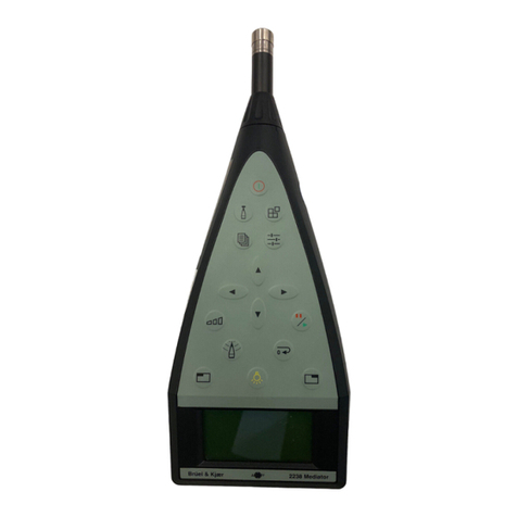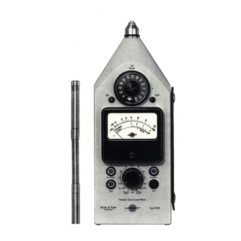
Sound Level Meter Type 2237A+B
Service Manual Brüel & Kjær
0−4
Power Supply Board ZD 0393 ................................................................................ 4–2
Battery Voltage and Current................................................................................. 4 – 3
Back-up Battery ..................................................................................................... 4 – 3
Input Stage ............................................................................................................. 4 – 4
No supply to the Digital Board.............................................................................. 4 – 4
The Display............................................................................................................. 4 – 4
Battery Low ............................................................................................................ 4 – 4
4.3 Adjustment Procedure ................................................................................................ 4 – 4
ZD 0814 Digital Board Reference Voltage............................................................. 4 – 7
ZZ 0233 Analogue Board ........................................................................................ 4 – 7
RMS Detector Gain and Offset.............................................................................. 4 – 7
Peak Detector Gain and Offset.............................................................................. 4 – 8
5. Mechanical Parts.......................................................................................................... 5 – 1
5.1 Exploded View............................................................................................................. 5 – 2
5.2 Dismantling Kit WZ 0065 ........................................................................................... 5 – 3
5.3 Dismantling................................................................................................................. 5 – 3
5.4 Reassembly.................................................................................................................. 5 – 4
5.5 Service Parts List........................................................................................................ 5 – 5
6. Theory of Operation................................................................................................... 6 – 1
6.1 Introduction................................................................................................................. 6 – 2
6.2 Functional Description ............................................................................................... 6 – 2
Signal Flow ............................................................................................................. 6 – 2
Internal Control...................................................................................................... 6 – 2
Interfaces ................................................................................................................ 6 – 3
Power Supply.......................................................................................................... 6 – 3
6.3 Block Diagram............................................................................................................. 6 – 4
A. Appendix – Type 2237 B ........................................................................................ A–1
A.1 Introduction................................................................................................................ A – 2
A.2 Upgrade ...................................................................................................................... A – 2
A.3 Special Tools and Equipment .................................................................................... A – 2
A.4 Repair.......................................................................................................................... A – 2
A.5 Field Replaceable Parts ............................................................................................. A – 2
A.6 Preparation................................................................................................................. A – 3
A.7 Checking Procedure ................................................................................................... A – 4
Initial Checks ........................................................................................................ A – 4
A.8 Initial setting.............................................................................................................. A – 4
A.9 Checking Outputs ...................................................................................................... A – 4
AC output............................................................................................................... A – 4
Digital output ........................................................................................................ A – 4
A.10 Frequency Weighting................................................................................................. A – 5
