Brunner Anliker FAM 16 User manual

Operating Manual
Fruit Declumper
FAM 16
Translation of the German Original

Generated:
Reviewed:
Revised:
Status: 300 released
Page 2 of 26
Ralph Moretti
Michel Benkovics
Document number:
Index
12 Feb 2018
BA

Generated:
Reviewed:
Revised:
Status: 300 released
Page 3 of 26
Ralph Moretti
Michel Benkovics
Document number:
Index
12 Feb 2018
BA
SAFETY GUIDELINES
This operating manual provides information which the operator of the device needs to observe in order
to ensure personal safety and to prevent damage to property. All safety issues are pointed out by
warning triangles and classified according to their degree of risk:
DANGER!
Death, severe bodily injury or considerable damage to property will
occur if the
respective precautions are not taken.
WARNING!
Death, severe bodily injury or considerable damage to property may
occur if the
respective precautions are not taken.
CAUTION!
Minor bodily injury or damage to property may occur
if the respective precautions
are not taken.
NOTE!
Important information on the product, on handling procedures or on a specific
part of the documentation you should pay particular attention to.
Qualified
personnel
The FAM16 fruit declumper
may be commissioned and operated by qualified
personnel only. A person is deemed qualified in regard to the safety regulations
contained in this operating manual if he or she has received training and
instructions on the system.
Please note: The
manufacturer cannot be held liable for accidents or damages caused by the
non-
observance of the safety instructions, by inadequate procedures or by
inappropriate use.
WARNING!
The FAM16 fruit declumper may only be used for the applications described in the
specifications and technical description and with the spare parts recommended by
Brunner-Anliker AG.
Smooth and safe operation of the product depends on its professional and correct
transport, storage, in
stallation and assembly as well as on its proper and careful
handling and maintenance.

Generated:
Reviewed:
Revised:
Status: 300 released
Page 4 of 26
Ralph Moretti
Michel Benkovics
Document number:
Index
12 Feb 2018
BA
Copyright © Brunner-Anliker AG 2018 All rights reserved
Any reproduction, transmission or use of this document or its
contents is not permitted without our explicit written consent.
We shall claim damages in case of violations of the above. All
rights reserved.
Brunner-Anliker AG
8302 Kloten
Switzerland
Disclaimer
We reviewed the contents of this publication to ensure compliance
with the described FAM16 fruit declumper. As differences cannot,
however, be completely excluded, we cannot guarantee absolute
compliance. The information provided in this publication is reviewed
at regular intervals and the changes are included in the subsequent
issue.
We welcome any suggestions for improvements.
© Brunner-Anliker AG-2018

Generated:
Reviewed:
Revised:
Status: 300 released
Page 5 of 26
Ralph Moretti
Michel Benkovics
Document number:
Index
12 Feb 2018
BA
PREAMBLE / IMPORTANT INFORMATION
Purpose of this
operating manual
This operating manual is meant to support the specialist in familiarizing with and
handling the FAM16 fruit declumper.
Readers
This operating manual is intended for all those installing, operating and maintaining
the FAM16 fruit declumper made by Brunner-Anliker AG.
Notification
obligation
The operating manual and applicable regulations must be kept in a place accessible to
the operating and maintenance personnel
NOTE!
In addition to the operating manual, all those handling the IR 250 must observe and be
instructed on the generally applicable and mandatory regulations relevant to accident
prevention.
Scope of
application of this
operating manual
This operating manual applies to the FAM16 fruit declumper.
NOTE!
Functional modifications to the FAM16 fruit declumper
annul all liability and warranty
claims.
Obligations of the
operating
company
The operator is obligated to operate the FAM16 fruit declumper
in flawless condition
only. Hazard spots between the FAM16 fruit declumper and customer equipment must
be secured by the operator.
Please read this operating manual carefully and completely. Contact us immediately in
case of uncertainties. Do not operate
the device before all uncertainties have been
clarified. By commissioning the equipment,
you confirm that you have read and
understood the operating manual contents.
HAZARD!
Accidents may occur if the FAM16 fruit declumper
is not used as intended or in
improper or defective condition.

Generated:
Reviewed:
Revised:
Status: 300 released
Page 6 of 26
Ralph Moretti
Michel Benkovics
Document number:
Index
12 Feb 2018
BA
Table of contents
1Introduction........................................................................................................................... 8
2Intended use.......................................................................................................................... 8
2.1 Limitation of liability.......................................................................................................... 8
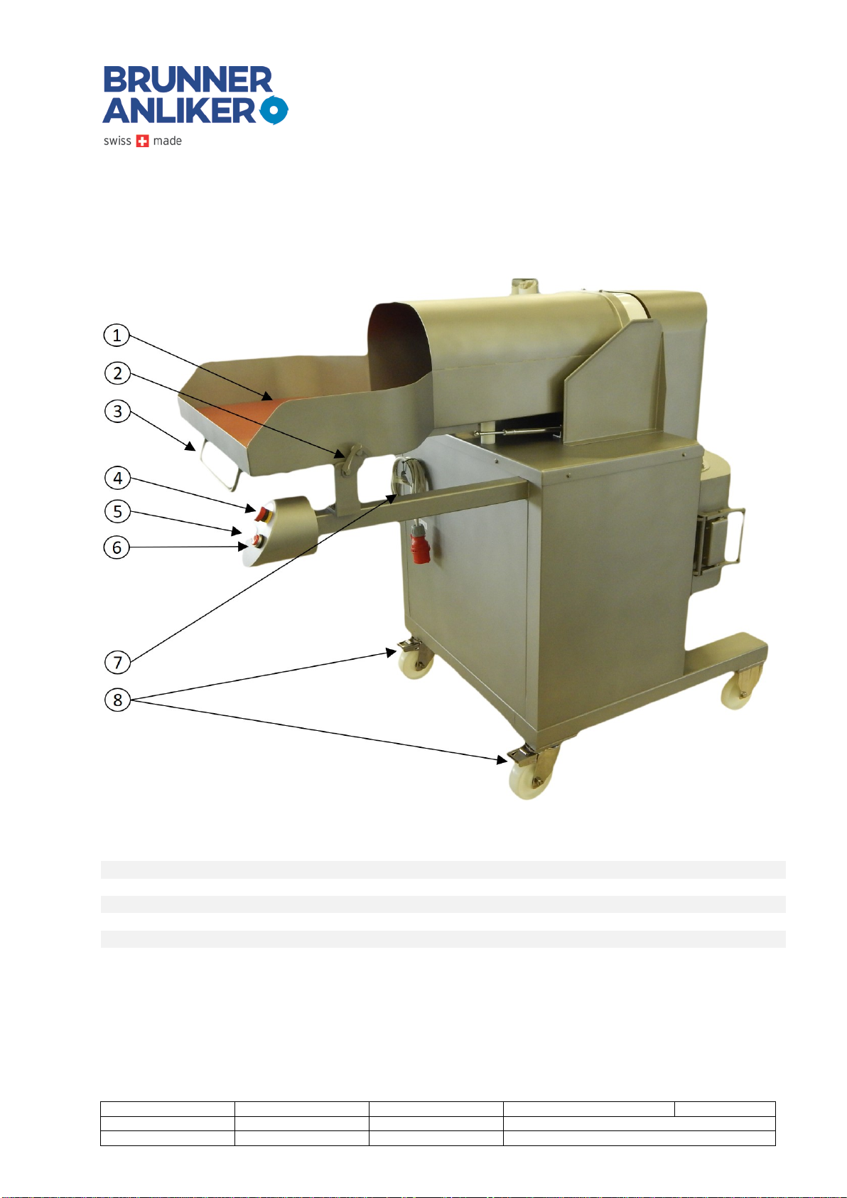
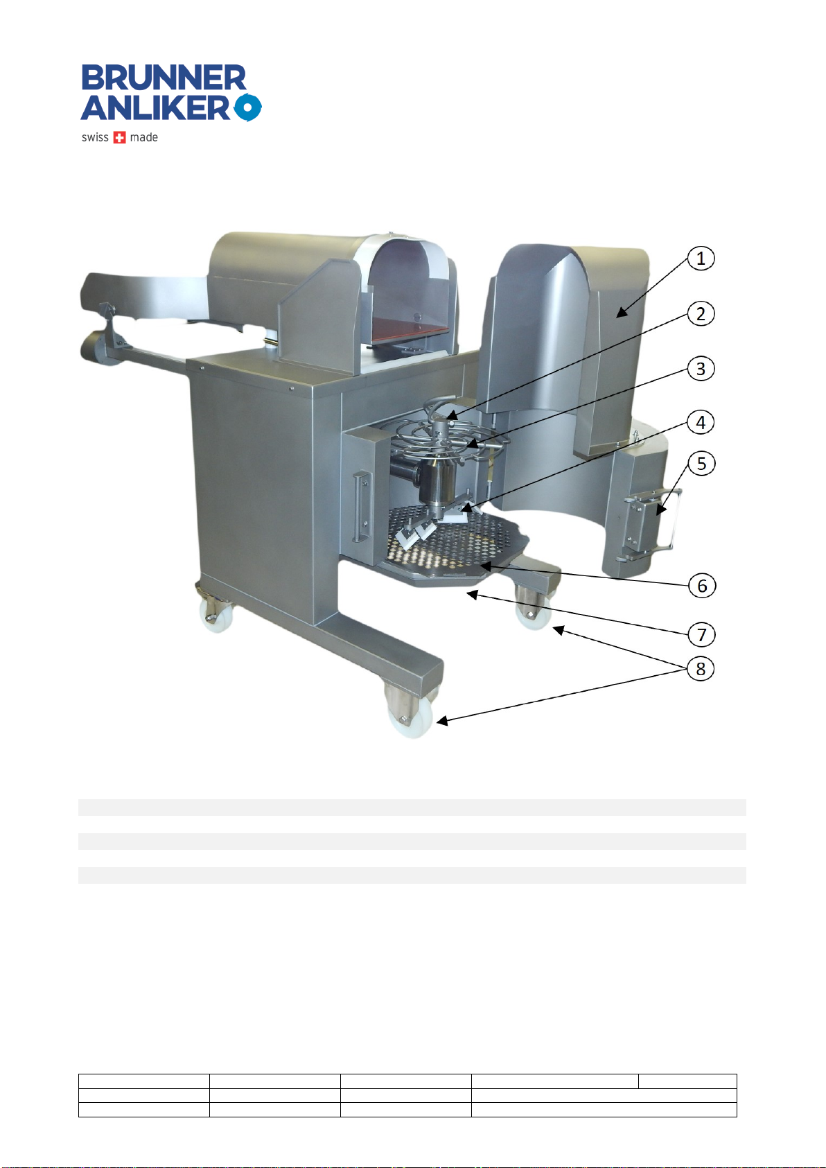
3System components ............................................................................................................... 9
3.1 Front view (operator side).................................................................................................. 9
3.2 Rear view ....................................................................................................................... 10
4Scope of supply .................................................................................................................... 11
4.1 Scope of supply............................................................................................................... 11
4.2 Accessories .................................................................................................................... 12
5Transport and installation instructions ................................................................................... 13
5.1 Consignment .................................................................................................................. 13
5.2 Start-up ......................................................................................................................... 13
6Operation ............................................................................................................................ 14
6.1 Preparing the machine .................................................................................................... 14
6.2 Fruit processing .............................................................................................................. 18
7System maintenance............................................................................................................. 19
7.1 Cleaning......................................................................................................................... 19
8Troubleshooting ................................................................................................................... 21
8.1 Delivered fruit too big - fruit not completely declumped...................................................... 21
8.2 Delivered fruit too small - fruit crushed or cut. ................................................................... 21
8.3 Obstruction - nothing goes in, nothing goes out.................................................................. 21
8.4 Service line..................................................................................................................... 22
9Spare parts .......................................................................................................................... 22
9.1 Disposal ......................................................................................................................... 22
10 Transfer to third parties ...................................................................................................... 22
11 Technical specifications....................................................................................................... 23
11.1 Dimensional drawing....................................................................................................... 24
12 CE Conformity Declaration................................................................................................... 25
13 Warranty ........................................................................................................................... 26

Generated:
Reviewed:
Revised:
Status: 300 released
Page 7 of 26
Ralph Moretti
Michel Benkovics
Document number:
Index
12 Feb 2018
BA
List of illustrations
Fig. 1: Rear view ...........................................................................................................................9
Fig. 2: Rear view .........................................................................................................................10
Fig. 3: Pre-separator hook Fig. 4: Spiral separator Fig. 5: Scraper unit 11
Fig. 6: 6-mm Allen® key ...............................................................................................................11
Fig. 7: Perforated plate variant Fig. 8: Spiral separator variant..........................12
Fig. 9: Locking the caster brake.....................................................................................................13
Fig. 10: Observe the rotation direction!.........................................................................................13
Fig. 11: Opening the hood Fig. 12: Hood open ...........................................................................14
Fig. 13: Installing the scraper unit .................................................................................................14
Fig. 14: Inserting the perforated plate ...........................................................................................15
Fig. 15: Mounting the spiral separator Fig. 16: Spiral separator mounted ................................15
Fig. 17: Mounting the pre-separator hook Fig. 18: Pre-separator hook mounted .....................15
Fig. 19: Adjusting / removing the scrapers Fig. 20: Adjusting the scrapers ..............................16
Fig. 21: Scraper arrangement .......................................................................................................16
Fig. 22: Scraper...........................................................................................................................17
Fig. 23: Twin spiral separator mounted on the bottom ....................................................................17
Fig. 24: Lifting the slide................................................................................................................18
Fig. 25: Locking the chute ............................................................................................................19
Fig. 26: Lifting the plastic plate .....................................................................................................19
Fig. 27: Scraper unit across the plate ...........................................................................................20
Fig. 28: Inserting the plate ..........................................................................................................20
Fig. 29: Perforated plate edges....................................................................................................21
Fig. 27: Dimensional drawing........................................................................................................24
Fig. 28: CE conformity declaration.................................................................................................25
List of tables
Table 1 Operator side 9
Table 2 Rear 10
Table 3 Technical specifications 23

Generated:
Reviewed:
Revised:
Status: 300 released
Page 8 of 26
Ralph Moretti
Michel Benkovics
Document number:
Index
12 Feb 2018
BA
1Introduction
Thank you very much for your trust in us and our products.
The machines made by Brunner-Anliker AG are of high quality. The quality assurance measures in place
at Brunner-Anliker AG ensure that all machines leave the plant in perfect condition. By purchasing the
FAM16 fruit declumper made by Brunner-Anliker AG, you have decided in favor of a sophisticated, state-
of-the-art product.
2Intended use
The FAM16 is the perfect tool for declumping pressed blocks of dried fruit or frozen vegetables into
friable and undamaged single products.
Maximum processable block size = 300 x 300 x 200 mm
NOTE!
•The device may only be used for the products approved by the manufacturer.
•Any other use is considered improper and contrary to that originally intended.
HAZARD!
•The manufacturer cannot be held liable for accidents or damages caused by the non-
observance of the safety instructions, by inadequate procedures or by inappropriate
use of the machine.
2.1 Limitation of liability
NOTE!
The operator of the machine is responsible for the compliance of the entire system with
the local regulations regarding the installation and operation of such systems.
After assembly and installation of the machine, it is the operator's duty to verify the safety
of the system. The operator must also ensure that exposed system parts which could pose
a hazard to the operating personnel are screened or equipped with appropriate safety
devices.

Generated:
Reviewed:
Revised:
Status: 300 released
Page 9 of 26
Ralph Moretti
Michel Benkovics
Document number:
Index
12 Feb 2018
BA
3System components
3.1 Front view (operator side)
Fig. 1: Rear view
Table 1 Operator side
Item
Item
1 Chute
5 ON switch
2 Chute lock
6 OFF switch
3 Lift handle
7 Cable holder with power cable
4 EMERGENCY OFF switch
8 Swivel casters with brakes

Generated:
Reviewed:
Revised:
Status: 300 released
Page 10 of 26
Ralph Moretti
Michel Benkovics
Document number:
Index
12 Feb 2018
BA
3.2 Rear view
Fig. 2: Rear view
Table 2 Rear
Item
Item
1 Declumper hood
5 Lock
2 Pre-separator hook
6 Perforated plate
3 Spiral separator
7 Outlet
4 Scraper unit
8 Rigid casters

Generated:
Reviewed:
Revised:
Status: 300 released
Page 11 of 26
Ralph Moretti
Michel Benkovics
Document number:
Index
12 Feb 2018
BA
4Scope of supply
4.1 Scope of supply
The FAM16 consignment consists of the machine itself, the operating manual, pre-separator hook, spiral
separator, scraper unit, 19-mm socket wrench and 6-mm Allen® key.
Fig. 3: Pre-separator hook Fig. 4: Spiral separator Fig. 5: Scraper unit
Fig. 6: 6-mm Allen® key

Generated:
Reviewed:
Revised:
Status: 300 released
Page 12 of 26
Ralph Moretti
Michel Benkovics
Document number:
Index
12 Feb 2018
BA
4.2 Accessories
The FAM16 fruit declumper can be equipped with a variety of perforated plates
to suit all types of fruit (e.g. dried fruit).
Fig. 7: Perforated plate variant Fig. 8: Spiral separator variant

Generated:
Reviewed:
Revised:
Status: 300 released
Page 13 of 26
Ralph Moretti
Michel Benkovics
Document number:
Index
12 Feb 2018
BA
5Transport and installation instructions
5.1 Consignment
5.2 Start-up
The mobile machine must be placed on an even surface (do not use on sloping surfaces).
Leave enough space around the machine for the provision and infeed of fruit blocks as well as
for the container catching the singulated products. The space should allow unobstructed lifting
of the chute and opening of the declumper hood.
The machine must be locked in place with the caster brakes: Push the brake down with your
foot until they snap into place.
Fig. 9: Locking the caster brake
Connect the cable to high-current power supply (400V).
Check the direction of rotation of the motor: the pre-separator hook must rotate in the indicated
direction (counterclockwise)!
Fig. 10: Observe the rotation direction!

Generated:
Reviewed:
Revised:
Status: 300 released
Page 14 of 26
Ralph Moretti
Michel Benkovics
Document number:
Index
12 Feb 2018
BA
6Operation
6.1 Preparing the machine
The machine must be prepared for the fruit to be processed. Ensure that the machine is switched OFF.
Open the declumper hood: pull the handle and swing the hood to the side.
Fig. 11: Opening the hood Fig. 12: Hood open
Mount the scraper unit. Insert from below, push up and onto the drive shaft. The scrapers must face
down. The bayonet lock lobes must snap into place. Tighten the hexagonal head screw with the key of
the accessories kit to lock the scraper unit securely on the shaft.
Fig. 13: Installing the scraper unit

Generated:
Reviewed:
Revised:
Status: 300 released
Page 15 of 26
Ralph Moretti
Michel Benkovics
Document number:
Index
12 Feb 2018
BA
Insert the perforated plate into its frame. Ensure that the right side faces up. The hole size should
comply with that of the declumped fruit pieces.
Fig. 14: Inserting the perforated plate
Place the spiral separator on the upper end of the drive shaft. The bayonet lock lobes must snap into
place.
Fig. 15: Mounting the spiral separator Fig. 16:
Spiral separator mounted
Mount the pre-separator hook on the drive shaft. The bayonet lock lobes must snap into place. Tighten
the hexagonal head screw with the key of the accessories kit to lock the pre-separator hook securely on
the shaft.
Fig. 17: Mounting the pre-separator hook Fig. 18: Pre-separator hook mounted

Generated:
Reviewed:
Revised:
Status: 300 released
Page 16 of 26
Ralph Moretti
Michel Benkovics
Document number:
Index
12 Feb 2018
BA
Adjust the distance and orientation of the four scrapers on the scraper unit. The distance between
scrapers and perforated plate should roughly comply with the size of the singulated fruit pieces. The
spiral separator indicates the direction of rotation which needs to be observed for scraper adjustment.
The stud screws can be loosened and tightened with the key in the accessories kit.
Fig. 19: Adjusting / removing the scrapers Fig. 20: Adjusting the scrapers
Fig. 21: Scraper arrangement

Generated:
Reviewed:
Revised:
Status: 300 released
Page 17 of 26
Ralph Moretti
Michel Benkovics
Document number:
Index
12 Feb 2018
BA
NOTE!
•Ensure that all screws on the scrapers sit tight and that the scrapers do not rub
against the wall!
Fig. 22: Scraper
Instead of the scraper unit and the perforated plate, a second spiral separator can be mounted on the
bottom of the machine. Please see our information on the tool configuration required for each type of
fruit.
Fig. 23: Twin spiral separator mounted on the bottom
Close the declumper hood. Please note that for safety reasons the drive cannot be started before the
hood is closed and secured.

Generated:
Reviewed:
Revised:
Status: 300 released
Page 18 of 26
Ralph Moretti
Michel Benkovics
Document number:
Index
12 Feb 2018
BA
6.2 Fruit processing
1. Start the machine.
2. Place a container suitable for collection of the singulated fruit products under the declumper.
3. Unpack the products (fruit) for declumping.
4. Remove the packaging material (e.g. plastic bag).
5. Lift the chute with the handle and slide the block into the machine.
Fig. 24: Lifting the chute
NOTE!
•Plastic bags or other packaging material must not get into the machine.

Generated:
Reviewed:
Revised:
Status: 300 released
Page 19 of 26
Ralph Moretti
Michel Benkovics
Document number:
Index
12 Feb 2018
BA
7System maintenance
7.1 Cleaning
Switch the machine off and unplug the power cable.
To remove the plastic plate for cleaning, block the loading device with the hook to prevent it from
springing back.
Fig. 25: Locking the chute
Lift the plastic plate through the oval openings from below, pull out from above.
Fig. 26: Lifting the plastic plate
Open and swing out the declumper hood.
Loosen but do not remove the hexagon head screw on the pre-separator hook.
Rotate the pre-separator hook counterclockwise out of the bayonet lock and pull it off the drive shaft.
Rotate the spiral separator counterclockwise out of the bayonet lock and pull it off from above.
Lift the perforated plate and pull it out of its frame.

Generated:
Reviewed:
Revised:
Status: 300 released
Page 20 of 26
Ralph Moretti
Michel Benkovics
Document number:
Index
12 Feb 2018
BA
In case of narrow distances to the scrapers, rotate the scraper unit until it is positioned transversely to
the machine rotation direction. Very small distances may require raising of the scrapers to allow
removal of the perforated plate.
Fig. 27: Scraper unit placed transversely to the plate
After removal of the perforated plate, loosen the hexagon head screw on the scraper unit. Rotate
counterclockwise out of the bayonet lock and pull it off the drive shaft from below.
NOTE!
-For storage and cleaning, the loading unit must be blocked with the hook.
Insertion of the plastic plate: ensure that the plate is inserted correctly. The side with the angled corner
must be placed on the hinge side of the hood.
Fig. 28: Inserting the plate
Table of contents
Other Brunner Anliker Commercial Food Equipment manuals
Popular Commercial Food Equipment manuals by other brands

Omcan
Omcan Aurora PT-CN-0686E-HC instruction manual

ROBAND
ROBAND 40DT instruction manual

purecold
purecold INSPIRATION2 Installation, operation & maintenance manual

SandenVendo
SandenVendo HFD000006 Technical & service manual

Tecfrigo
Tecfrigo OASI 4 M Installation and use

OEM
OEM FX201-M Operating and service manual

Diamond
Diamond RVE/3C-SBC manual

Giorik
Giorik HI LITE Installation, Operation and Maintenace Manual

MKN
MKN Combisteamer Silver II Troubleshooting

Delfield
Delfield 18600 Series Installation, operation and maintenance manual

Bravetti
Bravetti PLATINUM PRO KP400H owner's manual

etol
etol Blu'line Blu'box 52 GN user manual