Brusa NLG664-U0 Manual

TECHNICAL INFORMATION
AND START-UP
Translation of the original German operating instructions
On-board Fast Charger
NLG664-U0
BRUSA Elektronik AG
Neudorf 14
CH-9466 Sennwald
+41 81 758 19 00
www.brusa.biz inf[email protected]

Technical information
and start-up
Fast Charger NLG6xx
2
LEGAL NOTICE
Publisher
BRUSA Elektronik AG
Neudorf 14
CH–9466 Sennwald
T +41 81 758 19 - 00
F +41 81 758 19 - 99
www.brusa.biz
office@brusa.biz
Date of issue
07.10.2016
Copyright
© 2016
The content of this document may not be passed on to third parties without the written authorisation
of the company BRUSA Elektronik AG –
not even in extracts. Any technical information, drawings
and photos used are copyrighted and failure to respect this constitutes a punishable offence!
Updates
In light of the further technical development of our products, we reserve
the right to make
constructional changes. Any changes will be made known in the relevant manuals through the
replacement of the relevant pages and/or a revision of the electronic data storage device.
Originator / author
Holger Schmidt / Manuel Tschumper / Beat Graf
REVISIONS
Revision Date Name Change
01
---
HS
Translation of rev01 german - no changes
02
01.02.2013
HS
Chapter 6.1, 7.1.4.2, 7.1.4.7 and 7.3.1 corrected
03
07.02.2013
HS
Chapter 7.1.5 - Pin 6+8 WakeUp - functions changed
04
25.03.2013
HS
Chapter 6.3 corrected, minor corrections
05
14.10.2013
MT
Chapter 3.3.3 / 6.6 / 9.1 tightness note LV cabel
06
18.11.2013
MT
Chapter. 1.1 VDE
07
17.12.2013
MT
200 V - 450 V
08
12.02.2015
bg
General Revision
09
09.11.2015
bg
Chapter 5.1 Vehicle integration / EMC
10
21.11.2016
bg
Upgrade 50/60Hz, 1-ph/7kW, max. 50mA WakeUp current
11 28.11.2016 ag Chapter 11 Warranty new; Chapter 12 Instructions regarding
disposal new

Technical information
and start-up
Fast Charger NLG6xx
3
VALIDITY
This manual is only valid for those devices listed in the following table:
NLG664 – U0 – xxA – xxx *
* x = applies for all models
The decoding of the device designation is as follows:

Technical information
and start-up
Fast Charger NLG6xx
4
TABLE OF CONTENTS
1
Foreword.................................................................................................................................. 7
1.1
General characteristics...................................................................................................................7
1.2
Labelling information, traceability and documentation of devices and components.......................... 8
2
List of abbreviations................................................................................................................ 8
3
Safety and warning instructions ............................................................................................ 9
3.1
Symbols and their meaning............................................................................................................9
3.2
Safety instructions and danger levels ...........................................................................................10
3.3
Generally applicable safety measures..........................................................................................11
3.4
Safety installations / power limitations.......................................................................................... 14
3.4.1 Control Pilot acc. to SAEJ1772 and / or IEC61851................................................................ 14
3.4.2 Mains overvoltage protection.................................................................................................14
3.4.3 Mains protection input current ...............................................................................................14
3.4.4 Overcurrent protection...........................................................................................................14
3.4.5 Overtemperature protection (derating)...................................................................................15
3.4.6 HV Interlock acc. to LV123....................................................................................................16
3.4.7 Proximity Detection acc. to IEC 61851 ..................................................................................17
3.4.8 Active discharge....................................................................................................................17
3.5
Requirements on the start-up personnel.......................................................................................18
4
General................................................................................................................................... 19
4.1
Content and scope of this manual ................................................................................................19
4.2
Scope of the documentation.........................................................................................................19
4.3
Scope of delivery..........................................................................................................................19
4.4
Optional scope of delivery ............................................................................................................20
4.5
Applicable standards....................................................................................................................20
4.6
Contact information of the manufacturer.......................................................................................20
5
Use and limitations of the product....................................................................................... 21
5.1
Proper use....................................................................................................................................21
5.2
Improper Use / Limitations of the product.....................................................................................21

Technical information
and start-up
Fast Charger NLG6xx
5
6
About this device................................................................................................................... 23
6.1
Technical data..............................................................................................................................23
6.2
Warnings on the device................................................................................................................25
6.3
Technical properties.....................................................................................................................26
6.4
Basic function...............................................................................................................................26
6.4.1 Voltage-dependent control of 1-phase and 3-phase charging................................................ 27
6.4.2 PFC compensation................................................................................................................27
6.4.3 PRC compensation ...............................................................................................................27
6.5
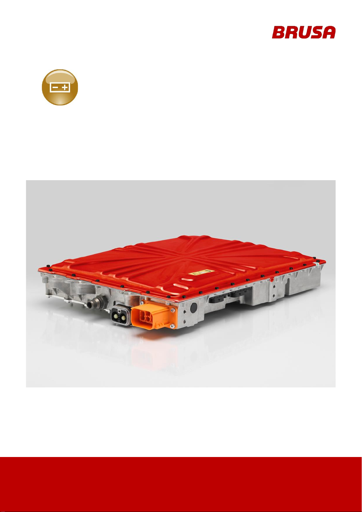
Overview of the main structural components................................................................................ 28
6.6
Dimensions and installation information .......................................................................................29
6.6.1 Fixing points..........................................................................................................................30
6.6.2 Dimensions ...........................................................................................................................31
6.6.3 Installation position................................................................................................................31
6.7
Vehicle installation basic principle................................................................................................32
6.8
Block diagram ..............................................................................................................................33
6.9
Type plate ....................................................................................................................................34
7
Connections........................................................................................................................... 35
7.1
Electrical ......................................................................................................................................35
7.1.1 Earthing / Grounding Screw (equipotential bonding)..............................................................36
7.1.2 Pin assignment DC plug (Code A, device side) .....................................................................37
7.1.3 Pin assignment AC mains plug (Code A, device side)........................................................... 38
7.1.4 Pin assignment LV plug vehicle 12-pole (Code A, device side).............................................. 39
7.1.5 Pin assignment LV plug charging socket 12-pole (Code B, device side)................................ 44
7.2
Cooling water connections ...........................................................................................................48
7.3
Wakeup mechanism.....................................................................................................................49
7.3.1 WakeUp via CAN ..................................................................................................................49
7.3.2 WakeUp via Proximity...........................................................................................................50
7.3.3 WakeUp via Pin HW-WakeUp...............................................................................................50
7.3.4 WakeUp via Control Pilot CP................................................................................................. 50
7.3.5 WakeUp via AC (mains voltage)............................................................................................50
7.4
Power limitations / Limiting controller............................................................................................51
7.4.1 Input current limitation Indem................................................................................................51
7.4.2 Input power limitation Pndem................................................................................................52
7.4.3 Mains voltage dependent limitation .......................................................................................52

Technical information
and start-up
Fast Charger NLG6xx
6
7.4.4 Proximity Detection ...............................................................................................................52
7.4.5 Control Pilot...........................................................................................................................52
7.4.6 Temperature derating............................................................................................................52
7.4.7 Output current limitation Iadem ............................................................................................. 52
7.4.8 Output voltage limitation Uadem............................................................................................52
8
Efficiency ............................................................................................................................... 53
8.1.1 Level of efficiency 1-phase charging .....................................................................................53
8.1.2 Level of efficiency 3-phase charging .....................................................................................53
9
Installation / Start-up............................................................................................................. 54
9.1
Installation and connection of charger..........................................................................................54
9.2
Removing the charger..................................................................................................................58
9.3
Precharge output capacitor ..........................................................................................................62
10
Operation ............................................................................................................................... 63
11
Warranty and Guarantee....................................................................................................... 63
12
Instructions regarding disposal........................................................................................... 63
13
Index....................................................................................................................................... 64

Technical information
and start-up
Fast Charger NLG6xx
7
1
Foreword
Dear Customer!
With the BRUSA NLG6 charger, you have purchased a versatile high-performance product. The device is a
power electronics product which uses dangerous voltages and currents, thus special expertise with respect
to handling and operation of such systems is required!
Read this manual – particularly the chapter Safety and warning instructions – carefully before you install the
Fast Charger NLG6xx or carry out any other work on it!
1.1
General characteristics
INFORMATION
Below there is a short overview of the performance and versatility of the NLG6 charger.
You will find details on the individual properties as you read through thismanual.
Manufactured and tested according to European automotivestandards.
This VDE-certified charger complies with all applicable European legal requirements. EMC
compliance is to be achieved in combination with the vehicle.
Galvanic isolation between mains and battery circuit guarantees optimum protection ofpersonnel.
Touch and leakage current values remain within required limits, without further measures.
The charger can be used in connection with a standard type A RCD.
The power factor cos(phi) is nearly =1, therefore the available mains power is used to themaximum.
The charging current contains a very low ripple.
Charging from single or three-phase outlet.
Parallel connection of several chargers is possible, in order to achieve higher chargingpower.
Highly efficient (typically >94%).
Robust against dust, humidity, vibration etc.

Technical information
and start-up
Fast Charger NLG6xx
8
1.2
Labelling information, traceability and documentation of devices and components
BRUSA Elektronik AG ensures a complete quality proof for all raw materials, manufacturing
processesand products by means of suitable labelling and traceabilitymeasures.
Traceability shall be organised in such a way that in the event of a defect the following characteristics
can be identified at any time:
Manufacturer
Production batch
Production line
Original batch
2
List of abbreviations
Throughout this manual, certain specific technical abbreviations are used. The following table provides an
overview of these abbreviations and their meaning:
Abk. Bezeichnung Abk. Bezeichnung
BMS
Battery
Μ
anagementSystem
LV
Low Voltage
BTL
cycle
Time quanta per Bit NBT
NLG
Netzladegerät (AC charger)
CAN
Controller Area Network
PFC
Power Factor Correction
CP
Contol Pilot
PI
Power Indicator
EME
Electromagnetic Emission
PLC
PowerLine Communication
EMI
Electromagnetic Interference
PRC
Power Ripple Compensation
EVSE
Electric Vehicle Supply Equipment
PWM
Pulse-Width Modulation
GND
Ground
RTC
Real Time Clock
HV
High Voltage (hazardous voltage)
SAE
Society of Automotive Engineers
IEC
International Electrotechnical Commission
SJW
Synchronization Jump Width
LED
Light Emitting Diode
VCU
Vehicle Control Unit

Technical information
and start-up
Fast Charger NLG6xx
9
3
Safety and warning instructions
In this chapter, you will find safety instructions applying to this device. These instructions refer to the
assembly, start-up and the running operation in the vehicle. Always read and observe these instructions in
order to protect people's safety and lives and to avoid damage to the device!
3.1
Symbols and their meaning
Throughout this manual, certain specific symbols are used. The following table provides an overview of
these abbreviations and their meaning:
Symbol Meaning Symbol Meaning
General prohibition
Warning! High voltage!
Do not touch
Do not switch
Symbol
Meaning
Symbol
Meaning
General warning of a dangerous area
Warning! Electrical shock!
Warning! Explosive environment!
Warning! Danger caused by batteries!
Warning! Hot surface!
Warning! High voltage!
Warning! High pressure / fluid ejection!
Warning! Fire hazard!
Symbol Meaning Symbol Meaning
Disconnect device from power supply
Disconnect device from mains
Symbol Meaning Symbol Meaning
Important information on avoiding possible
property damage
Important information

Technical information
and start-up
Fast Charger NLG6xx
10
3.2
Safety instructions and danger levels
DANGER
This instruction warns about severe irreversible risks of personal injury with possibly fatal
consequences.
Avoid this risk by adhering to these instructions!
CAUTION
This instruction warns about a minor risk of injury!
Avoid this risk by adhering to these instructions!
INSTRUCTION
This instruction warns against possible damages to property if the following instructions and work
procedures are not observed.
INFORMATION
This type of instruction makes important information known to the reader.
WARNING
This instruction warns about the risk of severe but reversible injury!
Avoid this risk by adhering to these instructions!

Technical information
and start-up
Fast Charger NLG6xx
11
3.3
Generally applicable safety measures
The following safety measures have been developed based on the knowledge of the manufacturer. They are
incomplete as they can be supplemented by local and/or country-specific safety instructions and guidelines
for accident prevention.
The system integrator and/or distributor of the device must therefore supplement the present general safety
instructions with country-specific and local guidelines.
3.3.1 Safety instructions for cooling water systems
WARNING
Cooling fluid ejection!
Danger of burns!
Check the water tightness of the cooling water system, particularly the pipes, screw jointsand
pressure tanks!
Repair any identifiable leaksimmediately!
Ensure at all times that the maximum permissible pressure in the cooling system is notexceeded
(e.g. by installation of pressure compensation valves)!
Ensure at all times that the maximum permissible cooling water temperature is notexceeded!
3.3.2 Safety instructions for mechanical systems
DANGER
Explosive environment!
Danger to life!
Do not store any highly flammable substances or combustible fluids in the direct surroundingsof
the device! Sparks forming at the device's connections can set these on fire and lead to
explosions!
CAUTION
Hot surfaces!
Burn hazard!
The device produces high temperatures when in operation! Therefore, the device is tobe
handled with care and caution at all times!

Technical information
and start-up
Fast Charger NLG6xx
12
3.3.3 Safety instructions for handling and operation
INSTRUCTION
Damage to HV battery:
Make sure that the voltage range of the device complies with the voltage range of the HVbattery!
Only use technically suitable and high-quality cables! Should you have any further questions,
please contact BRUSA Elektronik AG under the manufacturer address mentioned in chapter4.6.
INSTRUCTION
Damage to the charger:
When connecting the device, always ensure that the mains voltage is within thepermissible
range (refer to chapter 6.1 Technicaldata)!
A high cooling water temperature and/or ambient temperature reduces the life span!Therefore,
ensure that the device is continuously cooledsufficiently!
Do not install the device in direct sunlight and in direct proximity to heatsources!
Even though the device has a high IP protection class, direct contact with water (rain,splashing
water) and dirt should be avoided.
Under no circumstances should you put a low-resistance connection between the HV contacts,
the housing contacts and the LV contacts! This will lead to malfunctions and in time to the
destruction of the device!
Prevent any penetration of fluids into the device (e.g. during assembly work)! Fluid ingresswill
lead to a short circuit and subsequently to damage to thedevice!
In the case of any fluid ingression, do not start the device and immediately contactBRUSA
Elektronik AG.
The tightness of the battery charger can only be guaranteed if all the signal cable to the signal
connectors are packaged and connected to a tight unit. If this is not the case in one of the cables,
it must be separately sealed.

Technical information
and start-up
Fast Charger NLG6xx
13
3.3.4 Safety instructions for electrical systems
DANGER
High voltage!
Danger to life!
Never touch the HV wires or HV connections without ensuring the absence ofvoltage
beforehand!
The device may only be connected by a qualified electrician! Refer to chapter 3.5Requirements
on the start-up personnel
Safety installations must never be by-passed or circumvented! Any resulting malfunctionscould
have life threatening consequences!
Never connect the device to a socket without a protective earthconductor!
Always apply a residual current device (RCD) to the mainsconnection!
CAUTION
Damage to the cable!
Fire hazard!
If a cable drum is used as an extension cord to the mains connection, it might ignite due toheat
accumulation! Therefore, always unwind the cable drumcompletely!
INSTRUCTION
The device is never to be opened! The opening of the device (sealed housing) directly leads to the
forfeiture of any liability by BRUSA Elektronik AG! Refer to chapter 11 Liability
INFORMATION
When working on a HV system, the following 5 safety rules have to be strictly adhered to:
Disconnect system from power.
Switch off the ignition.
Remove service / maintenance plug and/or turn off main battery switch
Remove fuse
Ensure that the system cannot be reactivated.
Keep ignition key safe to prevent unauthorised access.
Keep the service / maintenance plug safe in order to prevent unauthorised access and/or
use lockable cover cap to ensure that the main battery switch is not reactivated.
Ensure that the device is de-energised by using a suitable voltage tester (pay attention tothe
voltage range!)
Earth and short-circuit the system.
Cover or isolate adjacent live parts.

Technical information
and start-up
Fast Charger NLG6xx
14
3.4
Safety installations / power limitations
3.4.1 Control Pilot acc. to SAEJ1772 and / or IEC61851
Control-Pilot (CP) is a standardised signal transmitted via an additional conductor in the charging plug. The
CP interface enables a bidirectional exchange of information between the charging station and electric
vehicle and is globally standardised. Thanks to this signal, the EVSE can provide the charger with
information on the permissible maximum current load of the mains socket and the available power capacity.
In case of the NLG6, this current can be max 32 A (= max. current limited by the charger). The charging
process is coordinated via this signal and appropriate grounding is ensured.
The Control Pilot is a safety measure that also increases the reliability of the charging process of an electric
vehicle. It is absolutely necessary if the charging current on the mains side exceeds 16A.
3.4.2 Mains overvoltage protection
Overvoltage protection is integrated in the charger to provide permanent protection against overloading.
Mains overvoltage is detected by the quick sensor system and leads to immediate shut down of the charger.
Highly energetic overvoltage (e.g. due to lightning) is absorbed by protective elements.
Also on the output side, overvoltage protection is integrated. The quick sensor system detects overvoltage
on the HV battery side (e.g. load drop or fluctuations) and the charger is immediately shut down.
3.4.3 Mains protection input current
On the charger, each phase (L1, L2, L3, N) is protected by a 40 A fuse in order to protect the device and
electric systems from damage due to overcurrent. If one of these fuses is blown, the charger must be
returned to BRUSA Elektronik AG! Do not open the device – no user serviceable parts inside.
3.4.4 Overcurrent protection
Overcurrent protection is integrated in the charger to avoid overload damage. The quick sensor system
detects any overcurrent and either reduces the current by regulation or shuts the charger down.
INSTRUCTION
We strongly recommended that you install a suitable overcurrent protection (fuse) close to the battery
between charger and battery, in order to protect the wires between charger and battery!

Technical information
and start-up
Fast Charger NLG6xx
15
3.4.5 Overtemperature protection (derating)
INSTRUCTION
Continuous operation at the temperature limit will inevitably lead to a higher level of wear of the
components!
The charger protects itself through temperature dependent derating. If the charger reaches a defined
temperature limit, it reduces the power (derating) to protect the charger from damage due to overheating.
The power is reduced according to the temperature increase in order to keep the temperature within the
target range. The charging process is not interrupted though, but continues seamlessly without reduced
power. If the temperature of the coolant exceeds +65 °C, we recommend to shut down the charger to
prevent damage. We recommend not to exceed a maximum coolant temperature of +55 °C.
In total, the NLG6 charger is equipped with 10 temperature sensors in different areas. Depending on the
operation situation, activation time and temperature of the derating may thus vary.

Technical information
and start-up
Fast Charger NLG6xx
16
3.4.6 HV Interlock acc. to LV123
The interlock is a protective loop in the vehicle which monitors the drive components. It also allows
monitoring of HV side plug connections at the charger. Wiring of the interlock pins does not influence the
functionality of the charger, but in order to ensure safety, we strongly recommend that an interlock system is
employed! These interlock pins can carry +/-48VDC nominal to Gnd, at 10mA (max. 20mA).

Technical information
and start-up
Fast Charger NLG6xx
17
3.4.7 Proximity Detection acc. to IEC 61851
Proximity defines an additional resistor attached to the connector of the charging cord, which indicates the
maximum ampacity of the cord. This resistor is measured by the charger and defines the amount of current
that the cord is allowed to conduct. This resistor is standardised and therefore independent of the
manufacturer. Due to Proximity Detection the charger can detect:
Whether a charging cable is connected to thevehicle
Which cable type is connected
Which amperage is possible with the charging cable (range of 6 -
63 A) The NLG6 charger generally limits the possible charging current
to max. 32A.
INFORMATION
For this function, a 4.7 kΩ resistor must be integrated in the Charge Coupler! This must be provided
by the customer (refer to drawing).
3.4.8 Active discharge
The device features active discharge of circuits. As soon as the device is disconnected from the HV, the
internal HV circuits discharge:
at applied HV voltage 320 V = < 2.4 s to < 30 V
at applied HV voltage 420 V = < 4.7 s to < 30 V

Technical information
and start-up
Fast Charger NLG6xx
18
3.5
Requirements on the start-up personnel
All courses of action described in this manual may only be carried out by a qualified electrician! Specialist
staff are defined as electricians who have had
specific professional training,
have knowledge and experience in the field of electronics / electricmobility,
as well as knowledge of relevant provisions and dangers
for which they can provide proof. Furthermore, they must be able to assess the work assigned to them
independently, identify possible dangers and establish necessary protection measures.

Technical information
and start-up
Fast Charger NLG6xx
19
4
General
4.1
Content and scope of this manual
The present documentation gives an overview of all required working steps regarding the installation and
operation of the charger and the necessary safety measures.
It contains technical data, application information and a basic description of the charger and its functions.
The operational and safety instructions provided are to be adhered to in order to ensure personal safety as
well the ongoing optimum functioning of the charger. This is also a precondition to meet warranty
requirements of BRUSA Elektronik AG.
4.2
Scope of the documentation
INFORMATION
In order to successfully commission the charger, you need this manual and the software manual, and
possibly further software. BRUSA will be happy to provide this so-called (documentation-
) “customer
package” by download links.
4.3
Scope of delivery
Meaning Pieces Illustration
1.
Mains charger NLG664
1

Technical information
and start-up
Fast Charger NLG6xx
20
4.4
Optional scope of delivery
INFORMATION
These accessories can be obtained optionally from BRUSA Elektronik AG.
Meaning Type Illustration
1.
NLG6 CEQ 4-part cable set, assembled on one side
13198
---
2.
Quick connection cooling water ports 90° Norma PS3
(required inner diameter of cooling water tube = 18 mm)
MHAA776
3.
Quick connection cooling water ports 0° Norma PS3
(required inner diameter of cooling water tube = 18 mm)
MHAA775
4.5
Applicable standards
The NLG6 charger is designed according to IEC61851 (mains side) and LV123 (HV DCside).
The NLG6 charger is exclusively approved for Europe.
The NLG6 charger is CE compliant. EMC radiation must be evaluated and tested in the complete
system, since mounting and wiring have a large influence on radiationbehaviour.
This manual has been produced under application and consideration of the EC guidelines, national
laws and harmonised standards (EN) valid at the time of production relevant to the Fast Charger
NLG6xx.
4.6
Contact information of the manufacturer
BRUSA Elektronik AG
Neudorf 14
9466 Sennwald
Switzerland
Phone:
+41 81 758 19 – 00
Fax:
+41 81 758 19 – 99
Internet:
www.brusa.biz
E-mail:
support@brusa.biz
Table of contents
Other Brusa Batteries Charger manuals