—4—
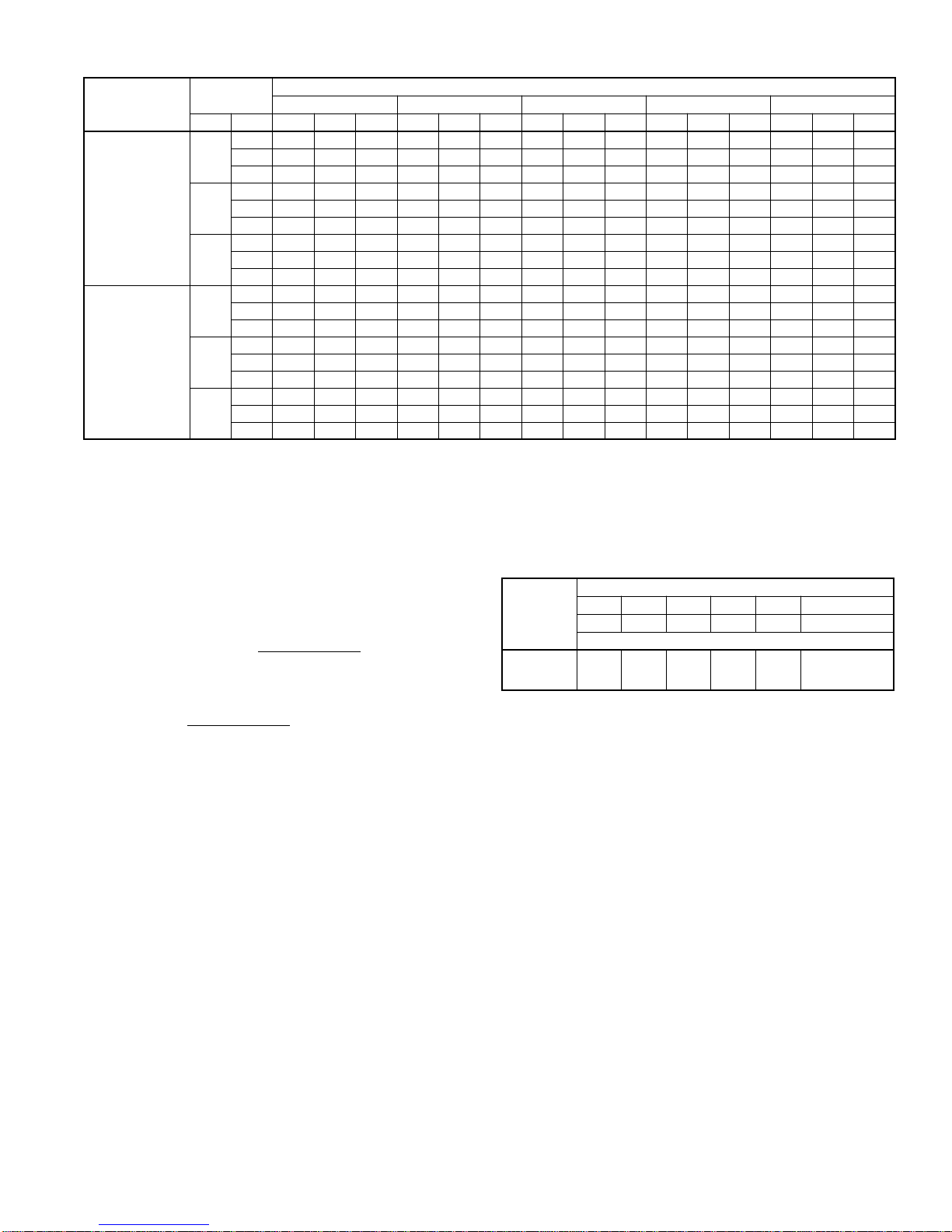
GROSS COOLING CAPACITIES (MBH)
CFM
— Cubic Ft per Minute
EWB
— Entering Wet Bulb (°F)
TC
— Gross Cooling Capacity 1000 Btuh
SHC
— Gross Sensible Capacity 1000 Btuh
BF
— Bypass Factor
MBH
— 1000 Btuh
UNIT
SIZE
INDOOR COIL
AIR SATURATED TEMPERATURE LEAVING EVAPORATOR (°F)
30 35 40 45 50
CFM EWB TC SHC BF TC SHC BF TC SHC BF TC SHC BF TC SHC BF
A018
450 72 31.9 14.8 0.00 28.9 13.4 0.00 26.0 12.1 0.00 22.6 10.7 0.07 18.5 9.04 0.06
67
26.8 15.8 0.07 23.7 14.3 0.06 20.5 12.8 0.05 16.7 11.2 0.04 12.5 9.40 0.05
62
21.8 16.6 0.04 18.6 14.9 0.04 15.4 13.3 0.05 12.3 11.7 0.08 9.95 9.95 0.18
600 72 37.5 17.3 0.00 34.0 15.8 0.00 30.5 14.2 0.16 26.5 12.6 0.11 22.1 10.9 0.09
67
31.3 18.7 0.10 27.8 17.1 0.09 24.3 15.5 0.08 20.1 13.7 0.07 15.2 11.7 0.09
62
25.8 20.1 0.08 22.2 18.4 0.08 18.6 16.6 0.08 15.2 14.7 0.11 12.5 12.5 0.22
750 72 41.7 19.2 0.00 37.9 17.6 0.00 34.0 16.0 0.17 29.6 14.2 0.14 24.7 12.4 0.12
67
35.1 21.2 0.13 31.0 19.5 0.12 26.9 17.7 0.11 22.6 15.9 0.11 17.4 13.7 0.12
62
28.4 22.9 0.10 24.9 21.3 0.10 21.4 19.6 0.11 17.7 17.5 0.14 14.8 14.8 0.26
A024
W024
600 72 38.7 17.9 0.00 35.4 16.4 0.00 32.0 15.0 0.13 28.1 13.3 0.08 23.7 11.6 0.07
67
32.6 19.5 0.07 29.1 17.9 0.06 25.6 16.3 0.06 21.5 14.5 0.05 16.6 12.5 0.06
62
27.0 20.9 0.05 23.4 19.2 0.05 19.8 17.4 0.05 16.2 15.5 0.08 13.3 13.3 0.18
800 72 44.0 20.4 0.21 40.4 18.9 0.17 36.8 17.3 0.13 32.4 15.6 0.11 27.2 13.7 0.10
67
37.4 22.8 0.10 33.5 21.1 0.10 29.5 19.4 0.09 25.0 17.5 0.08 19.7 15.4 0.09
62
30.6 25.0 0.07 27.0 23.2 0.08 23.4 21.4 0.09 19.7 19.3 0.12 16.6 16.6 0.23
1000 72 47.9 22.3 0.18 44.0 20.7 0.17 40.1 19.2 0.16 35.5 17.4 0.14 30.0 15.4 0.13
67
40.7 25.5 0.13 36.6 23.8 0.13 32.4 22.0 0.12 27.3 20.0 0.11 21.9 17.9 0.12
62
33.7 28.6 0.10 30.0 26.7 0.11 26.2 24.9 0.12 22.7 22.5 0.17 19.4 19.4 0.28
A030
W030
750 72 54.4 25.3 0.00 48.7 22.7 0.00 43.1 20.1 0.00 36.6 17.3 0.07 29.3 14.5 0.06
67
45.1 26.5 0.07 39.1 23.7 0.07 33.2 20.9 0.06 26.7 18.1 0.05 20.0 15.2 0.08
62
36.0 27.3 0.05 30.5 24.5 0.06 25.0 21.8 0.07 19.7 19.0 0.09 16.1 16.1 0.21
1000 72 64.1 29.5 0.00 57.7 26.7 0.00 51.2 23.9 0.19 43.9 20.9 0.12 35.2 17.6 0.10
67
53.6 31.8 0.11 46.8 28.7 0.10 40.1 25.6 0.10 32.3 22.3 0.09 24.1 18.8 0.11
62
43.4 33.4 0.10 36.9 30.3 0.10 30.4 27.2 0.10 24.3 24.0 0.12 20.1 20.1 0.26
1250 72 72.1 33.0 0.00 64.7 29.9 0.00 57.3 26.8 0.20 49.4 23.7 0.15 40.1 20.3 0.14
67
59.6 35.8 0.14 52.4 32.7 0.14 45.3 29.5 0.13 36.8 25.9 0.13 27.5 22.0 0.15
62
49.0 38.4 0.14 42.0 35.2 0.13 35.0 32.1 0.13 28.6 28.4 0.16 23.7 23.7 0.30
A036
N036
T036
W036
900 72 63.4 29.6 0.00 57.2 26.8 0.00 50.9 23.9 0.00 44.3 21.0 0.00 36.3 17.9 0.00
67
52.1 31.0 0.00 46.0 28.1 0.00 39.8 25.1 0.00 32.8 22.1 0.00 24.9 18.8 0.01
62
42.8 32.7 0.00 36.7 29.6 0.00 30.5 26.6 0.01 23.9 23.0 0.04 19.2 19.2 0.18
1200 72 75.1 34.7 0.00 67.8 31.6 0.00 60.5 28.5 0.05 52.1 25.1 0.03 43.4 21.8 0.02
67
61.6 37.2 0.02 54.5 34.0 0.02 47.5 30.8 0.02 39.3 27.3 0.02 30.2 23.4 0.04
62
51.1 40.2 0.02 44.0 36.7 0.03 36.9 33.2 0.03 29.3 28.9 0.08 24.2 24.2 0.22
1500 72 83.3 38.5 0.17 75.5 35.3 0.13 67.6 32.1 0.09 58.5 28.5 0.06 48.4 24.8 0.06
67
69.4 42.5 0.06 61.3 38.9 0.06 53.1 35.4 0.05 44.4 31.7 0.05 34.5 27.5 0.07
62
56.6 46.2 0.04 49.3 42.5 0.06 42.0 38.8 0.07 34.3 34.3 0.11 28.8 28.8 0.25
A042
N042
T042
1050 72 75.4 35.0 0.00 68.0 31.8 0.00 60.7 28.6 0.02 52.7 25.3 0.00 43.6 21.7 0.00
67
62.1 37.3 0.00 55.0 34.0 0.00 47.8 30.7 0.00 39.3 26.9 0.01 30.2 23.1 0.03
62
51.5 39.8 0.01 44.2 36.2 0.01 36.9 32.7 0.02 29.1 28.3 0.06 23.7 23.7 0.20
1400 72 87.8 40.6 0.18 79.4 37.1 0.13 71.0 33.6 0.07 61.3 29.8 0.05 51.0 25.9 0.05
67
72.9 44.4 0.05 64.4 40.7 0.04 55.9 36.9 0.04 46.7 33.0 0.04 36.1 28.5 0.06
62
60.0 48.3 0.03 52.0 44.3 0.05 44.0 40.3 0.06 35.5 35.5 0.10 29.7 29.7 0.24
1750 72 96.3 44.6 0.16 87.4 41.1 0.13 78.5 37.5 0.11 67.9 33.5 0.09 55.9 29.1 0.09
67
80.8 50.1 0.08 71.5 46.1 0.08 62.2 42.2 0.08 51.9 37.9 0.08 40.9 33.4 0.10
62
65.7 55.1 0.07 57.6 50.9 0.08 49.5 46.6 0.10 41.7 41.7 0.15 35.0 35.0 0.28
A048
N048
T048
W048
1200 72 79.8 36.9 0.00 72.6 33.7 0.00 65.4 30.6 0.12 57.0 27.1 0.08 47.5 23.4 0.07
67
66.6 39.8 0.07 59.1 36.4 0.06 51.7 33.0 0.06 43.2 29.3 0.05 33.3 25.2 0.07
62
55.2 42.8 0.06 47.6 39.1 0.06 40.0 35.4 0.06 32.2 31.3 0.08 26.7 26.7 0.20
1600 72 91.0 42.1 0.22 83.0 38.7 0.18 75.0 35.4 0.13 65.4 31.7 0.11 54.5 27.6 0.10
67
76.7 46.9 0.10 68.1 43.1 0.10 59.5 39.4 0.09 50.1 35.4 0.09 39.4 31.0 0.11
62
62.7 51.0 0.08 54.9 47.2 0.09 47.1 43.4 0.10 39.3 39.0 0.13 33.1 33.1 0.25
2000 72 99.2 46.1 0.19 90.7 42.7 0.17 82.2 39.4 0.15 72.0 35.5 0.14 60.0 31.2 0.13
67
84.0 52.6 0.13 74.8 48.8 0.13 65.7 44.9 0.12 55.1 40.5 0.12 44.0 36.0 0.13
62
69.0 58.5 0.11 60.8 54.3 0.12 52.6 50.2 0.14 45.4 45.4 0.18 38.5 38.5 0.30