Installation Instructions
NOTE: Read the entire instruction manual before starting the
installation.
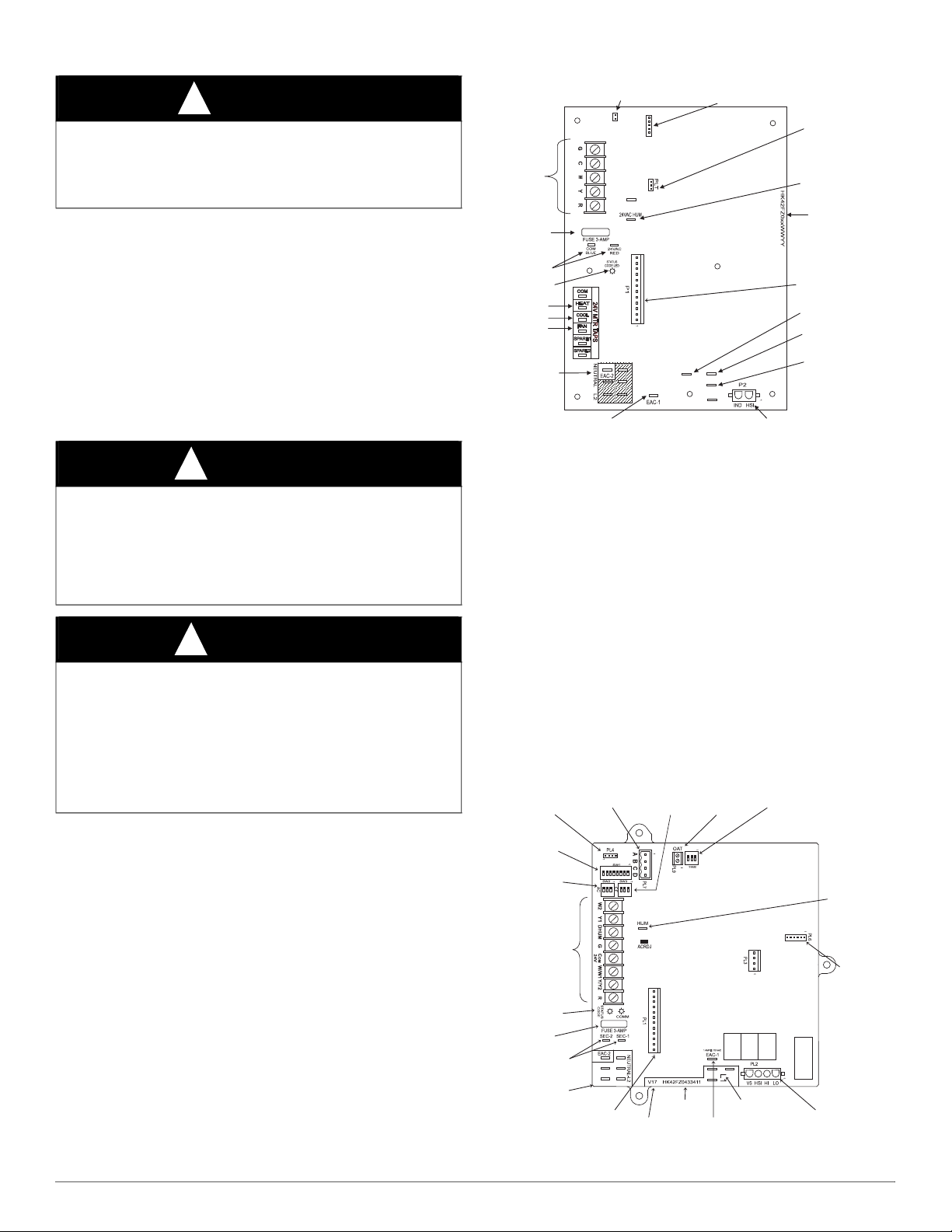
A200203
SAFETY CONSIDERATION
Installing and servicing heating equipment can be hazardous due to gas
and electrical components. Only trained and qualified personnel should
install, repair, or service heating equipment.
Untrained personnel can perform basic maintenance functions such as
cleaning and replacing air filters. Trained service personnel must
perform all other operations. When working on heating equipment,
observe precautions in the literature, on tags, and on labels attached to or
shipped with the unit, and other safety precautions that may apply.
Follow all safety codes. In the United States, follow all safety codes
including the current edition of the National Fuel Gas Code (NFGC)
NFPA No. 54/ANSI Z223.1. In Canada, refer to the current edition of the
National Standard of Canada, Natural Gas and Propane Installation
Codes (NSCNGPIC), CAN/CSA-B149.1 and .2. Wear safety glasses and
work gloves. Have a fire extinguisher available during start-up,
adjustment steps, and service calls.
Recognize safety information. This is the safety-alert symbol . When
you see this symbol on the furnace and in instructions or manuals, be
alert to the potential for personal injury. Understand the signal words
DANGER, WARNING, CAUTION and NOTE. The words DANGER,
WARNING, and CAUTION are used with the safety alert symbol.
DANGER identifies the most serious hazards which will result in severe
personal injury or death. WARNING signifies a hazard which could
result in personal injury or death. CAUTION is used to identify unsafe
practices which may result in minor personal injury or product and
property damage. NOTE is used to highlight suggestions which will
result in enhanced installation, reliability, or operation.
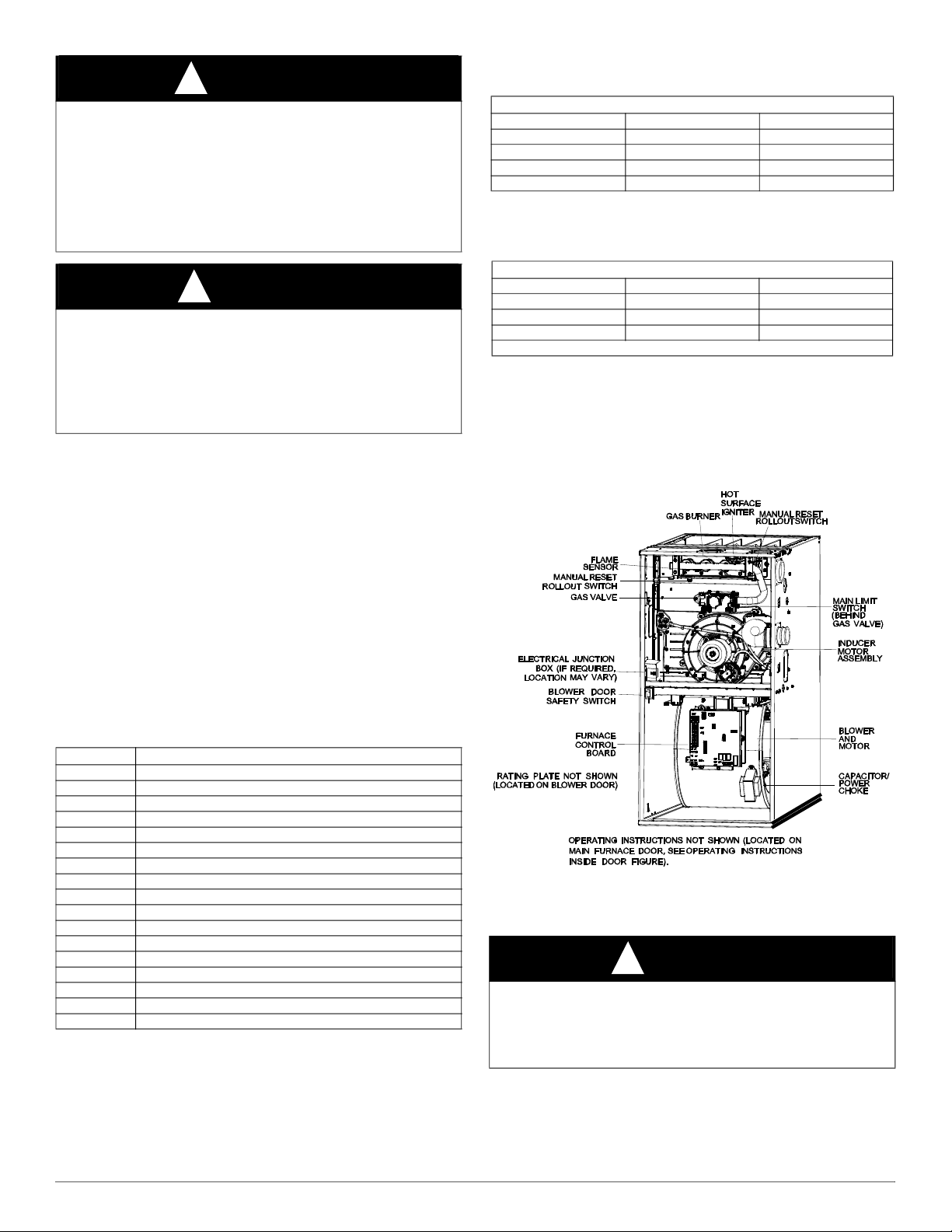
INTRODUCTION
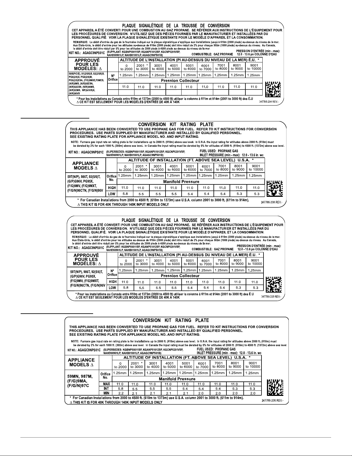
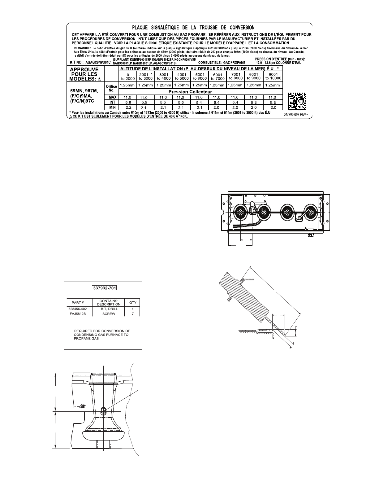
AGAGC9NPS01C
Gas Conversion Kit, Natural to Propane
Condensing (90%+) Furnaces
40,000 BTUH to 140,000 BTUH Models Only
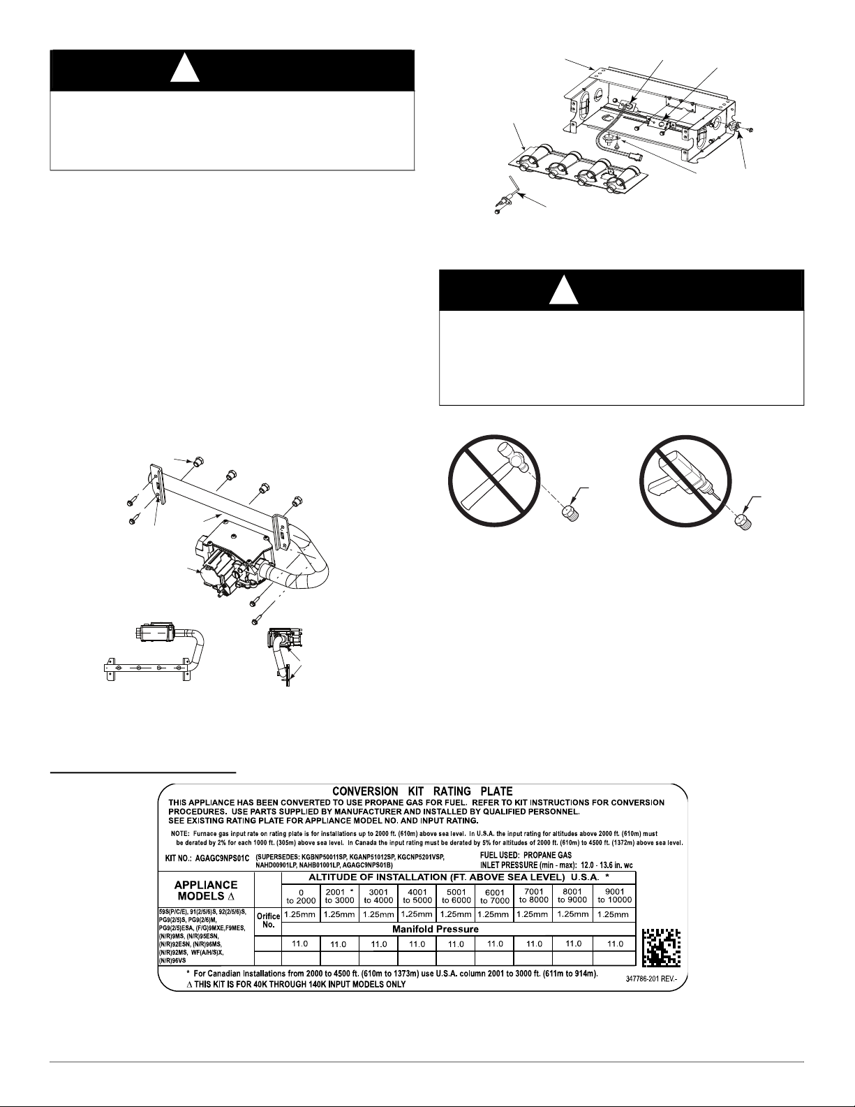
WARNING
!
FIRE, EXPLOSION, ELECTRICAL SHOCK, AND
CARBON MONOXIDE POISONING HAZARD
Failure to follow this warning could result in personal injury or death.
This conversion kit shall be installed by a qualified service agency in
accordance with the manufacturer’s instructions and all applicable
codes and requirements of the authority having jurisdiction. If the
information in these instructions is not followed exactly, a fire,
explosion, or production of carbon monoxide could result causing
property damage, personal injury, or loss of life. The qualified service
agency is responsible for the proper installation of this furnace with this
kit. The installation is not proper and complete until the operation of the
converted appliance is checked as specified in the manufacturer’s
instructions supplied with the kit
AVERTISSEMENT
!
LE FEU, L’EXPLOSION, CHOC ELECTRIQUE,
ET MONOXYDE DE CARBONE EMPOISONNER
Cette trousse de conversion doit être installée par un servie d’entretien
qualifié, selon les instructions du fabricant et selon toutes les exigences
et tous les codes pertinents de l’autorité compétente. Assurezvous de
bien suivre les instructions dans cette notice pour réduire au minimum
le risque d’incendie, d’explosion ou la production de monoxyde de
carbone pouvant causer des dommages matériels, de blessure ou la
mort. Le service d’entretien qualifié est responsable de l’installation de
cette trousse. L’installation n’est pas adéquate ni complète tant que le
bon fonctionnement de l’appereil converti n’a pas été vérfié selon les
instructions du fabricant fornies avec la trousse.
WARNING
!
FIRE, EXPLOSION, ELECTRICAL SHOCK AND
CARBON MONOXIDE POISONING HAZARD
Failure to follow instructions could result in personal injury, death or
property damage.
Improper installation, adjustment, alteration, service, maintenance, or
use can cause carbon monoxide poisoning, explosion, fire, electrical
shock, or other conditions, which could result in personal injury or
death. Consult your distributor or branch for information or assistance.
The qualified installer or agency must use only factory-authorized kits
or accessories when servicing this product.
WARNING
!
FIRE, EXPLOSION, ELECTRICAL SHOCK HAZARD
Failure to follow this warning could result in personal injury, death or
property damage.
Gas supply MUST be shut off before disconnecting electrical power
and proceeding with conversion.