Carrier 337938 -782 -CBP User manual

1
337938---782---CBP
337938---784---CBP
337938---785---CBP
337938---786---CBP
337938---787---CBP
337938---790---CBP
Installation Instructions
INDUCER HOUSING KIT
F O R S I N G L E --- S T A G E , T W O --- S T A G E A N D
MODULATING GAS FURNACES
NOTE: Read the entire instruction manual before starting the
installation.
SAFETY CONSIDERATIONS
Improper installation, adjustment, alteration, service, maintenance,
or use can cause explosion, fire, electrical shock, or other
conditions which may cause death, personal injury, or property
damage. Consult a qualified installer, service agency, or your
distributor or branch for information or assistance. The qualified
installer or agency must use factory--authorized kits or accessories
when modifying this product. Refer to the individual instructions
packaged with the kits or accessories when installing.
Follow all safety codes. Wear safety glasses, protective clothing,
and work gloves. Have a fire extinguisher available. Read these
instructions thoroughly and follow all warnings or cautions
included in literature and attached to the unit. Consult local
building codes, the current editions of the National Fuel Gas Code
(NFGC) NFPA 54/ANSI Z223.1 and the National Electrical Code
(NEC) NFPA 70.
In Canada, refer to the current editions of the National Standards of
Canada CAN/CSA--B149.1 and .2 Natural Gas and Propane
Installation Codes, and Canadian Electrical Code CSA C22.1.
Recognize safety information. This is the safety--alert symbol .
When you see this symbol on the unit and in instructions or
manuals, be alert to the potential for personal injury.
Understand the signal words DANGER,WARNING,and
CAUTION. These words are used with the safety--alert symbol.
DANGER identifies the most serious hazards which will result in
severe personal injury or death. WARNING signifies hazards
which could result in personal injury or death. CAUTION is used
to identify unsafe practices which may result in minor personal
injury or product and property damage. NOTE is used to highlight
suggestions which will result in enhanced installation, reliability, or
operation.
FIRE, EXPLOSION, ELECTRICAL SHOCK
HAZARD
Failure to follow this warning could result in personal injury,
death and/or property damage.
The ability to properly perform maintenance on this equipment
requires certain knowledge, mechanical skills, tools, and
equipment. If you do not possess these, do not attempt to
perform any maintenance on this equipment other than those
procedures recommended in the Owner’s Manual.
!WARNING
FIRE, EXPLOSION, ELECTRICAL SHOCK AND
CARBON MONOXIDE POISONING HAZARD
Failure to follow instructions could result in personal injury,
death or property damage.
Improper installation, adjustment, alteration, service,
maintenance, or use can cause carbon monoxide poisoning,
explosion, fire, electrical shock, or other conditions, which
could result in personal injury or death. Consult your
distributor or branch for information or assistance. The
qualified installer or agency must use only factory--authorized
kits or accessories when servicing this product.
!WARNING
ELECTRICAL SHOCK HAZARD
Failure to follow this warning could result in personal injury
or death.
Before installing, modifying, or servicing system, main
electrical disconnect switch must be in the OFF position and
install a lockout tag. There may be more than one electrical
supply to the furnace. Check accessories and cooling unit for
additional electrical supplies that must be shut off during
furnace servicing. Lockout and tag switch with a suitable
warning label. Verify proper operation after servicing.
!WARNING
INTRODUCTION
This instruction covers installation of the single--speed, two--speed,
and modulating inducer assemblies on condensing 35--in. (889
mm) tall, high--efficiency units.
The inducer should be replaced when the motor is seized, open,
shorted or grounded. The PSC motor is equipped with an internal
thermal overload. If the overload is open, allow time (several
minutes) for overload to reset.
ECM inducer motors do not have an internal overload and are in-
ternally protected through the electronics in the motor controller.
There are four (4) different PSC inducer assemblies to service all
single--stage and 2-stage furnaces with PSC inducers.
Each of the 4 PSC motors have a different horsepower and/or RPM
range required for the various size furnaces.
The motor supplied in the kit for furnaces with PSC inducers is a
2--speed inducer motor. Single--stage operation is achieved through
the use of an adapter harness included with the kit.
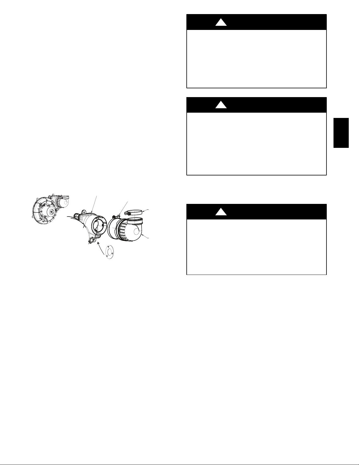
There is one (1) kit for modulating furnaces. The replacement
assembly may look different from the assembly installed on the
furnace, but operates the same as the original motor. The new
modulating furnace inducer kit does not require an adapter harness.
See Fig. 1.
Refer to Table 2 for the correct furnace and kit combination.

2
Adapter Harness
Remove and discard.
Old Style ECM Inducer
New Style ECM Inducer
A13034
Fig. 1 -- ECM Inducers
DESCRIPTION AND USAGE
Use this inducer assembly kit to replace a failed inducer assembly.
The assembly cannot be disassembled to remove or repair individual
components. The kit contains the following items shown in Table 1.
NOTE: Inducer assembly consists of motor, wheel, inducer
housing, inlet gasket, inlet choke plate and condensate drain
gasket. It will be necessary to reuse some components from the old
inducer assembly.
UNIT DAMAGE HAZARD
Failure to follow this caution may result in unit damage.
Using the incorrect inducer motor assembly could result in no
pressure switch operation, poor ignition, poor combustion,
erratic burner operation/burner pulsations, flame roll--out or
noise.
CAUTION
!
Table 1 – Kit Contents
NAME QUANTITY
Inducer Assembly 1
Installation Instructions 1
Inlet Choke Plate
(
PSC and Ultra Low NOx only
)
1--2
Inducer Outlet Restrictor
(
40,000 input only
)
1
T
w
o--stage to Single--stage Adapter Harness
(
PSC
only except 140,000 input) 1
1/2--in..
#
8 Hex Head Screws 1 /2--in. 5
3/8--in.
#
8 Hex Head Screws 2
Table 2 – Model Numbers
SINGLE SPEED PSC INDUCER MODELS
INPUT KIT NUMBER
26,000 337938--784--CBP*
40,000
60,000 337938--785--CBP*
80,000
100,000 337938--786--CBP*
120,000
140,000 337938--787--CBP*
TWO SPEED PSC INDUCER MODELS
INPUT KIT NUMBER
40,000 337938--784--CBP*
60,000 337938--785--CBP*
80,000
100,000 337938--786--CBP*
120,000
MODULATING MODELS
INPUT KIT NUMBER
60,000
337938--790--CBP*
80,000
100,000
120,000
U
L
TRA LOW NOX MODELS
INPUT KIT NUMBER
60,000
337938--790--CBP*80,000
100,000
SINGLE SPEED EXPORT MODELS (220 VO
L
T, 50 HZ ON
L
Y)
INPUT KIT NUMBER
100,000
337938--782--CBP*120,000
140,000
*All Brands
INSTALLATION
Unit Shut Down
ELECTRICAL SHOCK AND FIRE HAZARD
Failure to follow this warning could result in personal injury,
death, and/or property damage.
Turn off the gas and electrical supplies to the furnace and
install lockout tag before performing any maintenance or
service. Follow the operating instructions on the label
attached to the furnace.
!WARNING
1. Set room thermostat to lowest setting or “OFF”.
2. Disconnect power at external disconnect, fuse or circuit
breaker.
3. Turn off gas at external shut-off or gas meter.
4. Remove outer doors and set aside.
5. Turn electric switch on gas valve to OFF.
Vent Pipe Removal
NOTE: The vent pipe may be connected to the furnace at the
rubber vent pipe support. Before cutting the vent pipe, loosen the
clamps around the vent pipe coupling and move the vent pipe
away from the furnace. Support the vent pipe as close to the
furnace as possible to prevent damage to the vent system.
NOTE: If the vent pipe passes through the vent pipe coupling into
the vent elbow on the inducer, it may be necessary to cut the vent
pipe external to the casing, then re--cement the vent pipe with a
field--supplied coupling.
337938

3
1. Support the vent pipe as close to the furnace as possible to
prevent damage to the vent system.
2. Cut vent pipe with a hacksaw and move the remaining vent
pipe out of the way. Secure the vent pipe if necessary.
3. Loosen both clamps at the vent pipe support attached to
furnace casing.
4. Loosen clamp for the vent pipe at vent elbow on the inducer
assembly.
5. Remove remaining vent pipe through the top of the furnace
casing and set aside.
ELECTRICAL OPERATION HAZARD
Failure to follow this caution may result in improper
furnace operation or failure of furnace.
Label all wires prior to disconnection when servicing
controls. Wiring errors can cause improper and dangerous
operation.
CAUTION
!
D’EQUIPEMENT D’OPERATION
Toute erreur de câblage peut être une source de danger et de
panne.
Lors des opérations d’entretien des commandes, étiqueter
tous les fils avant de les déconnecter.
PRUDENCE
!
Pressure Switch or Pressure Transducer Tube
Removal
NOTE: There are two types of pressure switches. The modulating
pressure switch assembly has three pressure switches. Two are
side-by-side with the third switch mounted to the back of one of
the switches.
The Ultra Low NOx furnace uses a pressure transducer mounted to
the heat exchanger cell panel instead of a pressure switch. It is not
necessary to remove the pressure transducer when replacing the
inducer assembly.
All other furnaces have two pressure switches mounted
back-to-back.
Pressure switches for PSC inducers have a tube on the back
pressure switch that connects to the port on the inducer assembly.
Pressure switches for the modulating inducers only have one
pressure switch tube. The pressure transducer for the Ultra Low
NOx model is not connected to the inducer assembly.
1. Remove the front pressure switch or pressure transducer
tube from the port on the collector box. See Fig. 2. For
Utlra Low NOx models, go to Step 7. all other models,
continue with Step 2.
2. Disconnect the pressure switch harness (modulating only)
from the main wiring harness or remove the individual
wires from the front pressure switch (non--modulating).
Note the location of the wires for reassembly.
3. Remove the screws that attach the pressure switch assembly
to the inducer.
4. Remove the back pressure switch tube that connects to the
inducer assembly (PSC only).
5. Remove the wires from the back pressure switch. Note the
location of the wires for reassembly. (PSC only).
6. Set the pressure switches aside.
7. If the relief tube for the condensate trap or pressure
transducer tube is routed across the inducer assembly,
remove the tube from the port on the collector box and from
the stand--offs on the inducer and move the tube aside
Inducer Mounting Screw
Pressure Switch
Inducer Mounting Screw
Remove Vent Elbow
Vent Elbow Clamp
Remove Tube(s) from
Standoffs
Inducer Mounting Screw
Pressure Switch
Mounting Screw
Representative drawing only, some models may vary.
A11361
Fig. 2 -- Inducer Assembly with Pressure Switches.
(Modulating/Ultra Low NOx model is similar)
Inducer Assembly Removal
1. Remove the door bracket from the front edge of the blower
shelf.
2. Remove the wires that connect the main wiring harness to
the inducer motor harness. On furnace using an old style
ECM inducer, remove the adapter harness between the in-
ducer motor and main furnace wiring harness and discard.
See Fig. 1 and 3.
Disconnect from
ECM Motor
Disconnect from
furnace wiring harness
Disconnect from
furnace wiring harness
A12001
Fig. 3 -- ECM Adapter Harness
3. Remove the screws from the tabs on inducer assembly that
secures the inducer to the collector box. Note there is one
mounting tab directly under the vent elbow.
4. Remove the inducer assembly and set aside.
5. To avoid double gasketing and leakage, check to make sure
the drain gaskets for the inducer and the inducer gasket are
not still attached to the collector box.
6. Remove any adhered gaskets from the front of the collector
box.
7. Remove the vent elbow from the inducer assembly and set
aside.
Inducer Inlet Choke Plate (PSC and Ultra Low
NOx inducers only)
NOTE:Some PSC and Ultra Low NOx inducers have a factory--in-
stalled Inducer Inlet Choke.The Inlet Choke snapsinto theinlet of the
Inducer Assembly. A new Choke Plate is included in the loose parts
bag of the inducer kit. If a new Choke Plate is required as shown in
Table3 and is notincluded in the loose parts bag, thechoke platefrom
the old inducer assembly can be re--used in the new assembly. Modu-
lating inducer assemblies do not use an Inlet Choke Plate. See Fig.4.
337938

4
1. Un--snap the Inlet Choke from the old inducer assembly.
2. Align the tabs on the Inlet Choke collector box with the
slots on the inlet of the replacement inducer assembly and
snap into place.
A190400
Fig. 4 -- Inlet Choke
Table 3 – Inlet Choke Plate Required
SINGLE SPEED MODELS
INPUT BTUH CHOKE PLATE
USED INSIDE DIAMETER
26,000 337682--403
(
3
)
9.7 mm diameter
holes
40,000 337682--402 44.45 mm
60,000 337682--401 31.75 mm
80,000 No N/
A
100,000 337682--402 44.45 mm
120,000 No N/
A
140,000 No N/
A
TWO SPEED MODELS
INPUT BTUH CHOKE PLATE
REQUIRED INSIDE DIAMETER
40,000 337682--402 44.45 mm
60,000 337682--401 31.75 mm
80,000 No N/
A
100,000 337682--402 44.45 mm
120,000 No N/
A
U
L
TRA LOW NOx MODELS
INPUT BTUH CHOKE PLATE
REQUIRED INSIDE DIAMETER
60,000 No N/
A
80,000 No N/
A
100,000 337682--402 44.45 mm
MODULATING MODELS -- No Choke Plate Required
SINGLE SPEED EXPORT MODELS
(220 VOLT, 50 HZ ONLY)
Input BTUH Choke Plate
Required Inside diameter
100,000 337682--402 44.45 mm
120,000 No N/
A
140,000 No N/
A
Inducer Assembly Installation
1. Verify any remaining gaskets on the front of the collector
box are removed.
2. Verify the inducer assembly has gaskets on the drain stubs
and at the inducer inlet.
3. Verify the Inlet Choke Plate (when used) is installed on the
inlet opening of the inducer.
CARBON MONOXIDE POISONING HAZARD
Failure to follow this warning could result in personal injury
or death.
Missing gaskets can increase the risk of increased levels of
carbon monoxide.
!WARNING
4. Align the tabs on inducer assembly to the brass inserts on
the collector box.
5. Insert the mounting screws by hand through the tabs to se-
cure the inducer to the collector box. Remember there is a
mounting tab located under the vent elbow.
6. Tighten the screws in an alternating pattern by hand. Do not
use a screw gun or over--tighten the mounting screws.
7. Connect the inducer leads from the main wiring harness to
the inducer motor harness.
On Variable Speed furnaces with old style ECM inducers, verify
adapter harness has been removed before connecting harness to
new ECM motor (See Fig. 3). Otherwise, connect furnace wiring
harness directly to motor.
On 2-stage furnaces, connect furnace wiring harness directly to
harness on inducer motor.
On single stage furnaces (except 140,000 input), attach adapter
harness included in kit to harness on inducer motor. Connect the
other end of the adapter harness to the main furnace wiring harness.
See Fig. 5. On 140,000 input single--stage furnaces, connect
furnace wiring harness directly to harness on inducer motor.
8. Attach the vent elbow to the inducer outlet. Torque the vent
elbow clamp 15 lb--in.
A12002
Fig. 5 -- Single to Two--Stage PSC Adapter Harness
Pressure Switch or Pressure Transducer Tube
Installation
NOTE: There are two types of pressure switches. The modulating
pressure switch assembly has three pressure switches. Two are side--
by--side with the third switch mounted to the back of one of the
switches.
The Ultra Low NOx furnace uses a pressure transducer mounted to
the heat exchanger cell panel instead of a pressure switch. It is not
necessary to remove the pressure transducer when replacing the
inducer assembly.
All other furnaces have two pressure switches mounted back--to--
back.
The tube for the front pressure switch connects the switch to the port
on the collector box. The tube for the switch mounted on the back
connects the switch to the port on the inducer assembly. The pressure
transducer for the Ultra Low NOx model is not connected to the in-
ducer assembly.
1. Connect the wires to the back pressure switch (PSC only).
For Utlra Low NOx models, go to Step 3. and Step 7. all
other models, continue with Step 3.
337938

5
2. Connect the tube for the back pressure switch to the inducer
assembly (PSC only).
3. Connect the tube for the front pressure switch or pressure
transducer to the port on the collector box (PSC only).
4. Attach the pressure switch assembly to the inducer.
5. Connect the pressure switch harness (modulating only) to
the main wiring harness or attach the individual wires to the
pressure switch (non--modulating).
6. If necessary, route the pressure switch tubing for the front
pressure switch through the stand--off on the inducer
assembly.
7. If necessary, route the condensate trap relief tubing through
the stand--off on the inducer assembly. Reconnect tubing to
the ports on the condensate trap and collector box.
Inducer Outlet Restrictor (PSC models only)
On 40,000 BTUH input models on vent systems under 10 ft. in
length, an inducer outlet restrictor is required at altitudes under
2000--ft (610 M). The outlet restrictor snaps into the outlet of the
inducer assembly. If the Outlet restrictor was installed in the old
inducer, remove it and re--install it in the replacement inducer.
To install the outlet restrictor:
1. Align the lock tabs on the outlet restrictor with the slots on
inside outlet of the inducer assembly.
2. Snap the outlet restrictor in place.
3. Install the vent elbow in the required orientation.
4. Torque vent elbow clamp 15 lb--in.
PSC INDUCER ASSEMBLY
INDUCER OUTLET
VENT ELBOW CLAMP
TORQUE 15 LB-IN.
VENT PIPE CLAMP
TORQUE 15 LB-IN.
VENT ELBOW
INDUCER OUTLET CHOKE
40,000 BTUH MODELS ONLY
10 FT. OF VENT OR LESS
A150624
Fig. 6 -- Outlet Choke Installation
Vent Pipe Installation
1. Orient the vent elbow in the required location. Torque the
vent elbow clamp 15 lb--in.
2. Insert the vent pipe through the furnace casing and into the
outlet of the inducer vent elbow.
3. Tighten the clamp for the vent pipe at vent elbow on the
inducer assembly.
4. Align the remaining vent pipe system to the vent pipe in the
furnace casing.
5. Solvent cement the pipes as required for the type of material
used.
6. Tighten both clamps at the vent pipe support attached to
furnace casing.
Unit Checkout
1. Set thermostat to “OFF”.
2. Turn on power at external disconnect, fuse or circuit
breaker.
3. Turn on gas at external shut-off or gas meter.
FIRE AND EXPLOSION HAZARD
Failure to follow this warning could result in a fire, explosion,
personal injury or death.
NEVER purge a gas line into a combustion chamber. NEVER
test for gas leaks with an open flame. Use a commercially
available soap solution made specifically for the detection of
leaks to check all connections. A fire or explosion may result
causing property damage, personal injury, or loss of life.
!WARNING
RISQUE D’EXPLOSION ET D’INCENDIE
Le non--respect des avertissements de sécurité pourrait
d’entraîner des blessures graves, la mort ou des dommages
matériels.
Ne jamais utiliser une flamme nue por vérifier la présence des
fuites de gaz. Pour la vérification de tous les joints, utiliser
plutôt une solution savonneuse commerciale fabriquée
spécifiquement pur la détection des fuites de gaz. Un incendie
ou une explosion peut entraîner des dommages matériels, des
blessures ou la mort.
!WARNING
4. Check for gas leaks with a commercially available soap
solution made specifically for the detection of leaks.
5. Manually close blower door switch.
ELECTRICAL OPERATION HAZARD
Failure to follow this warning could result in personal injury
or death.
Blower door switch opens 115--v power to control. No
component operation can occur unless switch is closed.
Caution must be taken when manually closing this switch for
service purposes.
!WARNING
6. Initiate component test through circuit board by referring to
“Component Test” on status code label on blower access
door for complete test sequence information.
7. If any status codes are flashed, refer to status code label on
unit blower door.
8. Turn thermostat fan switch to “ON”, “Continuous” or
jumper R to G terminals at furnace control board.
9. Check for air leakage around cell panel.
10. Remove jumper(s) or set thermostat fan to “Auto” or “OFF”
11. Release blower door switch
12. Install blower access door
13. Set thermostat to call for heat.
14. Allow unit to initiate a complete call for heat cycle.
15. Check for air leakage around collector box. A whistling
noise may indicate air leak in collector box seal.
NOTE: If there is a severe air leak in the collector box seal,
pressure switch may not close or will re-open, resulting in no
ignition or erratic burner operation.
NOTE: As part of the system check-out, verify that the following
conditions are not affecting the operation of the furnace:
SShort Cycling-Defective thermostat: Incorrect thermostat
anticipator setting, dirty filter or over-sized furnace.
SUnder firing/low BTU input: Set manifold pressure and verify
337938

6
firing rate as shown on rating plate by clocking the gas meter.
SOver firing/high BTU input: Set manifold pressure and verify
firing rate as shown on rating plate by clocking the gas meter.
SLow temperature rise: Set unit for correct temperature rise range
as shown on unit rating plate.
SContaminated combustion air: Remove contaminates or provide
ample fresh air for combustion.
SExcessive amounts of outside ventilation air: Return air
temperature cannot be below 60 degrees F for extended periods
of time.
SIncorrect venting or termination: Recirculation of products of
combustion into the combustion air pipe can damage the
furnace. Verify proper venting and vent termination per
installation instructions. For additional information, and a
complete sequence of furnace operation, refer to furnace
Installation, Start-Up and Operating Instructions.
16. After System Check-out is complete, set thermostat below
room temperature.
17. Verify that burner shuts down and blower completes
selected off delay time.
18. Verify furnace operates properly and set thermostat to
desired room temperature.
19. Re-install outer door.
Copyright 2019 CAC / BDP D7310 W. Morris St. DIndianapolis, IN 46231 . Edition Date: 11/19
Manufacturer reserves the right to change, at any time, specifications and designs without notice and without obligations.
Catalog No:IIK---337938---07
Replaces: IIK--- 337938---06
337938
This manual suits for next models
5
Table of contents
Other Carrier Furnace Accessories manuals

Carrier
Carrier AGAGC9NPS01C User manual

Carrier
Carrier KGBPN42011SP User manual

Carrier
Carrier 337938-791-CBP User manual

Carrier
Carrier KGATW0601HSI User manual

Carrier
Carrier 337938-782-CBP User manual

Carrier
Carrier KGBPN42011SP User manual

Carrier
Carrier KGANP3001ALL User manual

Carrier
Carrier AGAGC9NPS01D User manual

Carrier
Carrier PG9YAA User manual