507827-01Issue 1813Page 2 of 4
System Operation
With this twinning accessory kit, it is important to
understand upon a call for heat from a single thermostat,
that both circulation air blowers will come on and go off
at the same time. In addition, the induced draft blowers
of both furnaces will be energized, the pressure switch of
each furnace will close, the gas valve of each furnace will
open (either high or low re depending on furnaces), and
the burners of each furnace will ignite. Thirty seconds later,
both circulation air blowers will be energized.
When the heat demand is satised, the heating relays of
each furnace are de-energized and close each furnace’s
gas valve. Both furnace circulation air blowers will continue
to run until the blower off fan period has been met.
• Single-stage furnaces twinned together with a single-
stage thermostat will operate each furnace at the
same time.
• Two-stage furnaces twinned together with a two-stage
thermostat will operate each furnace such that rst
stage heat of each furnace operates at the same time.
When second stage heat demand is needed, both
furnaces will transition to high heat at the same time.
• Two-stage furnaces twinned together with a single-
stage thermostat will utilize control boards 7.5/10 min.
stage transition. Each furnace must be set to same
setting.
Installation
To twin two gas-red furnaces, follow these directions
along with the appropriate application section and wiring
schematic.
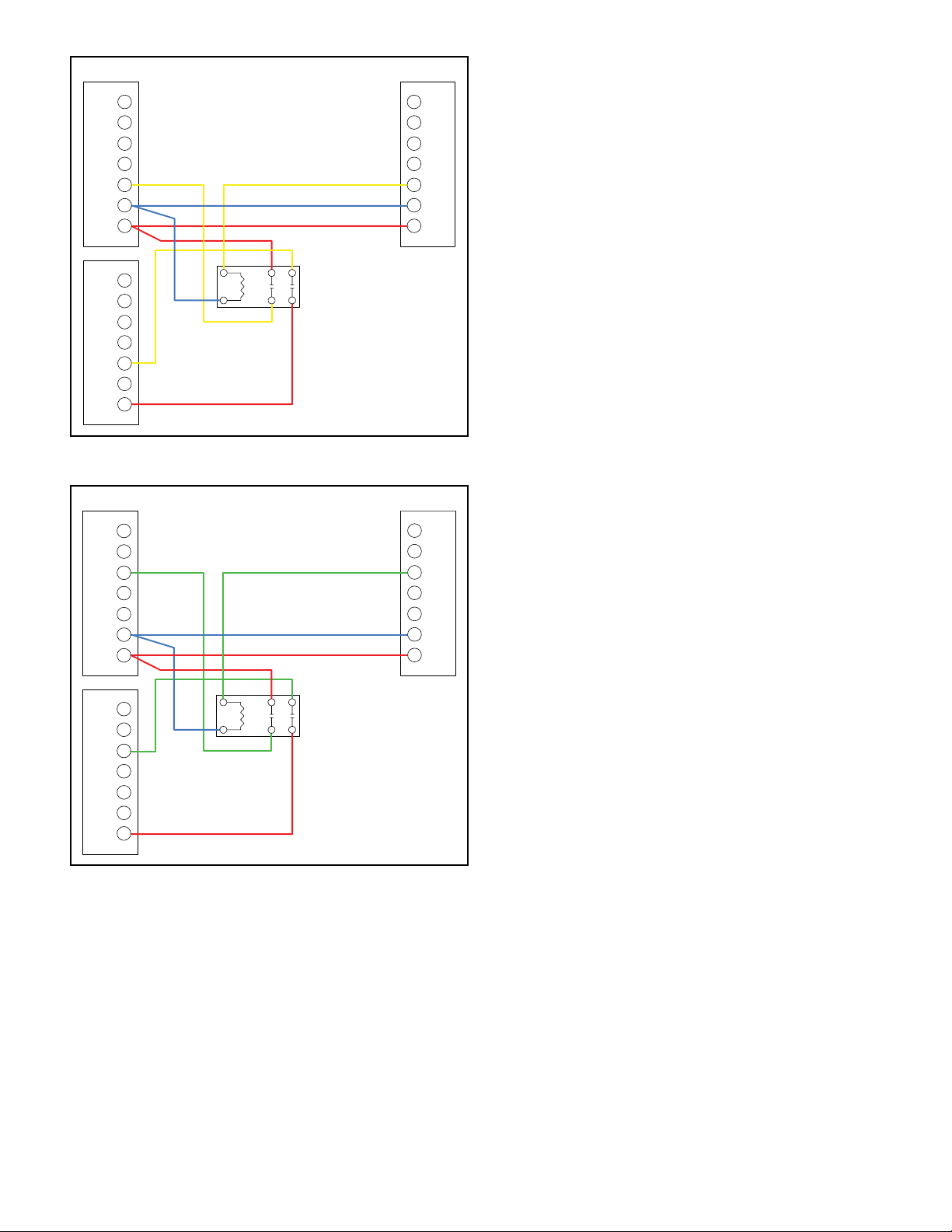
Single-Stage Heating and Cooling with Single-Stage
Thermostat
1. Mount DPST relay(s) (supplied with kit) next to the
blower control board of Furnace 1. Use kit supplied
self-tapping screws to mount DPST relay(s) to the
control bracket.
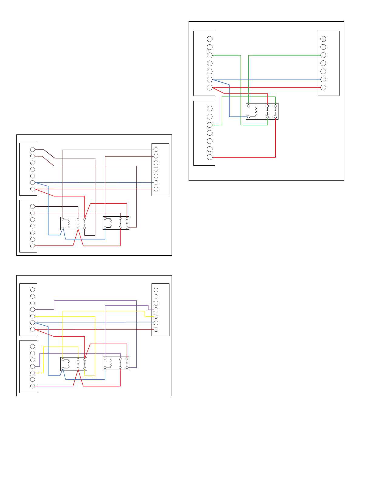
2. Connect the thermostat with Furnace 1, Furnace 2,
and the DPST relay as shown in Figure 1 through
Figure 3. Use the female quick connect terminals
supplied in kit and the proper length of 18 gauge wire
(eld supplied) to complete wiring.
3. After wiring is complete, cycle both heating and cooling
modes to verify both are working properly.
FURNACE
URNACE 2
ISO RELAY
THERMOSTAT
HEAT TWIN ONLY
W1
R
C
Y1
Y2
G
W2
W1
R
C
Y1
Y2
G
W2
W1
R
C
Y1
Y2
G
W2
Figure 1.