BSD-Racing BS805T User manual

Product Size:
Length:410mm
Width:320mm
Height:165mm
Wheelbase:305mm
Instruction Manual
SAFETY PRECAUTIONS
This radio controlled racing truck is not a toy!
This high-performance R/C vehicle is recommended for ages 14 and older.
First-time builders should seek the advice of experienced modellers before
commencing assembly.
Take enough safety precautions prior to operating this vehicle.
You are responsible for this R/C vehicle's assembly and safe operation!
!
www.bsdracing.com
Highlights:
4 Wheel Drive System
Ready Assemble Ready to Run
Auto start motor 380, more power to start the vehicle
20# class engine
No more pull start, automatically started with a PUSH button, easy and quick
7.4V 1800 mAh Ni-Mh battry
6061 T6 3mm aluminum alloy, Assembled
Auto-shift 2 Speed Transmission
Independent, Colored Coil Spring Damped Suspension Arms
27 MHz AM Radio Transmitter and Receiver, with a PUSH button on the transmitter
Adjustable Threaded, Long and Oil-filled
Sealed, Waterproof and Dustproof
High Quality, with Four (4) Bevel Gears
Precise, Sealed for the Whole Vehicle
Aluminium Alloy
BSD-RACING
MODEL :BS805T
1/10 4WD NITRO AUTOSTART TRUCK
Ground clearance:23mm
Tires size:117*43mm

1.Too ls required for buildin and mai ntenance:
Cross wrench
Hobby knife Needle nose pliers
Precision r uler
Flat and Philips screwdrive r
Hobby scissors Wi re cu tters
Thread locking compound
Do not use a power scr ew driver to install screws i nto nylon or plasti c materials. The fast
locking may heat up the screws being installed that may break the molded parts or
strip the threads during installation.
2.Additional items needed for operation:
8pcs AA a lkaline
batte ries for
transmitte r
TL
Hex wrench
CA glue & rubber cement
CA
IMP ORTAN T!
Check all the screws are tight before playing the car!
Use thread lock on all screws that work loose.
Required equipment for operation
WARNING!
350CC Fuel bottle
01
Cross wrench
B7010
BS903-084
6.0V Ni-MH 2/3A1200mAh & its charger
BS903-108
Glow igniter & its charger
B7004

1.Please assemble and install this car without children’s reach.As it includes small
and sharp parts.
2.Do not run the car on public street or highways.As it might cause serious acci-
-dents,personal injuries and property damage etc.
3.During the middle of racing and after operation,the engine and exhaust will become
HOT.Therefore please do not touch them before cooling down.
4.Please make sure everyone is using different frequencies while racing the car in the
same area.
02
Please read the instruction carefully before starting the assembly.
Install eight "AA" batteries into transmitter,making
sure the polarity is correct.
Insert the antenna into the top of the transmitter and
tighten the screw.
Turn the transmitter on and check the battery light.
If all LED's light up,the batteries are acceptable.If
only the red LED lights up,immediately replace the
batteries.
- +
AA
-AA +
+
AA
-
-AA +
+
AA
-
-AA +
+
AA
-
+
AA
-
Without permission, any company, business or user shall not change the frequency, nor increase
the capacity, nor modify the original characteristics or functions once this low frequency radio is
granted type approval certificate.
The usage of the low frequency radio shall not affect aviation safety or disturb legal communications.
Once found, it shall be stopped, and must be improved until this impact is eliminated.
The legal communications aforementioned refer to radio-communication under the
telecommunications act.
Low frequency radios must submit to disturbance produced by legal communications, and
radio-wave radiation generated by industrial, scientific and medical equipments.
TRANSMITTER PREPARATION

03
1
2
3
4
6
7
8
9
18
17
16
15
15
14
13
13
12
11
10
Install the receiver antenna.
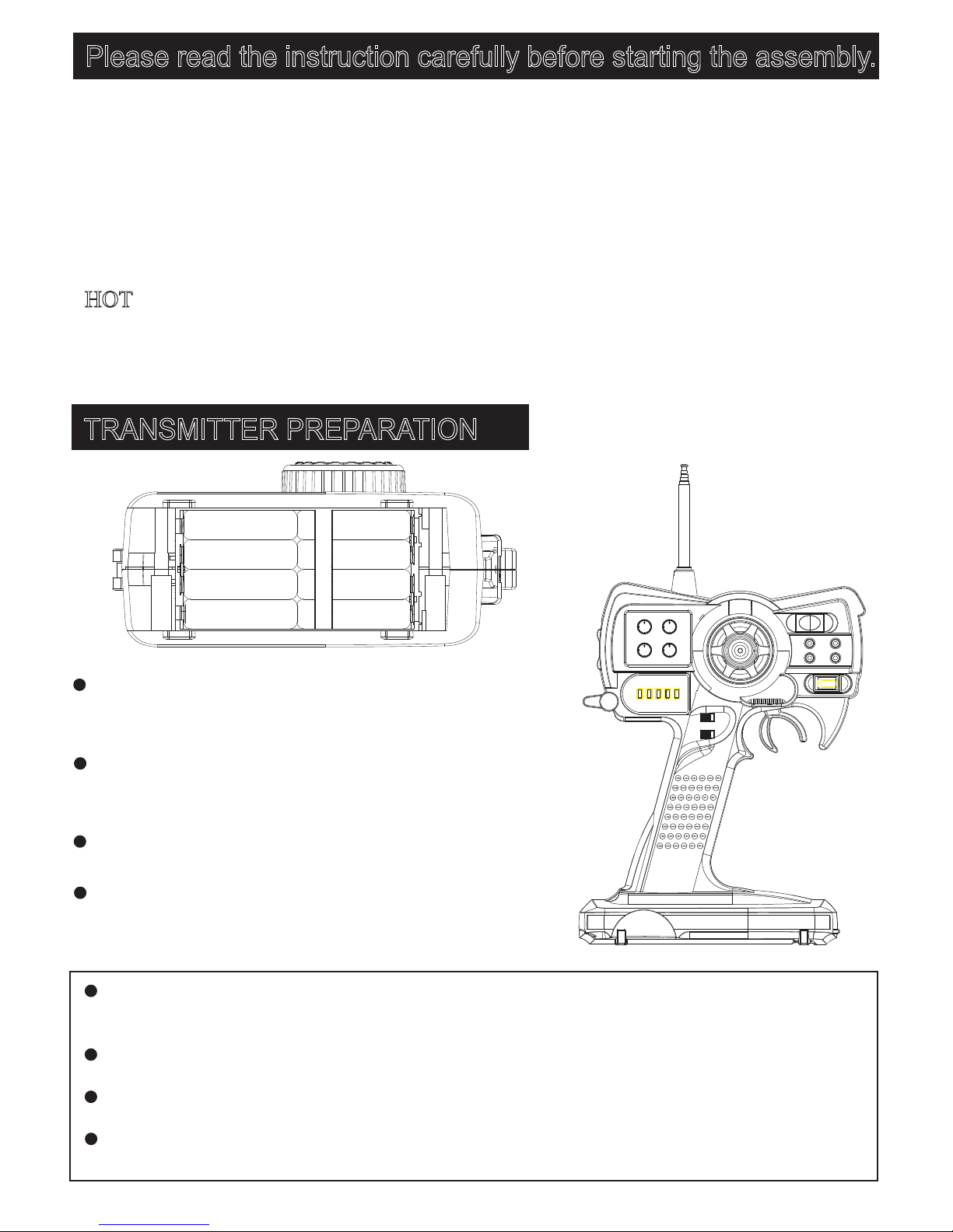
Install the transmitter antenna.
Loading the battery on the transmitter.
Install the charged battery on the truck.
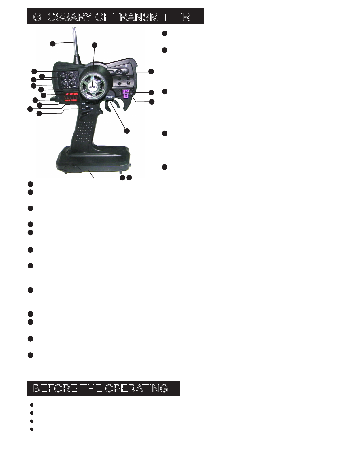
GLOSSARY OF TRANSMITTER
BEFORE THE OPERATING
Antenna: The transmitter antenna should be pulled
out completely before turning on the power switch.
Power switch: Pushing up the switch to turn on the t
ransmitter, and pressing it down to switch off. Before
driving the truck, always turn on the transmitter first,
then the receiver, and when finishing driving, always
turn off the receiver first, then the transmitter.
Power LED: These indicators are showing the power
and signal sending strength. When the battery runs
low, the indicators will be off one by one. When the
battery voltage is lower than 8.5v, low voltage indicator
flashes. Please change batteries immediately.
Wrist wrap hole: This is for installing wrist wrap,
which makes it easier to take the transmitter.
Battery charging port: When Ni-Mh batteries or Ni-CD
batteries are used, you can charge with this port.
Throttle trigger: The throttle trigger is used to control
forward, and braking.
Steering wheel: This is for controlling the left and right steering of the racing model.
3 channel power switch: Also as Autostart switch. This Autostart switch ignites the engine when it is
pressed for less than 5 seconds.
Steering D/R trim: Tune counterclockwise to reduce the steering servo angle, and clockwise to
increase the steering servo angle.
Throttle D/R trim: Tune counterclockwise to reduce the throttle, and clockwise to increase the throttle.
Steering neutral trim: Tune counterclockwise to adjust the steering to left, and clockwise to adjust the
steering to right.
Throttle neutral trim: Tune counterclockwise to adjust the throttle forward, and clockwise to adjust the
throttle backward.
Steering reverse-direction switch: Left slide the switch, then the steering wheel turns clockwise and
thesteering servo turns right direction. Right slide the switch, so the steering wheel turns
counterclockwise and the steering servo turns left direction.
Throttle reverse-direction switch: Left slide the switch, push aside the throttle trigger, then the throttle
servo turns clockwise. Right slide the switch, push aside the throttle trigger, then the throttle servo
turns counterclockwise.
Crystal cover: crystals of different frequencies can be changed here.
Throttle trigger trim: Use a flat screwdriver to tighten/loosen the screw to achieve desired throttle
trigger position.
Battery cover: Slide the cover panel to open it (With OPEN indicator on the panel); to close it, insert
thecover to the concave, then push the cover to seal it.
Battery case: Install eight (8) “AA” batteries (or rechargeable batteries) into the battery case setting
well the right polarity. When not in use, the batteries shall be taken out. When the power indicator
is weak, change the batteries.
1
3
45
6
7
8
9
10
2
11 12
14
1817
16

ENGINE TUNING GUIDE
HIGH-SPEED NEEDLE
IDLE STOP SCREW
The "idle stop" screw is located on the backside of the carburetor.This increases or
decreases the idle speed without changing the fuel mixture.The barrel should be a-
-pproximately 1mm from fully closed.
IDLE STOP
SCREW
HIGH-SPEED
NEEDLE
04
RUNNING THE ENGINE
i) STARTING THE ENGINE
IMPORTANT!Your radio system must ALWAYS be turned on and the transmitterantenna
fully extended when running the engine!
Press gently the button ( on the radio diagram) to start the engine and fill the fuel tank at
the same time.
8
1.Please pull out the transmitter antenna and then turn on the power switch first,before
turning on the receiver.
2.Please raises the tires off the ground and check if the control is responding.
3.Hold the throttle trigger to let the truck run. If it doesn't work, please adjust the throttle
servo and trim.
4.Please replace the battery,when the speed drops down.
5.When you finish the racing,please turn the receiver switch off first, then the transmitter
switch.
6.Please make sure the battery is disconnectted and remove the battery after finishing the
racing.
The "high-speed" needle is sticking up from the carburetor.This controls the fuel to air
mixture of the carburetor.The needle is pre-set for break-in from the factory at 2-1/2 t-
-urns out from fully closed.Once the engine is broken-in,the high-speed needle would
typically run from 2 to 2-1/2 turns out from closed,depending on the weather,humidity
and altitude above sea level.To richen the mixture turn the needle counterclockwise.To
lean it,turn the needle clockwise.
LOW-SPEED NEEDLE
The"low-speed" needle is the screw in the carb body opposite the throttle arm. it controls
the fuel to air mixture at low throttle settings.There is a simple way of adjusting the low
-speed needle correctly called the "pinch test."With the engine at idle,pinch the fuel line
and listen how the engine speeds up or slows down. If the engine increases its speed for
about 2 or 3 seconds and then loses speed, the needle is set correctly. If the engine loses
RPM quickly,it is set too lean and the lowspeed needle needs to be opened
(counterclockwise) to richen the mixture. Pinch again to check the mixture.If the engine
takes longer than 4 seconds to slow down, lean (clockwise) the low-speed needleand then
pinch again to check the mixture.
IMPORTANT! To insure long life and good performance from your engine,you MUST break-in the engine.
The break-in period is critical for long life of the internal parts of the engine.This should be done over the
first 5 tanks of fuel.
LOW-SPEED
NEEDLE
RC OPERATING PROCEDURES

05
BREAK IN PROCEDURE
SOME NOTES TO REMEMBER DURING BREAK-IN
1.Run with the body off.This will keep the engine cooler.
2.Keep the air clean at ALL time.
3.Run on a smooth,hard surface.An empty parking lot is perfect.
4.Use the same fuel that you will use for normal running.
5.Resist the urge to accelerate and decelerate quickly.
6.Break-in puts stress on the glow plug,You may need two on hand.
7.DO NOT overheat the engine.You can check the head temperature by using one of the
temperature gauges .
Your first tank of fuel should be running the truck at a very rich needle valve setting.This
allows the fuel to carry as much oil as possible into the engine to properly lubricate the
internal parts during the break-in.
1.Open the high speed needle valve 4-1/2 turns from fully closed (counterclockwise).This
is factory set already. But check it to make sure. When closing the high-speed needle,
close until you feel some resistance.DO NOT overtihgten or you will damage the engine.
2.Fill the fuel tank and start the engine.
3.Run the truck on a smooth surface with the body off.
4.Run back and forth at medium speeds, slowly accelerating and decelerating the truck.
5.Run the truck until the tank is almost out of fuel.Do not allow the tank to run out of
fuel during break-in.This leans out the engine and can cause overheating.
6.Stop the engine and allow it to cool.This noumally takes around 10-15 minutes.
TANK 1
IMPORTANT! FIXING A FLOODED ENGINE
If the engine is difficult to turn on, especially if it is brand new, loosen the glow plug a half
turn before starting the engine.This allows some compression to escape, but the engine will
still start.Make sure you tighten the glow plug after the engine starts.If the engine is flooded,
i.e. there is too much fuel inside the engine. Remove the glow plug, then turn the the truck
upside down. This will clear the engine fuel. Replace the glow plug and repeat the starting
procedure.
TANK 2
TANK 3
Lean the high-speed needle 1/2 turn from "tank 1" setting. Run the truck for the complete
tank and then let it cool down.
NOTE: If your engine does not stay running consistently,increase the idle speed by
turning the idle stop screw clockwise.
Lean the high-speed needle another 1/2 turn from "tank 2" setting.Run the truck for the
complete tank and then let it cool down.
ii) STOPPING THE ENGINE
Pinch the fuel line that runs to the carburetor.Pinching this line will restrict fuel flow and the
engine will quit within a few seconds.Never place your finger over the exha--ust to stop the
engine.This could result in serious burns on your finger.It also causes fuel to back up in the
engine,making it harder to start the next time you run your truck.

TANK 4
Lean the high-speed needle another 1/2 turn from "tank 3" setting. Run the truck for the
complete tank and then let it cool down.You should notice the engine running much better
at this point.
TANK 5
Lean the high-speed needle another 1/2 turn from "tank 4" setting.Run the truck for the
complete tank and then let it cool down.The engine is now ready to be performanced tuned.
06
Important! At this point,the engine will likely be running at a faster idle than needed(This
is typical after break-in). Adjust the idle stop screw to lower the idle speed so that the
wheels do not, or just barely, rotate when you lift the truck off the ground.
TUNING TIPS
After break-in,run the truck where you plan to do most of your driving (grass, street, track,
etc).Tune the high speed needle so the engine makes good power without everheating.
Using a temperature gauge, tune the engine so that it will consistently stay under 270 F
(132 C). Keep in mind.RC engines usually take a minute or two to warm up. It is common
not toreach full power right away. Never tune a cold engine!
ENGINE CARE
Never store your truck with fuel in the tank.We recommend that after the final run of the day,
you empty the fuel tank and then run the engine at idle until all the fuel is out of the fuel
lines and engine. Remove of air filter and glow plug. Then place two drops of the After Run
Engine Oil in the carburetor and two into the cylinder to help prevent corrosion.
10 WAYS TO ENSURE LONG LIFE FOR YOUR ENGINE
1.Keep your engine and air filter clean.Dirt will act as insulation on an engine. it will not
be able to shed heat as easily.Clean and re-oil the elenent often.
2.Do not over-lean your engine.
3.Do not run your engine with little or no load.Don't throttle up the engine to full throttle
when the wheels are not in contact with the ground.
4.Do not overheat the engine.
5.Do not use a fuel with a low oil content.Make sure you usea a model car fuel from a re-
-putable manufacturer,such as O'Donnell Fuels.
6.Avoid using old fuels in the engine.
7.Do not use a fuel with a nitromethane(often called niteo) content over 20%.
8.Do not scratch the piston or cylinder sleeve.Avoid jamming something into the exhaust
port when removing or re-installing the clutch or flywheel.Use a special tool called the
Ultimate Flywheel Wrench to keep the crankshaft from moving.
9.Do not use silicone sealer on the engine joints.Silicone sealer contains acetic acid,which
is corrosive if it gets inside your engine.
10.Do not allow any water to get inside the engine.This sounds easy,but temperature cha-
-nges can cause condensation inside the engine.This is a good reason to use an after-run
oil.Store your engine inside the house,not in a garage or shed where will be temperature
extremes.

BS903-003 Shock absorber
unit(plastic) 2pc BS903-005 Brace 1pcs BS903-007 Body pin 2pcs BS903-008 Upper Susp.
Arm Set 2PCS
BS903-010 Supension arm
mount block 2pcs
BS903-011 Upper susp.arm
mout-Fr/Rr
BS903-014 Ball Bearing
(6*12*4) 2PCS
BS903-015 Lf/Rt steering
arm
BS903-017 Lf/Rt C-carrier
BS903-016 Ball Bearing
(10*15*4) 2PCS
BS903-018 Fr.lower susp.
arm-Lf/Rr
BS903-019 Drive shaft set
2PCS
BS903-020 Diff.gearbox
unit
BS903-023 O-washer 4pcs
BS903-025 Suspension arm
pin-long 4pcs
BS903-024 Front suspension
arm pin-short 4pcs
BS903-026 Front chassis
BS903-028 Lower susp.
mount block-Fr/Rr
BS903-029 Anti-roll bar
fixation set
φ3*56mm
φ3*37.5mm
BS903-027 Centre Drive
Shaft-Fr.
BS903-047 Centre gearbox
unit
BS903-050 Engine flywheel
W/pin
BS903-051 Engine
crankshaft W/E-clip
BS903-052 Clutch show
w/spring
BS903-053 Clutch bell
(18T)
BS903-054 Exhaust manifold
BS903-058 Hub Rear
Carrier-Lf/Rr
BS903-059 Rr.Lower Susp.
Arm-Lf/Rr
BS903-061 Rear suspension
arm pin-short
φ3*34.5mm
BS903-065 Flat Cross
Screw(TPF2.6*10) 12PCS
BS903-066 Flat Cross Screw
(TPF3*8) 12PCS
BS903-067 Flat Cross Screw
(TPF3*10) 12PCS
11
BS903-013 Axle w/pin 2pcs
BS903-012 Rim hub w/pin 2*10 4pc
MPO-01 Wheel Hex set(AL6061) 4pc
BS903-022 M4 Self-lock nut 4pcs
w/washer 4pcs

BS903-080 Cap Head Hexagon
Screw(HM3*25) 6PCS
BS903-081 Cap Head Hexagon
Screw(HM3*10) 6PCS
BS903-082 Diff. Outdrive
C
BS903-094 Double Way Ball
end(7*8) 6PCS
BS903-097 Diff. Gearbox
BS903-098 Diff.gearbox
bulkhead-upper/lower
BS903-099 Gearbox bulkhead
-Fr/Rr
BS903-100 Spur geer/spring/
nylon self-lock nut
BS903-106 Screw Pin
(M3*9.5)
BS903-091 Washer A(5.2*
10*0.2) 12PCS
BS903-092 Washer B(4.2*8
*0.2) 12PCS
BS903-069 Flat Cross Screw
(TPF3*16) 12PCS
BS903-070 Flat Cross Screw
(ISO3*10) 12PCS
BS903-071 B-Head Cross Screw
(BT2.6*6) 12PCS
BS903-072 B-Head Cross Screw
(BT3*8) 12PCS
BS903-077 B-Head Cross Screw
(BT2.6*10) 12PCS
BS903-076 B-Head Cross Screw
(BT3*20) 12PCS
BS903-075 B-Head Cross Screw
(BT3*16) 12PCS
BS903-074 B-Head Cross Scre
(BT3*14) 12PCS
BS903-073 B-Head Cross Screw
(BT3*12) 12PCS
BS903-078 B-Head Cross Screw
(BT4*8) 12PCS
BS903-083 Diff. Outdrive
D
BS903-090 Pin(2*12.5)
12PCS
BS903-095 Set Screw(M4*4)
6PCS
BS903-101 Pinion Gear
-18T/19T BS903-103 Gear-40T/37T BS903-104 Diff. Unit
BS903-105 Driving/Driven
Gear, Diff.Gear/Bevel Gears
BS903-086 Ball Bearing
(5*10*4) 2PCS
BS903-087 Ball Bearing
(12*18*4) 2PCS
BS903-088 E-Clip(4*0.6)
12PCS
BS903-089 Pin(2*9.5)
12PCS
BS903-079 B-Head Cross Screw
(BM3*10) 12PCS
12
BS903-068 Flat Cross Screw
(TPF3*14) 12PCS
BS903-093 M4 nut 6pcs

BS803-012 Centre Drive
Shaft-Fr
BS902-051 B-Head Cross
Screw(BT3*10) 12PCS
BS904-003 Bumper 2PCS BS905-009 Anti-roll Bar
Set
BS901-067 Antenna Pipe
W/Cap 3pcs
BS902-031 Air Filter W/
Insert
BS901-066 M3 locknut
5pcs
BS903-110 Diff.outdrive
B/Pin(2*10)
BS702-047 Antenna mount
BS702-057 B-Head Cross
Screw(BM3*6) 12PCS
BS801-008 Fr/Rr Body
Mount
BS908-004 Bumper brace
-Fr
BS908-005 Bumper brace-Rr
BS908-006 Bumper chassis
-Fr
B7014 3kgs Servo B7018 9kgs Servo BS805-001 Chassis
BS805-005 Upper Deck
-Rear
BS805-006 Handle W/Fuel
Pipe Hoop
BS805-010 Steering Servo
Horn and Linkage BS805-011 20# Engine
(W/O pull start) BS805-012 Engine Mount
BS805-013 Exhaust Fixation
Set 2PCS
BS805-008 Steering Linkage
Set 2PCS
BS805-009 Steering Servo
Mount
BS805-007 Servo Saver Unit
BS805-002 Side Guard
Plate-Lf
BS805-003 Side Guard
Plate-Rt
BS805-004 Lf/Rt Upper
Deck-Centre
BS908-007 Bumper chassis
-Rr
BS908-008 Body shell
(painted) B7057 Autostart 3ch
radio unit
B7058 Autostart receiver
13
BS903-109 Diff.outdrive
A/Pin(2*10)
BS908-002 Nailed tyre
unit(chromed) 2pcs

BS805-021 7.2V Battery
Pack (Ni-Mh)1800mah
BS805-025 Brake Set BS805-026 Throttle Servo
Horn and Linkage Set BS805-027 Throttle servo
horn/servo pivot
BS805-017 Auto start gear
14T/38T/44T
BS805-018 380 Motor / 9T
motor gear
BS805-023 Fuel hose
BS805-028 Engine mount
block/Screws 4 pcs
BS805-029 Upper Deck-Fr
BS805-022 100cc-Fuel Tank
Unit
BS805-024 Throttle
Linkage Set
BS805-019 Switch/switch
cover/screw
BS805-016 Auto start gearbox
cover-Front & Rear
BS805-020 B-Head Cross Screw
(BM2.6*20) 12PCS
14
BS805-015 Auto start
gearbox unit
BS805-014 Metal pipe/Exhaust
Pipe Coupler

OPTIONAL PARTS/UPGRADE PARTS
MPO-04 Rear Hub set
Stainless steel AL6061
MPO-01 Wheel Hex Set
Stainless steel AL6061
MPO-02 C HUB C HUB W/Pin
MPO-06 Front suspension
mount
Stainless steel AL6061
MPO-07 Rear suspension
mount
Stainless steel AL6061
BS903-096 Set Screw
(M4*8) 6PCS
BS805-030 Crystal 4 BS805-031 Crystal 6-one
set
BS805-032 Crystal 8-one
set
BS903-004 Shock Absorber
Unit(Alum.) 2PCS
Stainless steel AL6061
MPO-03 Knuckle Arm Se
MPO-08 Steel brake disk
Stainless steel
Stainless steel
MPO-09 Special brake
pads
MPO-11 Steering link
Stainless steel AL6061
MPO-13 Sipper system
(hard andozie)
15
MPO-05 Shock stay mount
Stainless steel AL6061
MPO-10 Brake post

PARTS LIST
7
Item No. DescriptionItem No. Description
BS903-003 Shock Absorber Unit(Plastic) 2PCS
BS903-005 Brace
BS903-007 Body Pin 2PCS
BS903-008 Upper Susp. Arm Set 2PCS
BS903-010 Suspension Arm Mount Block 2PCS
BS903-011 Upper susp. Arm Mount-Fr/Rr
BS903-012 Rim Hub W/Pin(2*10) 4PCS
BS903-013 Axle W/Pin
BS903-014 Ball Bearing(6*12*4) 2PCS
BS903-015 Lf/Rt Steering Arm
BS903-016 Ball Bearing(10*15*4) 2PCS
BS903-017 Lf/Rt C-Carrier
BS903-018 Fr.Lower Susp.Arm-Lf/Rt
BS903-019 Drive shaft set 2PCS
BS903-020 Diff. Gearbox Unit
BS903-022 M4self-lock nut w/washer 4PCS
BS903-023 O-Washer 4PCS
BS903-024 Front Suspension Arm Pin-Short 4PCS
BS903-025 Suspension Arm Pin-Long 4PCS
BS903-026 Fr. Chassis
BS903-027 Centre Drive Shaft-Fr.
BS903-028 Lower Susp. Mount Block-Fr/Rr
BS903-029 Anti-roll Bar Fixation Set
BS903-047 Centre Gearbox Unit
BS903-050 Engine Flywheel W/Pin
BS903-051 Engine Crankshaft W/E-Clip
BS903-052 Clutch Shoe W/Spring
BS903-053 Clutch Bell(18T)
BS903-054 Exhaust Manifold
BS903-058 Hub Rear Carrier-Lf/Rr
BS903-059 Rr.Lower Susp.Arm-Lf/Rr
BS903-061 Rear Suspension Arm Pin-Short
BS903-065 Flat Cross Screw(TPF2.6*10) 12PCS
BS903-066 Flat Cross Screw(TPF3*8) 12PCS
BS903-067 Flat Cross Screw(TPF3*10) 12PCS
BS903-068 Flat Cross Screw(TPF3*14) 12PCS
BS903-069 Flat Cross Screw(TPF3*16) 12PCS
BS903-070 Flat Cross Screw(ISO3*10) 12PCS
BS903-071 B-Head Cross Screw(BT2.6*6) 12PCS
BS903-072 B-Head Cross Screw(BT3*8) 12PCS
BS903-073 B-Head Cross Screw(BT3*12) 12PCS
BS903-074 B-Head Cross Screw(BT3*14) 12PCS
BS903-075 B-Head Cross Screw(BT3*16) 12PCS
BS903-076 B-Head Cross Screw(BT3*20) 12PCS
BS903-077 B-Head Cross Screw(BT2.6*10) 12PCS
BS903-078 B-Head Cross Screw(BT4*8) 12PCS
BS903-079 B-Head Cross Screw(BM3*10) 12PCS
BS903-080 Cap Head Hexagon Screw(HM3*25)6PCS
BS903-081 Cap Head Hexagon Screw(HM3*10)6PCS
BS903-082 Diff. Outdrive C
BS903-083 Diff. Outdrive D
BS903-086 Ball Bearing(5*10*4) 2PCS
BS903-087 Ball Bearing(12*18*4) 2PCS
BS903-088 E-Clip(4*0.6) 12PCS
BS903-089 Pin(2*9.5) 12PCS
BS903-090 Pin(2*12.5) 12PCS
BS903-091 Washer A(5.2*10*0.2) 12PCS
BS903-092 Washer B(4.2*8*0.2) 12PCS
BS903-093 Nylon Self-lock Nut(M4) 6PCS
BS903-094 Double Way Ball end(7*8) 6PCS
BS903-095 Set Screw(M4*4) 6PCS
BS903-097 Diff. Gearbox
BS903-098 Diff. Gearbox Bulkhead-Upper/Lower
BS903-099 Gearbox Bulkhead-Fr./Rr.
BS903-100 Spur Gear-39T
BS903-101 Pinion Gear-18T/19T
BS903-103 Gear-40T/37T
BS903-104 Diff. Unit
BS903-105 Driving/Driven Gear, Diff.
Gear/Bevel Gears
BS903-106 Screw Pin (M3*9.5)
BS903-109 Diff.outdrive A/Pin(2*10)
BS903-110 Diff.outdrive B/Pin(2*10)
BS702-047 Antenna mount
BS702-057 B-Head Cross Screw(BM3*6) 12PCS
BS801-008 Fr/Rr Body Mount
BS803-012 Centre Drive Shaft-Fr
BS901-066 M3 locknut 5pcs
BS901-067 Antenna Pipe W/Cap 3pcs
BS902-031 Air Filter W/Insert
BS902-051 B-Head Cross Screw(BT3*10) 12PCS
BS904-003 Bumper 2PCS
BS905-009 Anti-roll Bar Set
BS908-002 Tire unit(chromed)

PARTS LIST
1 0
Optional parts/Upgrade parts
BS805-030 Crystal 4
BS805-031 Crystal 6-one set
BS805-032 Crystal 8-one set
BS903-004 Shock Absorber Unit(Alum.) 2PCS
BS903-096 Set Screw(M4*8) 6PCS
MPO-01 Wheel Hex Set
MPO-02 C hub / C hub with pin(Upgrade)
MPO-03 Knuckle Arm set(Upgrade)
MPO-04 Rear hub set(Upgrade)
MPO-05 Shock stay mount(Upgrade)
MPO-06 Front suspension mount(Upgrade)
MPO-07 Rear suspension mount(Upgrade)
MPO-08 Steel brake disk(Upgrade)
MPO-09 Special brake pads(Upgrade)
MPO-10 Brake post(Upgrade)
MPO-11 Steering link (Upgrade)
MPO-13 Sipper system(hard anodized)(Upgrade)
BS908-004 Bumper brace-Fr
BS908-005 Bumper brace-Rr
BS908-006 Bumper chassis-Fr
BS908-007 Bumper chassis-Rr
BS908-008 Body shell (painted)
B7057 Autostart 3ch radio unit
B7058 Autostart receiver
B7014 3kgs Servo
B7018 9kgs Servo
BS805-001 Chassis
BS805-002 Side Guard Plate-Lf
BS805-003 Side Guard Plate-Rt
BS805-004 Lf/Rt Upper Deck-Centre
BS805-005 Upper Deck-Rear
BS805-006 Handle W/Fuel Pipe Hoop
BS805-007 Servo Saver Unit
BS805-008 Steering Linkage Set 2PCS
BS805-009 Steering Servo Mount
BS805-010 Steering Servo Horn and Linkage
BS805-011 20# Engine(W/O pull start)
BS805-012 Engine Mount
BS805-013 Exhaust Fixation Set 2PCS
BS805-014 Metal pipe/Exhaust Pipe Coupler
BS805-015 Autostart gearbox unit
BS805-016 Autostart gearbox cover-Front & Rear
BS805-017 Auto start gear 14T/38T/44T
BS805-018 380 Motor / 9T motor gear
BS805-019 Switch/switch cover/screw
BS805-020 B-Head Cross Screw(BM2.6*20)12PCS
BS805-021 7.2V Battery Pack (Ni-Mh1800mah)
BS805-022 100cc-Fuel Tank Unit
BS805-023 Fuel hose
BS805-024 Throttle Linkage Set
BS805-025 Brake Set
BS805-026 Throttle Servo Horn and Linkage Set
BS805-027 Throttle servo horn/servo pivot
BS805-028 Engine mount block/Screws 4 pcs
BS805-029 Upper Deck-Fr
Item No. DescriptionItem No. Description

B7057
BS803-012
BS903-027
EXPLODED VIEW
BS903-018
BS903-003
BS903-004
BS903-075
BS903-074
BS903-111
BS903-095
BS903-111
BS903-014
BS903-016
BS903-017
BS903-008
BS903-069
BS903-073
BS903-005
BS903-007 BS903-074 BS903-003
BS903-004
BS903-075
BS903-014
BS903-017
BS903-076 BS903-016
BS903-072
BS903-011
BS903-019
BS903-026
BS903-096
BS903-018
BS903-010
BS903-020
BS905-009
BS903-023
BS903-024
BS903-029
BS903-024
BS903-023
BS903-024
BS903-096
BS903-029
BS903-094
BS805-008
BS903-068
BS903-028
BS903-025
BS903-073
BS805-008
BS903-068
BS903-070
BS903-014
BS903-058
BS903-015
BS903-014
BS903-058
BS903-015
BS903-075
BS903-003
BS903-004
BS903-074
BS903-023
BS903-029
BS903-059
BS903-061
BS903-019
BS903-096
BS903-028
BS903-029
BS903-008
BS903-069
BS903-011
BS903-005
BS903-076
BS903-010
BS902-051
BS905-009
BS903-020
BS903-025
BS903-025
BS903-059
BS903-073
BS903-061
BS903-023
BS903-074
BS903-003
BS903-004
BS903-075
BS901-067
BS903-003
BS903-004
BS903-098
BS903-092
BS903-087
BS903-097
BS903-104
BS903-097
BS903-091
BS903-065
BS903-087
BS903-098
BS903-086
BS805-030(4#)
BS805-031(6#)
BS805-032(8#)
B7058
BS903-105
BS903-105
BS903-105
BS903-105
BS903-109
BS903-020
BS903-065
BS903-110
BS903-110
BS908-002
BS903-013
BS903-012
BS903-022
BS903-093
BS908-002
BS903-013
BS903-012
BS903-022
BS903-093
BS908-002
BS904-003
BS908-004
BS908-006
BS903-073
BS903-073
BS902-051
BS904-003
BS908-005
BS908-007
BS903-075
BS902-051
BS903-073
BS903-013
BS903-012
BS903-022
BS903-093
BS903-013
BS903-012
BS903-022
BS903-093
BS801-008
BS801-008
BS903-008
BS903-007
BS903-007
BS903-008
BS903-082
BS903-102
BS903-095 BS903-099
BS903-086
BS903-088
BS903-101
BS903-086
BS903-099
BS903-090 BS903-100
BS903-086
BS903-103
BS903-103
BS903-083
BS806-014
BS903-080
BS903-054
BS908-008
BS903-047
BS903-050
BS903-052
BS903-051
BS903-053
BS805-011
BS805-021
BS908-002
BS908-002
BS702-047
BS903-079
BS805-022
BS903-051
BS903-106
BS805-007
BS903-047
BS805-015
BS805-015
BS805-018
BS805-016
BS805-016
BS805-017
BS805-020
BS805-023
BS805-029
BS902-031
BS903-072
BS903-072
BS805-001
BS805-003
BS805-002
BS805-004
BS805-004
BS805-005
BS805-006
BS805-009
B7014
B7014
BS805-012
BS805-013
BS805-019
BS805-024
BS805-025
BS903-106
BS702-057
BS805-010
BS902-051
BS902-051
BS903-076
BS902-051
BS902-051
BS902-051
BS903-073
BS903-074
BS903-066 BS903-070
BS903-070
BS903-067
BS901-066
BS805-026
BS805-027
BS902-051
BS902-051
BS903-067
BS903-067
BS903-067
BS903-067
BS903-067
BS903-066
BS805-028
BS902-051
BS903-079
BS903-067
8 9

Table of contents
Other BSD-Racing Motorized Toy Car manuals

BSD-Racing
BSD-Racing BT1001 User manual

BSD-Racing
BSD-Racing BS213T User manual

BSD-Racing
BSD-Racing BS810T User manual

BSD-Racing
BSD-Racing BS909T User manual

BSD-Racing
BSD-Racing BS213T User manual

BSD-Racing
BSD-Racing BS709T 1/10 2WD EP User manual

BSD-Racing
BSD-Racing Ramasoon User manual

BSD-Racing
BSD-Racing BS221T User manual

BSD-Racing
BSD-Racing RAMASOON BS916T User manual
Popular Motorized Toy Car manuals by other brands

Associated Electrics
Associated Electrics RC10B5M Factory Lite Team Kit Manual & catalog

Power Wheels
Power Wheels FVB13 owner's manual

ECX
ECX Ruckus ECX2000S Manuel d'utilisation

Jamara
Jamara Ride on Aprilia Dorsoduro 900 instructions

Carson
Carson Gas Devil 304015 instruction manual

Italeri
Italeri 3908 manual