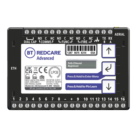
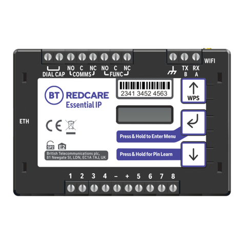
BT Redcare Essential Extra User manual

Essential Extra
Installation Guide

Contents
2 Introduction
5 Mounting And Wiring
9 Programming
16 Configuration
48 Disposal
49 Glossary Of Terms
50 Support

Introduction

3
Product Description
Figure 1 – Essential Extra unit (not to scale)
Essential Extra is a wireless dual path alarm signalling unit for transmitting alarm signals from a customer’s alarm panel,
via the BT Redcare network, to an Alarm receiving Centre (ARC). Essential Extra units have dual modems with 4G/2G
mobile technology in each path. The units are designed for use in both Security and Fire systems.
The unit communicates via the BT Redcare Network and a valid TA account must exist for the unit to communicate.
The TA account will have been populated with the serial number of the unit.
The unit has 16 general purpose alarm inputs, and 3 outputs, making it suitable for connection to most common alarm
panels.
The unit is supplied already fitted with two BT Redcare enabled SIM cards, one an EE UK fixed SIM and a UK Roaming SIM.
Both enabled for 4G/2G connectivity.

4
Specifications
Size: 114mm x 67mm x 20mm
Power: 9V – 30V
Current:
Alarm inputs: 16 General purpose inputs 1-16. (-0.5V – 30V)
Alarm threshold: High >2V, and Low <1.3V
Outputs: 3 x Relay NO C NC (Comms, Func, Fire)
RS232 port: remote panel access (UDL) and signalling to some intruder panel types
RS485 port: remote panel access (UDL) and signalling to some intruder panel types
Configuration: Using on board configuration buttons, web portal or App
Processor: STM32
Wireless modules: ELS61
Average Average Max loading
Normal Operation (inc relays and dial capture operated)
4G/4G unit @12V 110mA 190mA
4G/4G unit @24V 50mA 110mA

Mounting and Wiring

6
Removal of Cover
The top cover can be removed by gently releasing each of the 4 clips on the base of the unit by pushing the clips outward
with a screwdriver blade.
Regular access to the inside of the unit should not be required, although occasional access may be required to access the
SIM cards.
Mounting
The unit should be mounted inside the alarm panel, or inside a separate powered housing, using the sticky mounting pads
supplied.
For security installations the enclosure must meet or exceed the protection requirements of the particular security grade
for the whole installation as per EN 50131-1.
For fire alarm panels the enclosure must meet the requirements of EN 54-21 7.3 (eg. IP30 or above). Enclosure
requirements for the signalling unit are the same as for the fire alarm panel itself and must meet EN 54-2. The enclosure
must restrict access to installer level 3. The enclosure must provide the facility to indicate the state of the fault and
acknowledge outputs on the signalling unit.
The supplied aerial should be mounted vertically outside of the housing by removing the adhesive backing.
Figure 2 - Layout of terminals (not to scale)

7
Connection Terminals
The screw terminals for the alarm inputs are suitable for use with a standard 3mm blade terminal screwdriver.
Power connections
Power to the unit is via 2 screw terminals at the centre, with positive to the right nearest Pin 9.
The supply voltage range is 9V to 30V. The unit is designed to be connected to the auxiliary power output on an
associated alarm panel, or separate powered enclosure. For use with intruder alarm panels the power supply must meet
the requirements of EN 50131-6.
For use with Fire alarm panels the power supply must meet the requirements of EN 54-4 and the unit must be mounted
in the same enclosure as the power supply from which it derives its power. Ensure the power source is sufficient to power
all devices connected. See the power requirements in the specification section for more information. The account at the
Alarm Receiving Centre (ARC) should be put “on test” before power up, as signals will be sent following initialisation.
Alarm inputs
The unit has 16 alarm inputs which are presented on screw terminals along the bottom of the unit. These are labelled as
Pin 1-8 and 9 -16
By default the 16 alarm inputs require a positive condition to be presented to send an alarm. (Default = Positive applied).
This can be changed using the Pin Learn button or through the configuration menu. See later section on configuration.
1
2
3
4
5-10
11
13
14-16
Fire alarm (When programed Fire NAK and ACK outputs operate in conjunction with pin 1)
Fire Fault or Hold up alarm
Intruder alarm
Open / Close (Set / Unset) (Func out put can be set up as RPS in conjunction with pin 4)
General alarm
ATS input (BSIA F175 mode) (Can be reprogrammed as a normal alarm pin)
AC Fail alarm (has a 7 minute delay which can be altered in programming)
General alarm
Input (PIN) Use
Fig 3 - Alarm input allocations. (Functions must be agreed with your ARC)

Outputs
Three relay outputs are provided on screw terminals at the top of the unit
Output 1 is Comms, Output 2 is Func, and Output 3 is Fire.
For fire alarm installations the indication of ‘acknowledgement of fire alarm’ and ‘SPT fault’ messages must be provided by
the fire panel into which the SPT is mounted. System fault indications which are notified by the line fault output
(Output 1) must be latched by the fire panel as required by EN 54-21.
See the further sections on outputs for a full explanation.
Serial data connections
The serial data connection labelled TX, RX, B and A is configurable for RS485 or RS232 connection depending on the
panel.
This is done in the configuration menu.
These ports allow serial alarm panel connection. See Panel Upload Download section.
Dial capture
The dial capture (Dial Cap) terminals enable interfacing with an alarm panel’s digital communicator. The alarm panel can
then send SIA, CID or Fast Format messages through the unit to the Alarm Receiving Centre.
Dial capture can also be used for upload download UDL allowing remote access with some types of alarm panel.
Aerial connection
Connect the supplied aerials to the MMCX connectors on the top right of the unit. The aerials should be placed in a
vertical position and slightly apart to ensure a good wireless coverage. Carry out a survey to establish the best location.
If necessary, a selection of high gain and extension aerials can be purchased from the BT Redcare shop at
https://www.btinstallershop.com
8
Mobile 1 Aerial
Mobile 2 Aerial

Programming

10
Unit Initialisation
The unit will immediately attempt to connect to the BT Redcare platform over the configured paths. The unit will typically
complete path establishment in the following times from power up.
Figure 4 – time to commission paths after unit power up
Status display
The unit clearly displays its status on the OLED.
In its normal working state, the unit will cycle its display
Mobile 1 120s
Mobile 2 180s
Mobile2 Operator
Three
Path: Mobile2
Registered
Path: Mobile1
Registered
Mobile2 Strength
4G [ ] [-101]
Mobile1 Strength
4G [ ] [-103]
Mobile1 Operator
EE
Mobile1 Path and if registered with the platform. Mobile2 Path and if registered with the platform.
Mobile1 operator .This will always be EE Mobile2 Operator. This could be any of the main
UK networks
Signal strength – network type (4G or 2G) received
wireless signal strength in dBm and signal strength
indicator bars. 2 Bars or more is the recommended
minimum signal level required.

11
Pin status – any outstanding alarm pins will be shown.
If no pins are in the alarm state, then pin status will not be shown. The unit may also show (low battery) if the supply
voltage is below the supply threshold.
Alarms Battery
Low Battery
Alarms GPI Alarm
3
The performance category can only be determined by the unit while in contact with the platform. The unit will not show
the performance category until at least one path is registered and the profile can be retrieved from the platform.
Service Grade
Redcare DP2 R
Signal strength:
That is:
- On 2G below -90dBm = X will be displayed
- On 2G between -90 & -85, 1 bars will be displayed
- On 2G between -85 & -80, 2 bars will be displayed
- On 2G between -80 & -75, 3 bars will be displayed
- On 2G above -75dBm, 4 bars will be displayed
That is:
- On 4G below -120dBm = X will be displayed
- On 4G between -120 & -110, 1 bars will be displayed
- On 4G between -110 & -100, 2 bars will be displayed
- On 4G between -100 & -90, 3 bars will be displayed
- On 4G above -90dBm, 4 bars will be displayed
X or 1 bar – try to improve the signal by moving the unit, aerial or using an extn or high gain aerial – available from
btinstallershop.com
Guide to signal strength
Figure 5 – Signal strength chart
Poor Good Very Good Excellent
Service Grade – shows the EN Performance category.

12
Figure 6 – typical display cycling on a fully commissioned unit with a good signal strength and pin 4 in the alarm or
open state.
Path Status
The state of the communication paths is indicated by the OLED display, both mobile paths have the following possible
path status:
- Up No Reg – path is up but not registered with the platform
- Registered – has contacted the platform and successfully registered
- Alarm/Ack – Alarm is being transmitted and awaiting Ack
- Down – the path has lost connectivity to the platform and is trying to reconnect
Note: When fully commissioned over both paths, then both paths should be registered.
Path: Mobile1
Registered
Path: Mobile2
Registered
Mobile1 Strength
4G [ ] [-101]
Mobile2 Strength
4G [ ] [-103]
Alarms GPI Alarm
4
Service Grade
Redcare DP2 R
Mobile2 Operator
Three
Mobile1 Operator
EE

13
PIN inputs
Of the 16 alarm pin inputs, all behave as general purposes inputs with the following exceptions.
Pin 1 must be used for Fire alarm when ACK NAK outputs are used for Fire panels. The signalling unit, when configured,
provides an acknowledge and not acknowledged indication via use of outputs 2 (Func) and 3 (Fire).
Pin 4 can have an RPS output associated with it. (See output 2 RPS ( N/A for Fire config))
Pin 11 acts as an ATS input as per the requirements of the BSIA form 175 document. This applies only when output 1 is
set to BSIA mode. N/A when configured for Fire.
Pin 13 acts as an AC fail input and therefore has a default 7 minute delay before a pin 13 alarm is transmitted. It also has
a 7 minute delay before a reset is sent. On presenting an alarm condition to pin 13, the units display will show the alarm
immediately but 7 minutes of constant alarm condition needs to elapse before transmission. Similarly, restoring pin 13
will immediately remove pin 13 from the display, but 7 minutes of constant restore condition needs to elapse before
transmission of pin 13 restore.
The 7 minute time delay can be configured through the web portal or app by typing a new value upto 99 (mins) in the
“Mains Fail delay” field. If the “Mains Fail delay” is set to 0, then pin 13 can be used as a general purpose alarm input.
(Subject to ARC acceptance).
Pins 1 – 16 can be set up for End of Line and Dual End of Line interconnection monitoring see descriptions on end of line
monitoring.
Default Outputs
Output 1 (Comms)
Output 1 acts as the Communications fail output. The mode of operation can be selected through the configuration
menu. (see configuration section)
1. BSIA form 175 output.
This allows the alarm panel to interrogate path faults as single path or dual path. By default the relay output will switch,
following either path fail, once the relevant timer has expired.
If ATS input (pin 11) is toggled during the fail period, i.e. (panel interrogation) then Output 1 will either switch back to
indicate a single path failure, or remain operated to indicate a dual path failure.
The unit also supports inverted mode BSIA175 operation by learning pin 11 to be positive removed.
2. Single path fault
Will operate when either path is in fault
3. Dual path fault
The relay will operate when both both the IP and Mobile path are in fault
4. Mobile 1 Path fault
To be used in conjunction with Output 2 for the mobile 2 path
The following states will apply to the relay
Condition
Relay Terminal
Power Off Output 1 C <-> NC
Power On (no comms fault) Output 1 C <-> NO
Comms fault Output 1 C <-> NC

14
Output 2 (Func)
Output 2 has a number of configuration options
1. Dual path fault:
Will operate when both paths are in fault.
2. User control output:
This can be switched on and off from the web portal or the app.
3. Mobile 2 path fault output:
In this case Output 1 is set as the Mobile 1 path fault output, and Output 2 as the Mobile 2 path fault output.
4. RPS output for Pin 4:
The output will operate when input pin 4 is triggered. It will return to normal when an acknowledge signal is returned
from the ARC. The output has a minimum operation time of 1s.
When the acknowledgement is received in less than 1 second after pin 4 is triggered then the output will remain opera-
tional for 1s.
5. Fire NAK output:
When configured in this way Output 2 will activate after a pin 1 alarm is sent and no acknowledgement from the
platform is received for 80s
By default Output 2 is set to Dual path fault.
6. Keyswitch:
To be able to set /unset the alarm panel with the customer app.
Output 3
1. User operated
The default setting for output 3. This can be operated by the web portal or the app 2.
2. Fire ACK output:
When configured in this way, output 3 will activate when an acknowledgment to a pin 1 alarm is received. It will de-acti-
vate when pin 1 resets.
3. Keyswitch
To be able to set/unset the alarm panel with the customer app
Keyswitch Mode (Visible when output 2 or 3 set to Keyswitch)
1.Momentary – momentary pulse to allow set and unset of alarm panel with customer app
2.Latched – Latched output option to allow set and unset of panel with customer app
Used in conjunction when setting output 2 as Keyswitch

15
Defaults Output 1 and 2 :
Output 1 is set to BSIA 175 and will operate if either path is in fault.
Output 2 is set to Dual path fault.
This allows a choice for simple installations for PD6669 without reprograming.
Output 3 is set to User operated
Fire output settings:
To ensure that the Essential Extra units can inform the fire alarm panel of status as per the requirements of EN 54, the
outputs need to be configured as follows.
Output 1:
Comms –Single Path fail. Will operate when either signalling path fails.
Output 2:
FUNC - Fire Nak. Will operate after a pin 1 alarm is sent and no acknowledgement from the Alarm Receiving Centre (ARC)
is received for 80s.
Output 3:
FIRE - Fire Ack - will operate when an acknowledgment to a pin 1 alarm is received from the ARC. It will return to normal
when pin 1 is reset.
Output 1 will be operated in the normal state. This ensures that, in the unlikely event of a total failure of the unit, the fire
panel will still detect a state change on its fault input.
The NAK and ACK relay operate in the following mode:
Condition
Relay Terminal Fire ACK
Power Off Output 3 C <-> NC
Not in ACK(idle) Output 3 C <-> NO
ACK Output 3 C <-> NC
Relay Terminal Fire NACK
Power Off Output 2 C <-> NC
Not in NAK (idle Output 2 C <-> NO
NAK (no ack for 80 seconds) Output 2 C <-> NC

Configuration

17
Pin Learn
For speed of installation a single button press pin learn is available.
All pins to be used should be wired in and all the pins should be in the non alarm state. No tampers should be active (if
wired in) and Pin 4 (open /close) should represent the system being set/closed.
When ready press and hold the down arrow for 3s, Notice Done! is displayed when finished.
This has completed the pin learn. There is also an option to learn the pins within the configuration menu.
Configuration Menu Programming
The unit is supplied pre-configured with factory default values. For most installations no changes to the configuration are
required.
The unit can either be configured by using the on-board configuration menu driven by the buttons, or through the
installer app or web portal. Some configurations are only available through the app or web portal. Please contact the
Technical Helpdesk for more information.
A minority of sites may require minimal configuration changes at installation, and most of these will be achievable
through the button configuration. i.e.
• Change the individual Pin status
• Enable dual end of line for interconnection monitoring
• Change the IP mode from dynamic to static, and allocate a static IP address/subnet/and gateway address
• Change the comms fail output type etc.
Button configuration
The button configuration mode is entered by holding down the centre configuration button (Enter) for 3s.
Press & Hold for Pin Learn
The unit will then display Configuration.
Press the Enter button again and the display
will show the first menu option.
Notice -
Done!
Configuration
Inputs

18
When in the main menu, each press of will step to the next menu item down.
Use to step back up and eventually return to the top of the menu. The full main menu options are shown in Fig. 7.
Pressing the Enter button on any menu item will enter the sub-menu and take you into edit mode. This will allow the
function to be changed. Depending on the menu item will depend on the structure of the sub-menu.
Some menu items have more options. e.g. Output 2 has 4 options to set the comms fault output type. On such menus,
press the Enter button to enter the sub menu, then use the down and up arrows to increment through the options with
each press. Holding the Enter button for 5s will save changes. Display will show notice saved.
Some more complex menu items use the Enter button to also step through additional items in the sub menu. i.e. Network
IP addresses to be input.
You know you are in edit mode and that changes can be
made by a * next to the menu title
Typically, many menu items simply have two options, use
the down and up arrow to switch between the two. Press
and hold the Enter button to save changes. Display will
show notice saved.
Main menu display
Serial Panel Type Diagnostics Restore Defaults Back
Configuration Version Exit
Inputs
Pin Learn
Input Sense
Inputs EOL
Back
Output Type 1
Output Type 2
Output Type 3
Back
Webpass code
Back
Panel Type
Back Back
Output Type Network
Figure 7 – button configuration main menu options
Output Type 1 *
Single Path Fault
Notice-
Saved!
Edit mode can be exited at any time, without saving changes, by pressing for 5s. This will return you to the sub
menu that you were making changes in.
The configuration menu can be exited at any time without saving any changes by pressing for 5 seconds.
This will take you back to the scrolling status display.

19
Inputs
Pin Learn
The polarity of pins can be learnt by pressing and holding the down arrow for 5s.
The display will show notice done.
Pin learn can also be carried out through the configuration menu.
Example – to learn the pin polarity in the configuration menu:-
• Access the button configuration menu by holding the Enter button. Configuration is displayed
• Press Enter button again
• The display now shows Pin learn
• Press and hold the Enter button – the display shows notice done
Inputs
Notice –
Done!
Press and hold
1
3
2
Configuration
Pin Learn
Edit mode for that part of the menu can be exited at any time, without saving changes, by pressing for 5s.
This will return you to the sub menu that you were making changes in.
The configuration menu can be exited at any time without saving any changes by pressing for 5 seconds.
This will take you back to the scrolling status display.
Other manuals for Essential Extra
1
Table of contents
Other BT Redcare Security System manuals
BT Redcare
BT Redcare 3GSTU-12V Troubleshooting guide

BT Redcare
BT Redcare Advanced User manual

BT Redcare
BT Redcare Classic Replacement User manual

BT Redcare
BT Redcare Essential User manual

BT Redcare
BT Redcare SECURE IP User manual
BT Redcare
BT Redcare UC-351GP/E-UK User manual

BT Redcare
BT Redcare 5G Classic STU 11 pin Troubleshooting guide

BT Redcare
BT Redcare Essential IP User manual