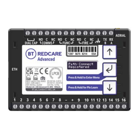
Product description
Advanced and Advanced Extra are dual path alarm signalling units for transmitting alarm signals from a
customer’s alarm panel, via the BT Redcare network, to an Alarm Receiving Centre (ARC) using pass-through
mode of operation. Both Advanced and Advanced Extra units are IP primary path with dual SIM 4G/2G
mobile technology as the backup path. The units are designed for use in both Security and Fire systems.
The unit communicates via the BT Redcare Network and a valid TA (Terminal adapter) account must exist
for the unit to communicate. The TA account will have been populated with the serial number of the unit.
Once connected to the platform the unit uses a poll and response check to determine path status. When the
primary path fails the secondary path will take up the polling and reporting parameters of the primary path.
Individual path fails are transmitted over the remaining path. Dual path failure is platform generated.
The unit has 16 general purpose alarm inputs, and 3 outputs, making it suitable for connection to most
common alarm panels. The unit is supplied already fitted with two BT Redcare enabled SIM cards, one an
EE UK fixed SIM and a UK roaming SIM. Both enabled for 4G/2G connectivity.
Advanced Advanced Extra
Primary path fail reporting 30 mins 180 secs
Secondary path fail reporting 5 hours 60 mins
Both paths fail concurrent 60 mins 6 mins
Catastrophic failure (both paths together) 31 mins 4 mins
Alarm Transmission category EN Standards / PD6669 (UK) DP2 DP3
PD6669, EN50131 (2017) Grade 3/2 3
Grade option (Table 10 EN50131-1 2020) 3C, 2F 3E
Previous grade (Pre June 1st 2019) 3 4
Environmental class II II
Information and Substitution security AES256 AES256
Introduction
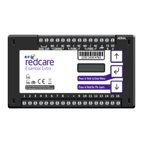
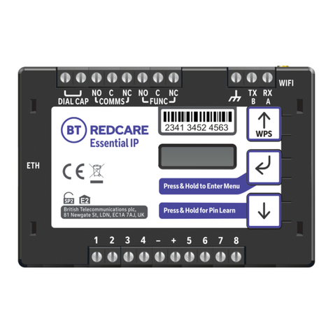
Figure 1 – Advanced and Advanced Extra unit (not to scale)
1277 3427 5899
1292 2430 4763
1292 2430 4763
Essential Essential IP Essential Extra Advanced Ultimate
1287 5675 8214
DIAL CAP
–+
COMMS
NO NCCNO NC
B
ETH
C
FUNC
C
AERIAL
0832-UKCA-CPR-X0002
2831-CPR-X0011
SEE INSTALL GUIDE
EN 50136-2:2013
EN 50131-10:2014
Cert No. 1270g
Model: UC-340 Advanced 9-30V 185mA
DIAL CAP
–+
COMMS
NO NCCNO NC
B
ETH
C
FUNC
C
AERIAL
Advanced
1287 5675 8214 ESA
1287 5675 8214 WPS
1287 5675 8214
DIAL CAP COMMS
NO NCCNO NC TX
B
C
FUNC
DIAL CAP COMMS
NO NCCNO NC RX
BA
C
FUNC
AERIAL
–+
COMMS
NO NCCNO NC
B
C
FUNC
EN 50136-2:2013
EN 50131-10:2014
Cert No. 1270
Model: UC-340 Essential 9-30V 165mA
3
