8
Outputs
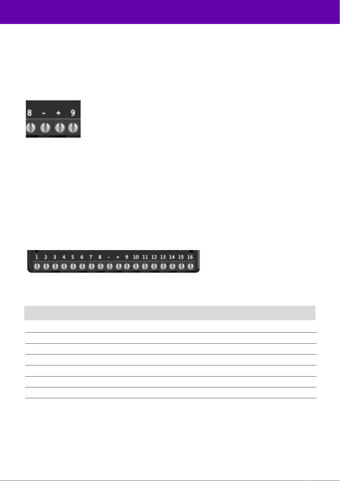
Three relay outputs are provided on screw terminals at the top of the unit.
Output 1 is Comms, Output 2 is Func, and Output 3 is Fire.
For fire alarm installations the indication of ‘acknowledgement of fire alarm’ and ‘SPT fault’ messages must be provided by
the fire panel into which the SPT is mounted. System fault indications which are notified by the line fault output
(Output 1) must be latched by the fire panel as required by EN 54-21.
See the further sections on outputs for a full explanation.
Serial data connections
The serial data connection labelled TX, RX, B and A is configurable for RS485 or RS232 connection depending on the
panel.
This is done in the configuration menu.
These ports allow serial alarm panel connection. See Panel Upload Download section.
Dial capture
The dial capture (Dial Cap) terminals enable interfacing with an alarm panel’s digital communicator. The alarm panel can
then send SIA, CID or Fast Format messages through the unit to the Alarm Receiving Centre.
Dial capture can also be used for upload download UDL allowing remote access with some types of alarm panel.
Ethernet connection
The Ethernet port needs to be connected to a suitable Ethernet network using CAT5 cable. For most IP installations,
a standard Ethernet patch cable can be used.
Aerial connection
Connect the supplied aerial to the MMCX connector on the top right of the unit. The aerial should be placed in a vertical
position that receives the best wireless coverage. Carry out a survey to establish the best location.
If necessary, a selection of high gain and extension aerials can be purchased from the BT Redcare shop at
https://www.btinstallershop.com