BTS INFINI-T P-6000 User manual

user manual
english
version 2.1.4

2
Document Number: ERP6K-01073-10
Published: September 2019
Copyright (c) 2015-2019 BTS S.p.A. All Rights Riserved.

3
Contents
Contents ............................................................................................................................................ 3
Icons, symbols and acronyms .................................................................................................................. 4
Disposal (WEEE) ................................................................................................................................... 6
Intended use ....................................................................................................................................... 7
Regulatory Label .................................................................................................................................. 8
Warning............................................................................................................................................. 9
copyright ......................................................................................................................................... 11
introduction...................................................................................................................................... 12
Use of the system............................................................................................................................... 13
BTS Digivec software ........................................................................................................................... 15
Configurations ................................................................................................................................... 20
Appendix A ....................................................................................................................................... 21
Technical features .................................................................................................................................. 21
Appendix B ....................................................................................................................................... 22
Environmental Specifications .................................................................................................................. 22
Appendix C ....................................................................................................................................... 23
Electromagnetic compatibility ................................................................................................................ 23
Appendix D ....................................................................................................................................... 23
Technical Support ................................................................................................................................... 27

4
Icons, symbols and acronyms
Symbol in the instructions for use. The icon represents the information which requires special attention.
Symbol on the equipment.
Symbol for “Manufacturer”. This symbol shall be adjacent to the name and address of the manufacturer.
Symbol on the equipment. Caution, consult the accompanying documents.
Symbol on the equipment and in the users’ instructions.
Symbol for the separate disposal of electrical and electronic equipment, in accordance with Directive 2002/96/CE
(WEEE).
The equipment belongs to Group 8 (medical equipment). In force in the nations of the European Union, Norway and
Switzerland.
Symbol on the equipment:
Type B applied part. Although the device never comes in contact with the patent (therefore it doesn’t have a proper
“applied part”), the insulation class of the device (according to IEC 60601-1) is “Class I”.
Symbol on the equipment.
Symbol located next to the model number (ref. to catalogue).
Symbol on the equipment.
Symbol located next to the serial number on the equipment.
Symbol on the equipment.
The CE mark indicates that the device satisfies the essential requirements of the Medical Devices Directive 93/42/EC.

5
Symbol for prescription only. U.S. Federal law restricts this device to sale by or on the order of a physician or properly
licensed practitioner.
Symbol on the equipment.
Symbol for the System of reference of the forces measured.
No. 5019 (IEC 60417) Protective earth (ground): To identify any terminal which is intended for connection to an
external conductor for protection against electrical shock in case of a fault, or the terminal of a protective earth
(ground) electrode.
Read operating instructions
Symbol for Voltage: 48 Vdc nominal supply voltage
37,0 Vdc – 57,0 Vdc – range

6
Disposal (WEEE)
In disposing of the equipment observe the legal prescriptions.
In accordance with Directive 2002/96/CE (WEEE) all equipment supplied after 13/08/2005 may not be
disposed of in general domestic waste. This equipment belongs to Category 8 (medical equipment) and it is
classified in the Business-to-Business sector.
The symbol of the crossed out rubbish bin indicates that the equipment must not be
disposed of in normal domestic waste.
For further information about proper disposal and recycling, please contact your local
reseller or BTS S.p.A. directly.

7
Intended use
deep analysis of a subject’s static postural condition and dynamic postural condition.
Is a force platform, which measures ground reaction forces throughout its surface, allowing a

8
Regulatory Label
The regulatory label on the force plate is:
The following label is added only for shipments to Brazil, both on the device and on the package:

9
Warning
We recommend to carry out any kind of operation keeping strictly to the security regulations
contained in this manual.
The safety of the system cannot be guaranteed if these conditions are not respected.
P-6000 is a Medical Device according to the European Directive 93/42/ EC and further amendments,
included Directive 2007/47/EC which use must always be under the supervision of qualified and certified
personnel, according to the local regulations. Federal (USA) laws restrict this device to sale by or on the
order of a physician or a properly licensed practitioner.
This device is intended to be used by healthcare professionals. This device may cause radio interferences or
may disrupt the operation of nearby equipment. It may be necessary to make mitigation measures, such as
re-orienting or re-locating the device or shielding the location.
To install the device, refer exclusively to BTS S.p.A. authorized technicians.
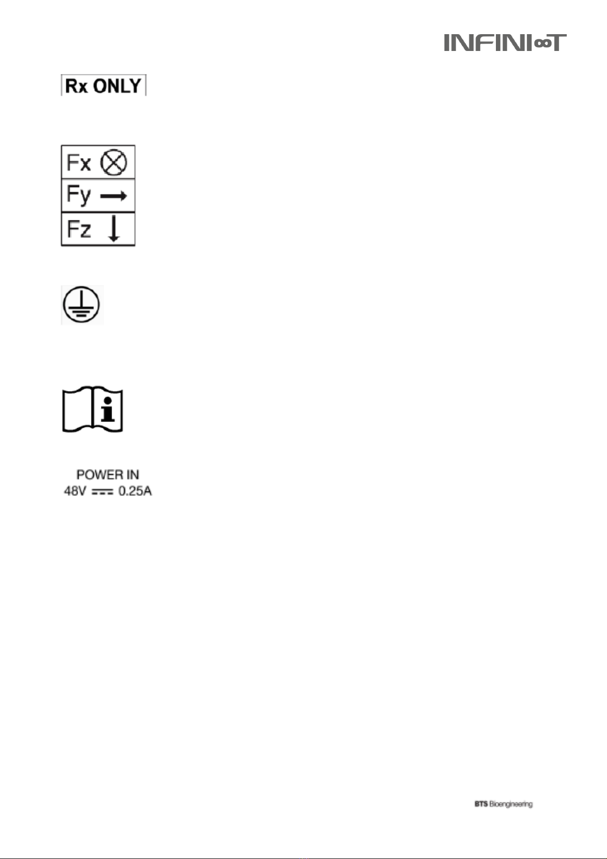
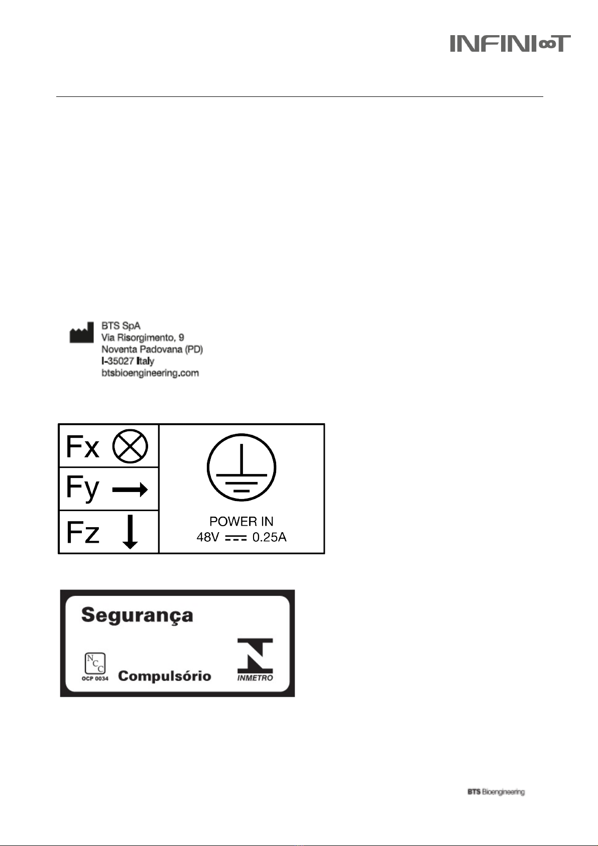
To avoid risk of electric shock, this equipment must be connected to external protective earthing system.
The results of the acquisitions must be assessed by people legally authorized by national laws, who possess
the suitable necessary knowledge of anatomy and muscular function.
Do not stand on the platform for a time exceeding 10 minutes, the platform (without mat) could reach a
temperature between 41-43°C.
The device must be used in the intended environment (see Appendix B).
The use of the device for other purposes and with methodologies different from those indicated in this
manual are not to be considered congruent with the precise use of the device.
Do not wet or dip in water the device or its parts.
Use only the power supply unit provided by BTS S.p.A. If a different power supply unit is used, the
compliance to IEC 60601-1 is not
ensured.
Only BTS S.p.A. authorized technicians may maintain and operate servicing to the system. BTS S.p.A. cannot
be held responsible for system safety should the instrument be opened, repairs carried out, third parties
software be installed, or system components be replaced by persons other than those authorized by BTS
S.p.A.
In case of accidental fall of the device, or other accident, refer to the authorized technical support.
The use of other cables and accessories, than the ones provided by BTS S.p.A., may negatively affect EMC
performance
The use of other accessories, than the ones provided by BTS S.p.A., results in non-compliance
Only original components must be used, otherwise BTS S.p.A. cannot assure the safety of the instrument. If
components other than the original ones are used the BTS S.p.A. Warranty is invalidated. Should it be
necessary to replace any part of the system, only original BTS S.p.A. parts may be used.

10
Equipment provides means to isolate its circuits electrically from the supply mains on all poles
simultaneously, through a medical power supply. Medical power supply unit is intended for disconnection
from the mains and shall be easily reachable to the user.
Means for isolation external: Medical Power Supply.
External power supply is not part of the investigation.
Warning: No modification of this equipment is allowed.
Connecting the device to a non-conforming electrical system, could damage the device, the
operator and the patent.
BTS S.p.A. cannot be held responsible for damages due to the connection of the device to a non-
conforming electrical system. The connection to an electrical system not provided with a cabin
distribution medium/law voltage (i.e. home electrical system) may cause difficulties to the electromagnetic
compatibility in other environment due to conducted and radiated disturbances.
Information contained in this manual are subject to change without notice and does not
constitute product specifications or any obligations on the part of BTS S.p.A.

11
copyright
The software of the system described in this manual is supplied with the “license of use” contract. The
software may be used or copied only as stipulated under the terms of this contract. No part of this manual
may be copied or transmitted in any form or means, electronic or mechanical, including photocopying,
without prior written permission from BTS S.p.A.
Unless otherwise specified, any reference to companies, names, data and addresses used in the
reproduction of the screens and the examples are purely incidental, and has the sole purpose of illustrating
the use of the BTS product. All trademarks are registered by the respective owners.
This publication contains reserved information which is the property of BTS S.p.A.
The recipient acknowledges that the illustrations and information supplied in this manual shall
not be made
available to third parties without explicit written agreement by BTS S.p.A.

12
introduction
This equipment is an instrument for the movement analysis, classified as medical equipment in accordance
with European Directive 93/42/EEC and further amendments.
By adding optional video cameras (up to four) it’s possible to watch and record the subject from different
angles, give a superimposed representation (augmented reality) of direction and intensity of force vectors:
knowledge about the direction of reactive force in relation to the joints allows the evaluation of functional
overload, injury prevention, the detection of possible load asymmetries, and the adoption of the most
successful rehabilitation therapy.
• Analyse load symmetry and plan medication or surgery treatments in orthopaedics;
• Perform postural evaluations and/or neurological investigations (stabilometric);
• Consider postural re-education therapy;
• Prevent injuries and enhance sports’ performance.
Components
The standard configuration includes:
The following optional components are available:
General description
Is a modular sensory floor which measures ground reaction forces throughout its surface, allowing a deep
analysis of a subject’s static postural condition and dynamic postural condition.
The subject can move freely and any contact to floor is used for the dynamic analysis of movement. This
feature makes it an essential, one of a kind tool for the diagnosis and comprehension of complex
conditions suffered by patients with severe neuro-motor dysfunctions. It can also be used for the
performance of biofeedback training for posture and for maximizing sports professionals’ athletic
performance.
Is a high performance force platform, it’s fully digital and equipped with twelve sensors (transducers) for
each platform which break force into its different components and perform an accurate, high-frequency
analysis.
Applications
Is highly recommended in order to:
• 1,2,4,8 or 16 BTS (depending on the configuration) • 1
PoE HUB each 4 force platforms
• Connection cables.
• Analog interface (optional configuration of BTS ) •
Squared model (optional dimensions 40 x 40 cm) •
Modular walkway
• BTS VIXTA video system (up to 4 video-cameras)
• BTS Digivec Software

13
Use of the system
Recommended environment
• Clean and non-slip to ensure a firm positioning of the force platform;
• Level at 2 mm;
• Minimal vibration transmitting ability. Also little vibration could disturb the measure;
• The environment of use mustn’t have a humidity degree out of the range specified in Appendix B,
The installing operations must be performed exclusively by BTS S.p.A. authorized technicians.
Each HUB PoE could be connected to a maximum of 4 force platforms. If more platforms should
be connected, be aware to use more of the provided HUB PoE and to use the provided switch to
connect the HUBs each other.
• BTS SMART-Analyzer
• BTS SMART-Clinic
• BTS SMART-Performance
Is developed for IN-DOOR applications, with a humidity range of 50-80% (see Appendix B –
environmental specifications).
The appropriate surface to positon the force platform must have a solid foundation (concrete, cement or
linoleum), with the following main characteristics:
or be subject to water infiltration near the location of the device.
For the protection against bust and water infiltration, refer to the definitions of IP codes (Ingress Protection
rating) specified in CEI EN 60529/1997 (ex CEI 70-1) which specifies the environmental protection provided
by the enclosure of electrical equipment.
The IP code assigned is IP42.
Connecting the device
Before switching on, follow the instructions below:
1. Connect each module to the PoE HUB through one of the provided LAN cables; 2.
Connect the PoE HUB to the PC, through another LAN cable;
3. Finally connect the power supply cable of the PoE HUB to the mains supply.
Now the BTS is ready to be used.
Application software
BTS could be provided with the following BTS software:
• BTS Digivec (see next Chapter) and VIXTA video cameras;
BTS has been developed to be integrated to all BTS systems for motion analysis, so it could be
acquired by all application software of
the BTS SMART-Suite and by the analysis software:

14
For the protection against bust and water infiltration, refer to the definitions of IP codes (Ingress
Protection rating) specified in CEI EN 60529/1997 (ex CEI 70-1) which specifies the environmental
protection provided by the enclosure of electrical equipment.
For updates and maintenance please refer exclusively to BTS S.p.A. support
(helpdesk@btsbioengineering.com).
Keep the original packaging to benefit the warranty conditions. BTS S.p.A. cannot be held responsible for
unauthorized or autonomous maintenance operations.
To acquire the previously listed software, refer to their specific user manuals.
System maintenance
The replacement or update of the hardware configuration will be performed exclusively by BTS S.p.A.
authorized technicians.
Should be protected by dust, humidity and water. Be careful to avoid shocks which could due to
malfunctioning of the system.

15
BTS Digivec software
The prohibition symbol indicates that it is not possible to acquire data in the present configuration.
To allow performing the acquisition is required to set the configuration and the calibration of the force
platforms in the laboratory, to align the images acquired by the cameras to the forces acquired in the
laboratory.
Platforms configuration
Select in the tool bar the item “Platforms Manager” and then the item “Platforms” in the drop-down menu:
Now the window “Platform Configuration” will be displayed. This window allows setting the spatial
configuration of the platforms in the laboratory:
Could be acquired using BTS Digivec software and VIXTA video cameras, through a few simple steps.
Connect VIXTA video cameras to the switch for LAN cables connected to the PC.
Run the Digivec program clicking the file “3Digivec.vsb”, or selecting the shortcut on your desktop.
Once run the program, the following window will be displayed, showing the images of the cameras
watching installed in the laboratory:

16
This window allows also to set the number of platforms to use and the configuration data for each of them:
• IP Address;
• Serial Number;
• Group (see paragraph “Groups”);
• Firmware version (default value =2);
Once set all mandatory data, go on with the calibration of the configuration set.
First of all, positon the configuration of the platforms according to their real positioning in the laboratory,
shifting the rectangles in the correspondent positon.
The platform marked with “0” is the platform of reference for the configuration system (one of the corner
represents the origin).
Once defined the position of the platforms, positon the 4 calibration balls (red, green, blue, yellow)
displayed in the configuration window, putting them on the ends of the platforms (it is advisable to cover
the maximum volume, putting the balls on the extreme corners of the external platforms) as shown below:
Push “Save” to save the set configuration and return to the main menu.

17
If data inserted are correct the prohibition symbol will disappear.
Platforms calibration
Select from the tool bar the icon “New Calibration”:
Position the calibration balls on the 3D image as just done on the configuration window. Be careful to
maintain the correspondence of the colors used in the configuration window.
The magenta ball should be positioned vertically aligned on the red ball, at a distance of 60 cm.
To allow an easier positioning of the magenta ball, use the calibration kit with one harm long 60
cm, provided by BTS S.p.A. (the tern should be positioned on the first corner of the platform of
reference).
This will allow the real time update of the correspondence between the virtual platforms (in blue) and the
real platforms in the video image.
The calibration should be repeated for each camera, selectable in the drop-down menu of the calibration
window:
If the balls are not visible, their positon could be reset, using the icon “Reset Calibration” ( ) in the
calibration window.
Once completed the calibration for all cameras, push the icon “Save” ( ).
Data Acquisition
The data acquisition is now allowed.
Push “REC” to start acquiring the video and TDF data of the measured forces;
Push “Stop” to end the acquisition;
Push “Save” to save the acquisition.
The “Play” button allows displaying the video with the forces applied.

18
For each acquired camera there’s a video and TDF. File containing the data related to the acquired forces.
For further information, refer to BTS Digivec software User Manual.
Groups
Through the configuration window it’s allowed to assign each platform to pre-set groups, platforms could
be assigned to the same group allowing to display the total group acquisition, selecting the option
“Show Group” in the visualization menu “View” in the toolbar.
To select the group, select the option “Manage Platform Group Color” in “Platform Configuration”:
The window “Groups Manager” allows adding, removing or modify pre-set groups. Default groups couldn’t
be deleted, but it is possible to set their color.
Default’s groups are:
• l gr: left foot’s group;
• r gr: right foot’s group;
• No Group: no group is assigned.
If platform are assigned to the same group, it is allowed to display data and forces for the same anatomical
part and to analyse its functionality and performance (i.e.: the left or right leg, for forces measured by two
platform a single force vector will be displayed, representing the result of the two forces).
The assignation to groups is allowed through the “Platform Configuration” windows and while
viewing acquired data.
Data view
From the drop-down menu “View” in the toolbar, it is possible to set all data view option:
• 3D Scheme (default option): displays the 3D acquisition environment;
• Plate visible: to display also the virtual platforms (blue color);
• Reference system visible: to display the system of reference;
• Show resultant: to display the resultant of applied forces;
• Show group: to display each group;

19
• Show force vectors: to display force’s vectors;
• Walkway: to display only the upper surface of the platforms, useful when there’s a walkway.
Forces should be superior to the minimum detection threshold of 30 N (3 kg). Lower forces are
not measured.

20
Configurations
Is a modular sensory floor, which could be composed by multiple units, placed in an ad hoc walkway to
provide the user a complete sensorized floor, configurable for different acquisition requirements.
is the squared model which differs only for dimensions which are 40 x 40 cm instead of 60 x 40 cm.
Table of contents
Other BTS Medical Equipment manuals