3
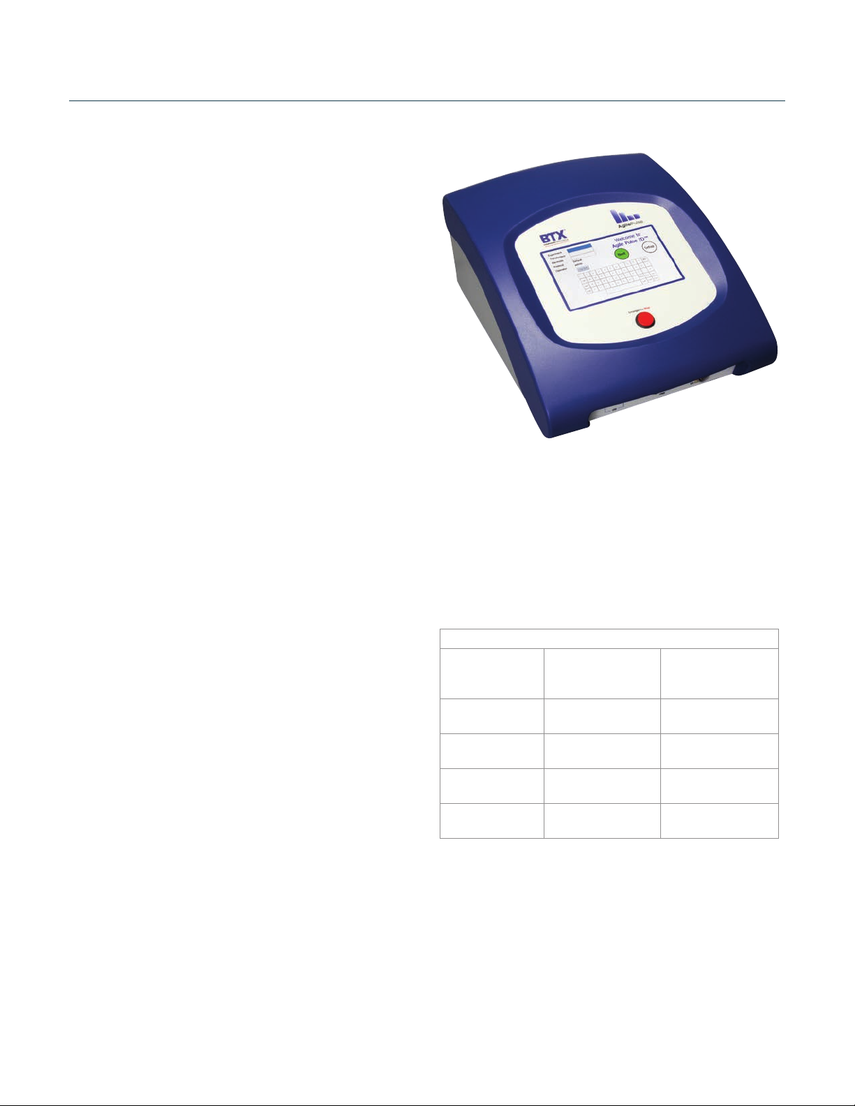
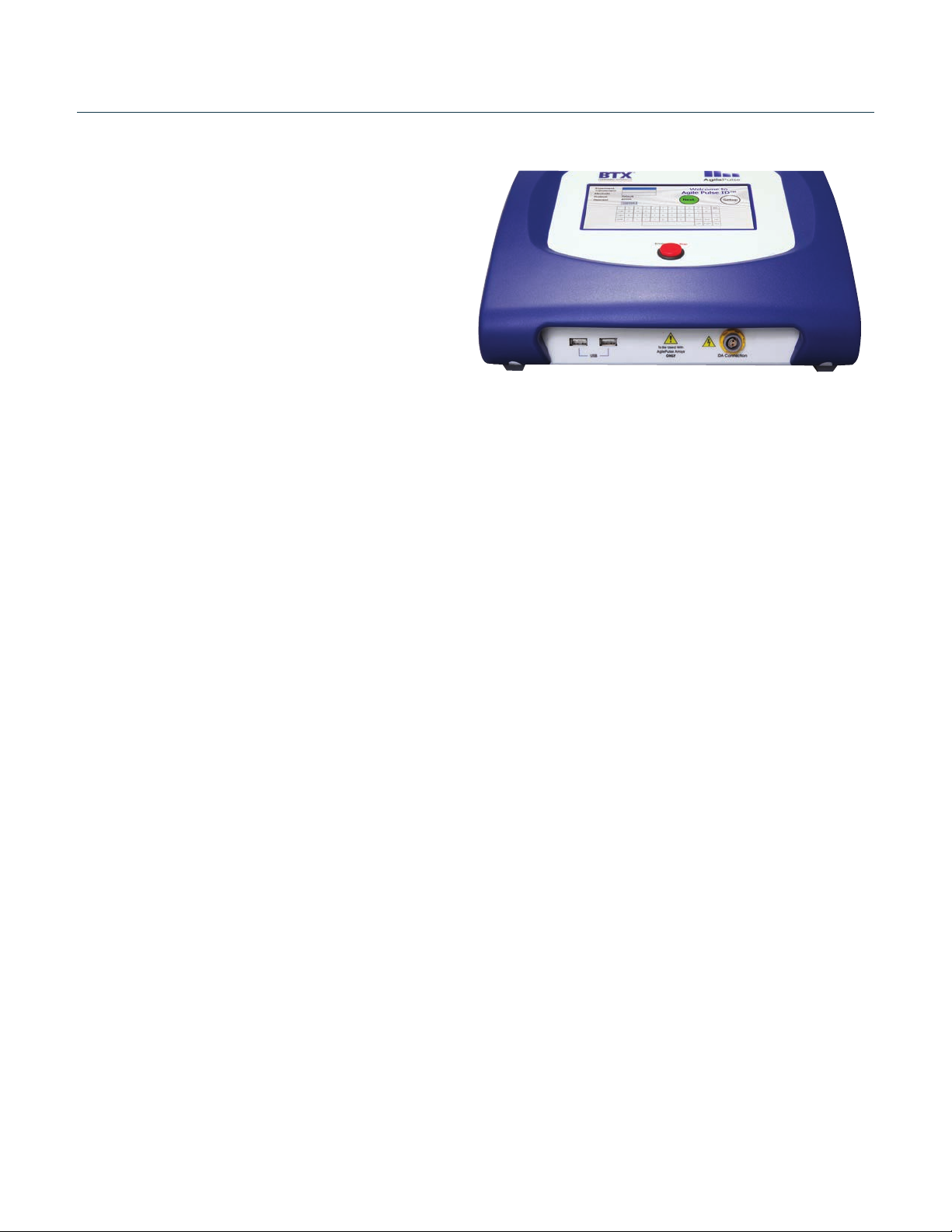
AgilePulse ID In Vivo Gene Delivery System
Publicaon 015-101444 Rev 2.0 • www.btxonline.com
Warranty Information
RESEARCH ONLY
BTX
84 October Hill Rd
Holliston, MA 01746, USA
Phone: 1-508-893-8999
Fax: 1-800-429-5732
Web: www.btxonline.com
Warranty
BTX warranes AgilePulse systems for a period of two years from
the date of purchase. At its opon, BTX will repair or replace
the product if it is found to be defecve as to workmanship or
materials. This warranty does not extend to any device which
has been (a) subjected to misuse, neglect, accident or abuse, (b)
repaired or altered by anyone other than BTX without BTX express
and prior approval, (c) used in violaon of instrucons furnished
by BTX. This warranty extends only to the original customer
purchaser. IN NO EVENT SHALL BTX BE LIABLE FOR INCIDENTAL OR
CONSEQUENTIAL DAMAGES. Some states do not allow exclusion
or limitaon of incidental or consequenal damages so the above
limitaon or exclusion may not apply to you. THERE ARE NO
IMPLIED WARRANTIES OF MERCHANTABILITY, OR FITNESS FOR
A PARTICULAR USE, OR OF ANY OTHER NATURE. Some states
do not allow this limitaon on an implied warranty, so the above
limitaon may not apply to you. Without liming the generality
of the foregoing, BTX shall not be liable for any claims of any kind
whatsoever, as to the equipment delivered or for non-delivery of
equipment, and whether or not based on negligence. Warranty
is void if the BTX AgilePulse system is changed in any way from
its original factory design or if repairs are aempted without
wrien authorizaon by BTX. Warranty is void if parts, connecons
or electrodes not manufactured by BTX are used with the BTX
AgilePulse instrument. If a defect arises within the warranty period,
promptly contact BTX, 84 October Hill Road, Building 7, Holliston,
Massachuses, USA 01746-1388 using our toll free number
1-800-272-2775 (US Only) or 508-893-8999 (E-mail: support@
hbiosci.com). Goods will not be accepted for return unless an RMA
(Returned Materials Authorizaon) number has been issued by
our customer service department. The customer is responsible
for shipping charges. Please allow a reasonable period of me
for compleon of repairs, replacement and return. If the unit is
replaced, the replacement unit is covered only for the remainder
of the original warranty period dang from the purchase of the
original device. This warranty gives you specic rights, and you may
also have other rights, which vary from state to state.
Out of Warranty Service
Proceed exactly as for Warranty Service above. If our service
department can assist you by phone or other correspondence, we
will be glad to help at no charge.
Repair service will be billed on the basis of labor and materials.
A complete statement of me spent and materials used will be
supplied. Shipment to BTX should be prepaid. Your bill will include
return shipment freight charges.
Disassembly by the user is prohibited. Service should only be
carried out by experienced BTX technicians.
Repair Facilies and Parts
BTX stocks replacement and repair parts. When ordering, please
describe parts as completely as possible, preferably using our part
numbers. If praccal, enclose a sample photo or drawing.
Cauon Noce
The BTX AgilePulse systems are intended for laboratory use only
and can be used in research and development applicaons.
These systems have been designed to meet the standards for
electromagnec compability (EMC) and safety intended for
laboratory equipment applicaons.
This product should not be used in the presence of a ammable
atmosphere such as an anesthec mixture with air, oxygen, or
nitrous oxide.