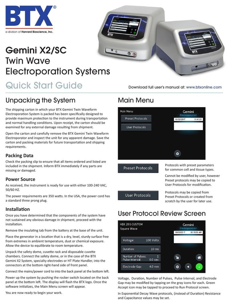
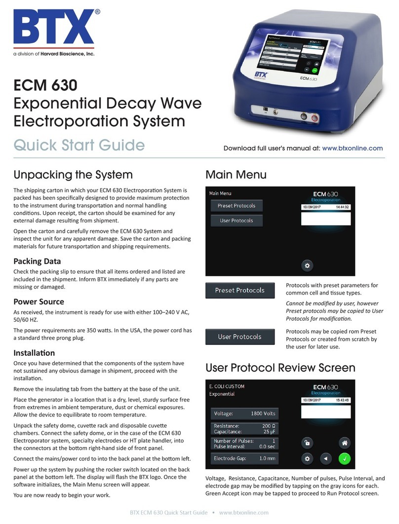
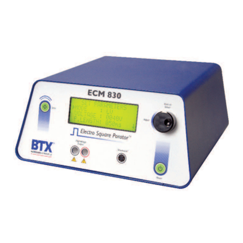
BTX ECM630 User manual

User’s Manual
ECM®630 Electroporation System
Publication 5501-003-REV-C
MA1 45-0051 ECM®630 Electroporator only (110V)
MA1 45-0051int ECM®630 Electroporator only (220V)

EU Directives WEEE and RoHS
To Our Valued Customers:
We are committed to being a good corporate citizen. As part of that commitment,
we strive to maintain an environmentally conscious manufacturing operation.
The European Union (EU) has enacted two Directives, the first on product recycling
(Waste Electrical and Electronic Equipment, WEEE) and the second limiting the use
of certain substances (Restriction on the use of Hazardous Substances, RoHS).
Over time, these Directives will be implemented in the national laws of each EU
Member State.
Once the final national regulations have been put into place, recycling will be offered
for our products which are within the scope of the WEEE Directive. Products falling
under the scope of the WEEE Directive available for sale after August 13, 2005 will
be identified with a “wheelie bin” symbol.
Two Categories of products covered by the WEEE Directive are currently exempt
from the RoHS Directive – Category 8, medical devices (with the exception of
implanted or infected products) and Category 9, monitoring and control instru-
ments. Most of our products fall into either Category 8 or 9 and are currently
exempt from the RoHS Directive. We will continue to monitor the application of the
RoHS Directive to its products and will comply with any changes as they apply.
• Do Not Dispose Product with Municipal Waste
• Special Collection/Disposal Required
WEEE/RoHS Compliance Statement

ECM®630 Electroporation System
Page 1 www.btxonline.com
Table of Contents
General Information:
Serial Number................................................................2
Calibration......................................................................2
Warranty ....................................................................2-3
Service........................................................................3-4
Repair Facilities and Parts ..............................................4
General Safety Summary..............................................5-6
Electrical & Technical Specifications ..............................7
General Specifications......................................................8
Introduction:
ECM®630 Features ......................................................9
Operation: Getting Started ............................................10
Quick Start:
Installation ....................................................................11
Connecting ..................................................................11
Initializing......................................................................11
Instrument Controls................................................12-17
Operating Basics ......................................................18-19
Advanced Operation: Programming ............................20
Electroporation ..............................................................21
Applications:
Electroporation ......................................................22-23
Appendix A: ECM®630 Electrode
Operation Ranges................................24-26
Appendix B: ECM®630 RC Time Constants............27-38
Appendix C: Optimization Strategies............................39
Appendix D: Electrical Troubleshooting........................40
Appendix E: Experimental Troubleshooting ................41
Appendix F: Glossary of Electrical Terms ....................42
Appendix G: Glossary of Biological &
Technical Terms ..................................43-44
Appendix H: Electroporation Generator
Compatibility ............................................45
Appendix I: Recommended Reading ............................46
Appendix J: Accessories and Replacement Parts ........47
Appendix K: General Care and Cleaning......................48

ECM®630 Electroporation System
Page 2 www.btxonline.com
General Information
Serial Number
The serial number for the ECM®630 is located on the rear of the
instrument case. All inquiries concerning these products should refer
to the serial numbers on the units.
Calibration
There is no calibration required for the ECM®630.
Warranty
BTX - Harvard Apparatus warranties the ECM®630 for a period of two
years from the date of purchase. At its option, BTX – Harvard
Apparatus will repair or replace the unit if it is found to be defective as
to workmanship or materials. This warranty does not extend to any
instrumentation which has been (a) subjected to misuse, neglect, acci-
dent or abuse, (b) repaired or altered by anyone other than
BTX - HARVARD APPARATUS without BTX - HARVARD APPARATUS’
express and prior approval, (c) used in violation of instructions fur-
nished by BTX - HARVARD APPARATUS. This warranty extends only
to the original customer purchaser.
IN NO EVENT SHALL BTX - HARVARD APPARATUS BE LIABLE FOR
INCIDENTAL OR CONSEQUENTIAL DAMAGES. Some states do not
allow exclusion or limitation of incidental or consequential damages so
the above limitation or exclusion may not apply to you. THERE ARE
NO IMPLIED WARRANTIES OF MERCHANTABILITY, OR FITNESS
FOR A PARTICULAR USE, OR OF ANY OTHER NATURE. Some states
do not allow this limitation on an implied warranty, so the above limi-
tation may not apply to you.
Without limiting the generality of the foregoing, BTX - HARVARD
APPARATUS shall not be liable for any claims of any kind whatsoever,
as to the equipment delivered or for non-delivery of equipment, and
whether or not based on negligence.
Warranty is void if the ECM®630 is changed in any way from its origi-
nal factory design or if repairs are attempted without written authoriza-
tion by BTX - HARVARD APPARATUS.
Warranty is void if parts, connections or cell fusion chambers not
manufactured by BTX - HARVARD APPARATUS are used with the
ECM®630.

ECM®630 Electroporation System
Page 3 www.btxonline.com
General Information (Continued)
If a defect arises within the warranty period, promptly contact BTX –
Harvard Apparatus, 84 October Hill Road, Building 7, Holliston,
Massachusetts, USA 01746-1388 using our toll free number
1-800-272-2775 (US Only) or 508-893-8999
accepted for return unless an RMA (Returned Materials Authorization)
number has been issued by our customer service department. The
customer is responsible for shipping charges. Please allow a reason-
able period of time for completion of repairs, replacement and return.
If the unit is replaced, the replacement unit is covered only for the
remainder of the original warranty period dating from the purchase of
the original device.
This warranty gives you specific rights, and you may also have other
rights, which vary from state to state.
Service
All service under the warranty will be made at the BTX - HARVARD
APPARATUS, Holliston, Massachusetts facilities or an authorized
service site. Owner will ship instrument prepaid to Holliston,
Massachusetts, USA or the service site. BTX - HARVARD APPARATUS
will return the instrument after servicing, freight prepaid to owner’s
address.
Obtaining Service:
Service During Warranty
1. Write or call the BTX - HARVARD APPARATUS Customer
Support Group and describe the nature of the problem.
2. Carry out minor adjustments or tests as suggested by
BTX - HARVARD APPARATUS.
3. If proper performance is not obtained, BTX - HARVARD
APPARATUS will notify you to ship the instrument, prepaid,
to its Service Department.The instrument will be repaired
and returned at no charge for all customers in the
continental United States.
Customers outside of the continental United States who have
purchased our equipment from distributors should contact the
distributor. If you have purchased your equipment from us, you
should contact us directly. We will repair at no charge, but will not
pay for shipment, documentation, etc. These charges will be billed
at cost.
Note: Under no condition should the instrument or accessories be
returned without prior approval from BTX - HARVARD APPARATUS. An
RMA (Returned Materials Authorization) number must be obtained.

ECM®630 Electroporation System
Page 4 www.btxonline.com
General Information (continued)
Out-Of-Warranty Service
Proceed exactly as for Warranty Service, above. If our Service
Department can assist you by phone or correspondence, we will be
glad to, at no charge.
Repair service will be billed on the basis of labor and materials. A
complete statement of time spent and materials used will be supplied.
Shipment to BTX - HARVARD APPARATUS should be prepaid. Your
bill will include return shipment freight charges.
Disassembly by the user is prohibited. Service should only be carried out
by experienced BTX - HARVARD APPARATUS technicians.
Repair Facilities and Parts
BTX - Harvard Apparatus stocks replacement and repair parts. When
ordering, please describe parts as completely as possible, preferably
using our part numbers. If practical, enclose a sample or drawing. We
offer complete reconditioning service.

ECM®630 Electroporation System
Page 5 www.btxonline.com
General Safety Summary
Review the following safety precautions to avoid injury and prevent
damage to this product or any products connected to it. To avoid
potential hazards, use this product only as specified.
Only qualified personnel should perform service procedures.
To Avoid Fire or Personal Injury
USE PROPER POWER CORD
Use only the power cord specified for this product and certified for
the country of use.
CONNECT AND DISCONNECT PROPERLY
Do not connect or disconnect probes or test leads while they are
connected to a power source.
GROUND THE PRODUCT
This product is grounded through the grounding conductor of the
power cord. To avoid electric shock, the grounding
conductor must be connected to earth ground. Before making
connections to the output terminals of the product, ensure that the
product is properly grounded.
OBSERVE ALL TERMINAL RATINGS
To avoid fire or shock hazard, observe all ratings and markings on the
product. Consult the product manual for further ratings information
before making connections to the product.
DO NOT OPERATE WITHOUT COVERS
Do not operate this product with covers or panels removed.
Use Proper Fuse. Use only the fuse type and rating specified for this
product.
AVOID EXPOSURE TO CIRCUITRY
Do not touch exposed connections and components when power is
present.
DO NOT OPERATE WITH SUSPECTED FAILURES
If you suspect there is damage to this product, have it inspected by
qualified service personnel.
PROVIDE PROPER VENTILATION
Refer to installation instructions for details on installing the product to
ensure proper ventilation.
DO NOT OPERATE IN WET/DAMP CONDITIONS
DO NOT OPERATE IN AN EXPLOSIVE ATMOSPHERE
KEEP PRODUCT SURFACES CLEAN AND DRY
Should you have any safety concerns, immediately contact BTX
Technical Services (1-800-272-2775)

ECM®630 Electroporation System
Page 6 www.btxonline.com
General Safety Summary (Continued)
Safety Terms and Symbols:
Terms that appear in this manual:
WARNING. Warning statements identify
conditions or practices that could result in injury or
loss of life.
CAUTION. Caution statements identify
conditions or practices that could result in
damage to these products or other property.
Symbols that may appear on the products:
Danger Attention Protective Functional
High Refer to (Earth) Ground
Voltage Manual Terminal

ECM®630 Electroporation System
Page 7 www.btxonline.com
Electrical & Technical Specifications
Standard Capabilities:
Display Type: 20-character by 4-line
liquid crystal Display.
LED backlit
Power Source
Voltage 100 to 240 Vac, 50 to 60 Hz,
CAT II
Power 500 W (Pulsed), 50 W (Idle)
Fusing 2.5 A, T rating 250 V
Environmental Characteristics:
Intended Use Indoor use only
Operating Temperature 10° C to + 40° C
Cooling Convection through
metal case
Relative Humidity 60%
Altitude 2,000 m (operating)
Mechanical Characteristics:
Footprint 12.5” x 12.25” x 5.5”
(W x D x H)
Weight 13.6 lbs (6.2 kg)
Controls Single rotary encoder with
integrated push button

ECM®630 Electroporation System
Page 8 www.btxonline.com
General Specifications
Certifications and Compliances
Overvoltage Category:
CAT III: Products in this Category: Distribution-level mains,
fixed installation.
CAT II: Local-level mains, applications, portable equipment.
CAT I: Signal levels in special equipment or parts of equipment,
telecommunications, electronics.
Meets requirements of Directive 89/336/EEC for Electromagnetic
Compatibility (EC) and Low-Voltage Directive 73/23/EEC for
Product Safety.
Compliance was demonstrated to the following specifications as
listed in the Official Journal of the European Communities:
EN 50081-1 Emissions
EN 55011 Class B Radiated and Conducted Emissions
EN 55082-1 Immunity
IEC 10004-2 Electrostatic Discharge Immunity
IEC 10004-3 RF Electromagnetic Field Immunity
IEC 10004-4 Electrical Fast Transient/Burst Immunity
Low Voltage Directive 73/23/EEC

ECM®630 Electroporation System
Page 9 www.btxonline.com
Introduction
The ECM®630 is a new state of the art exponential decay wave elec-
troporation system designed for in vitro and in vivo electroporation
applications. This system incorporates features that make it the most
technically advanced exponential decay electroporation system
currrently available.
ECM®630 features include:
• The generator utilizes the new BTX Power Platform
Technology design and novel digital user interface.
• The revolutionary Precision Pulse™System provides the
researcher unparalleled power in controlling the time
constant.
• With the ability to deliver a maximum of 6000 A in the Low
Voltage Mode, the ECM®630 is the most powerful
generator in its class.
• Voltage range of 10 V to 500 V with 1 V resolution and
1 µF, 25 µF to 3275 µF in 25 µF increments. 25 Ωto
1575 Ω, 25 Ωresolution with “none” setting.
•Voltage range of 50 V to 2500 V with 5 V resolution
and either 25 µF or 50 µF. 25 Ωto 1575 Ωwith 25 Ω
resolution.
•Over 200 ECM®600 protocols may be duplicated with
this instrument.
• The additional ECM®630 resistor selection “none” will allow
researchers to reproduce protocols from competitive
systems lacking resistor settings or reporting “unlimited”
resistance.
• The ECM®630 will perform the widest range of
electroporation applications among commercially available
electroporation generators.

ECM®630 Electroporation System
Page 10 www.btxonline.com
Operation: Getting Started
Carefully open the box containing the ECM®630 Electroporation
System. Verify receipt of the following items:
ECM®630 Pulse Generator (1)
Power Cord (1)
Model 630E Electronic Manual (1)
BTX Electroporation Systems may be customized with the addition
of various electrodes and accessories. The following items com-
plete a typical system order:
Model 630B Electroporation Safety Stand (1)
Model 660 Cuvette Rack (1)
Model 610 BTX Cuvettes Plus (10)
Model 620 BTX Cuvettes Plus (10)
Model 640 BTX Cuvettes Plus (10)
If you have ordered alternative or different items, please verify
their receipt.

ECM®630 Electroporation System
Page 11 www.btxonline.com
Quick Start
Installation
1. Install on a bench or work table.
2. Allow a 1 to 2 inch clearance for proper cooling. It is normal
for the instrument to be slightly warmer than its’ operating
environment.
3. Choose an outlet that is readily accessible.
Connecting
1. Insert female end of power cord into male power interface
on the back panel of the ECM®630.
2. Plug male end of power cord into appropriate electrical
outlet.
3. Insert male banana plugs of the 630 B Safety Stand or
alternative electrode device into High Voltage output located
on front panel of the ECM®630.
Initializing
1. Push the power switch located on the front panel of the
ECM®630.
2. The ECM®630 will go through a series of self-test
algorithms to test generator functionality.
3. The display will flash:
4. Following this initialization screen, the first time the
instrument is initialized, the factory default display will
then read:
5. The first page of the Set Parameter Screen from the
last time the ECM®630 was used will be displayed
each time the ECM®630 is powered up after this initial
start up.

ECM®630 Electroporation System
Page 12 www.btxonline.com
Quick Start (Continued)
Instrument Controls
Power Switch
1. Electronic Power Switch located on the lower right
front panel.
2. Press once to initialize the ECM®630 and once more
to turn off.
CAUTION: A stabilization period of 3 seconds
is required after connecting to an outlet.
Pulse Switch
1. The electronic Pulse Switch on the upper left front panel is
activated in the “ready” mode when the Set Parameters
screen is displayed.
2. Once the start switch is activated, the generator will
charge the capacitors to the preset voltage, then
automatically deliver the pulse.
3. The maximum charge time is line voltage dependent
and will typically be less than 10 seconds.
4. A pulse sequence may be aborted by pressing the Pulse
switch a second time, before the charging is completed.
5. Following the delivery of a pulse, the Pulse switch can
be pressed once to leave the feedback mode and return
to the “ready” mode.
Display High Voltage
Output
Power
Switch
Parameter
Control Knob
Pulse
Switch

ECM®630 Electroporation System
Page 13 www.btxonline.com
Quick Start (Continued)
Parameter Control Knob
The Parameter Control Knob is a rotary encoder controlling both the
parameter under control and the value of the parameter under control.
1. The display will indicate which parameter is under control by
the presence of an arrow to the left of the parameter.
2. To select a parameter to adjust, rotate the knob until the
arrow is to the left of the desired parameter, then push to
select. The arrow will move to the right of the value displayed
for that parameter.
3. To adjust the value of a parameter under control, rotate the
knob clockwise to increase the value and counter clockwise
to decrease it. Once values are adjusted, push the knob to
lock settings and arrow will return to left of parameters
under control.
4. In order to move between screens, move the cursor to the
bottom of the screen and rotate the knob clockwise to move
to the next screen.
5. In order to move to the previous screen, move the cursor to
the top of the screen and rotate the knob counterclockwise.
Display
The ECM®630 Display will show two possible screens, the Set
Parameter Screen and the Pulse Delivered screen as well as various
Status Messages.
Set Parameter Screen
1. The Set Parameters screen consists of two pages showing
“Set Parameters” on the first line of each page.
2. The Voltage, Resistor (Resistance), and Capacitor
(Capacitance) are shown on the first page and the Advanced
Features including Save, View and Load are shown on the
second page of the Set Parameters screen.
3. The ECM®630 will beep when toggling from one page
to another.
Voltage
1. Voltage indicates the set voltage in volts.
2. The low voltage mode range is 10 V to 500 V in 1V
increments and the high voltage mode range is
50 V to 2500 V in 5 V increments.
3. The mode is indicated by either LV for low voltage or HV for
high voltage after the voltage value.
4. A beep is heard when transitioning between LV and HV modes..

ECM®630 Electroporation System
Page 14 www.btxonline.com
Quick Start (Continued)
Resistor
1. Resistor indicates the set resistance in Ω.
2. The resistance range is 25 Ωto 1575 Ωin 25 Ω
increments.
3. In the LV mode there is an additional resistor selection of
“None”. This indicates that there is no timing resistor in the
pulsing circuit, thus mimicking settings for competitive
electroporators in which there is either no resistor to select,
or the resistance is termed “unlimited.”
Capacitor
1. Capacitor indicates the set capacitance in microfarads (µF).
2. In the LV mode the capacitance range is 1µF,
25 to 3275 µF in 25 µF increments.
3. In the HV mode the capacitance choice is 25 µF and 50 µF.
4. The capacitance and resistance control the time constant.
Please refer to Appendix B for explanation and time
constant charts.
Advanced Features
1. The second Set Parameters screen enables the user to save,
view, and load up to three programs. Please note that
current parameters will be overwritten once a program is
loaded.
2. A default program is used to initialize the system. Program 1
is used to automatically store changes in parameters set
each time the system is pulsed.
3. Programs #2 and #3 can be used to set and save
experimental parameters for instantaneous use.
Save
1. To save the current set parameters as a program, push the
parameter control knob to move the arrow to the left of the
program number.
2. Rotate the knob to designate the appropriate program
number, then push and hold the knob in, releasing after a
confirmation screen is displayed.
3. The confirmation screen will read “Saved Current Parameters
to Set N”(where N is a number from 1 to 3).
4. Push the parameter control knob again to return to the
Set Parameters screen.

ECM®630 Electroporation System
Page 15 www.btxonline.com
Quick Start (Continued)
View
1. To view the appropriate program parameters, push the
parameter control knob to move the arrow to the left of the
program number.
2. Select the appropriate program number by rotating the
parameter control knob, then hold the knob in, releasing
after a new screen is displayed.
3. The new screen will display the parameters currently stored
under that program number.
4. Push the parameter control knob again to return to the
Set Parameters screen.
Load
1. To load a saved program, push the parameter control knob
to move the arrow to the left of the program number. Please
note that in addition to three available programs, there is
also the default program as outlined in the “Initializing”
section.
2. Rotate the knob to change the program number.
3. Push and hold the knob in, releasing after a confirmation
screen is displayed. The confirmation screen will read
“Loaded Set N to Current Parameters” (where N is a number
from 1 to 3).
4. Push the parameter control knob again to return to the
Set Parameters screen.
On-Line Help
1. In the Set Parameter Mode, an On-Line Help function is
available. On-Line Help provides a definition for all set
parameters and advanced functions.
2. To use On-Line Help, rotate the parameter control knob so
that the arrow is to the left of the parameter or feature of
interest (not the value of the parameter).
3. Push the parameter control knob in and hold until the
definition is displayed.
4. Push a second time to return to the Set Parameters screen.
Mode
Low voltage or high voltage range mode (display only, this function is
controlled by the voltage parameter)
Voltage
Peak amplitude of the output pulse

ECM®630 Electroporation System
Page 16 www.btxonline.com
Quick Start (Continued)
Capacitor
The value of the timing capacitance. Time constant t=RC
Resistor
The value of the timing resistance. Time constant t=RC
Save
Save current setup parameters to nonvolatile memory
View
Show the setup parameters stored in nonvolatile memory
Load
Load setup parameters from memory to use
Status Messages
Following the initiation of a pulsing sequence, various status messages
are displayed. The following status messages may be observed:
Charging, Pulsing, and Pulse Aborted During Charging.
Charging
As soon as the start switch is pressed, the “Charging” status message
is displayed. The capacitors in the ECM®630 are charged during the
duration of this message.
Pulsing
1.Once the capacitors have reached the preset voltage level,
they are discharged and the “Pulsing” status message is
displayed for the duration of the pulse.
2. A click or a beep will be heard during the delivery of the
pulse. The sound that is heard is a function of the pulse
length. At pulse lengths less than 1 to 2 ms, clicks will likely
be heard. At pulse lengths at or above 1 to 2 ms beeps
should be heard.
3. Following the pulsing status message, the Pulse Delivered
Screen is displayed.
4. Press the encoder or the Pulse switch to return to Set
Parameters screen.
Pulsing Aborted During Charging
1. If the start switch is activated a second time prior to delivery
of a pulse, the pulsing sequence is aborted and the “Pulsing
Aborted” status message is displayed.
2. Press the encoder or the pulse switch once to get back to
the Set Parameters screen.

ECM®630 Electroporation System
Page 17 www.btxonline.com
Quick Start (Continued)
Pulse Delivered Screen
1. The Pulse Delivered Screen is displayed following the
delivery of a pulse and is indicated by the display “Pulse
Delivered” on the top line of the screen.
2. Press the knob to return to the Set Parameters Screen.
3. The Pulse Delivered screen displays the monitored peak
Voltage and Time Constant on page 1 and the programmed
Resistance and Capacitance on page 2. Please note that a
pulse will be delivered and monitored, even if there is no
output, so do not use this feature to verify that a pulse was
delivered to your sample.
4. Always verify that your sample is connected to the
HV output.
Voltage
1. Voltage indicates the peak voltage delivered. The voltage
delivered is affected by the external load. (Sample)
2. Using heavy loads (low resistivity) will result in a slightly
lower delivered voltage. This effect is normal and will be
more pronounced with small capacitor settings.
Time Constant
Time Constant indicates the exponential decay time constant 1/e in
ms, ms, or s.

ECM®630 Electroporation System
Page 18 www.btxonline.com
Operating Basics
Use with Safety Stand 630B and BTX Disposable
Electroporation Cuvettes Plus
1. Insert the safety stand banana plugs into the HV Output on
the front panel of the ECM®630.
2. Adjust the distance between the metal contacts using the
black roller for your cuvette. (See: 630 B instruction sheet)
3. Press the green power switch to initialize the ECM®630.
4. Rotate parameter control knob to move arrow to voltage and
push to select. Rotate knob to adjust voltage. Push again to
select that voltage.
5. Rotate parameter control knob to move arrow to Resistor
and push to select. Rotate knob to adjust resistance. Push
again to select that resistance.
6. Rotate parameter control knob to move arrow to Capacitor
and push to select. Rotate knob to adjust the capacitance.
Push again to select that capacitance.
7. Prepare sample, pipette into the appropriate BTX Disposable
Cuvettes Plus, place the cuvette in the 630B Safety Stand
and secure the safety cover.
8. Press the Start button. The ECM®630 will charge and then
deliver the electroporation pulse, while beeping.
9. Process sample. Do not forget to record appropriate
parameters as displayed on the Pulse Delivered screens,
for documentation purposes.
10. To return to “ready” mode, press the Pulse button.
11. To abort a pulse before delivery, press the Pulse button
during the “charging” mode.
Use with Alternative Electrode Chambers and Applications
The ECM®630 may be used to power all BTX electroporation cuvettes
and electrodes. Follow the above instructions in conjunction with
instructions provided for the specific electrode. Refer to Appendix A
for graphical representation of operating ranges of various chambers
and applicators with the ECM®630.
Reproducing ECM 600 Protocols
The ECM®630 will reproduce all ECM®600 protocols:
1. Set the voltage as outlined in the ECM®600 protocol.
2. Calculate the RC time constant without factoring in the
external load by multiplying the ECM®600 protocol
resistance and capacitance values and dividing by 1000
to give a result in msec.
630B
MA1 45-0207
Other manuals for ECM630
2
Table of contents
Other BTX Laboratory Equipment manuals
Popular Laboratory Equipment manuals by other brands

Renfert
Renfert Catalyser 2300-0001 instruction manual

Lifecanvas Technologies
Lifecanvas Technologies SmartBatch+ user manual

Heidolph
Heidolph Multifarious Hei-SHAKE Unimax 1010 operating instructions

Biotechne
Biotechne ProteinSimple Milo installation guide

Oxford
Oxford Benchmate 54P-D manual

ASL INTERCOM
ASL INTERCOM 130 instruction manual