Buckeye X80 Activator User manual

X80 Activator
User's Manual
Version 1.2
www.buckeyecam.com

Table of Contents
1. Warnings.................................................................................................................................................... 3
2. Overview.................................................................................................................................................... 4
3. Getting Started........................................................................................................................................... 5
4. Using the Activate Button........................................................................................................................... 7
5. Wiring.........................................................................................................................................................
6. Specifications............................................................................................................................................ 11
7. Additional Information...............................................................................................................................12
. Warranty and Service............................................................................................................................... 13
X 0 Activator User's Manual v1.2 2

1. Warnings
1. Warnings
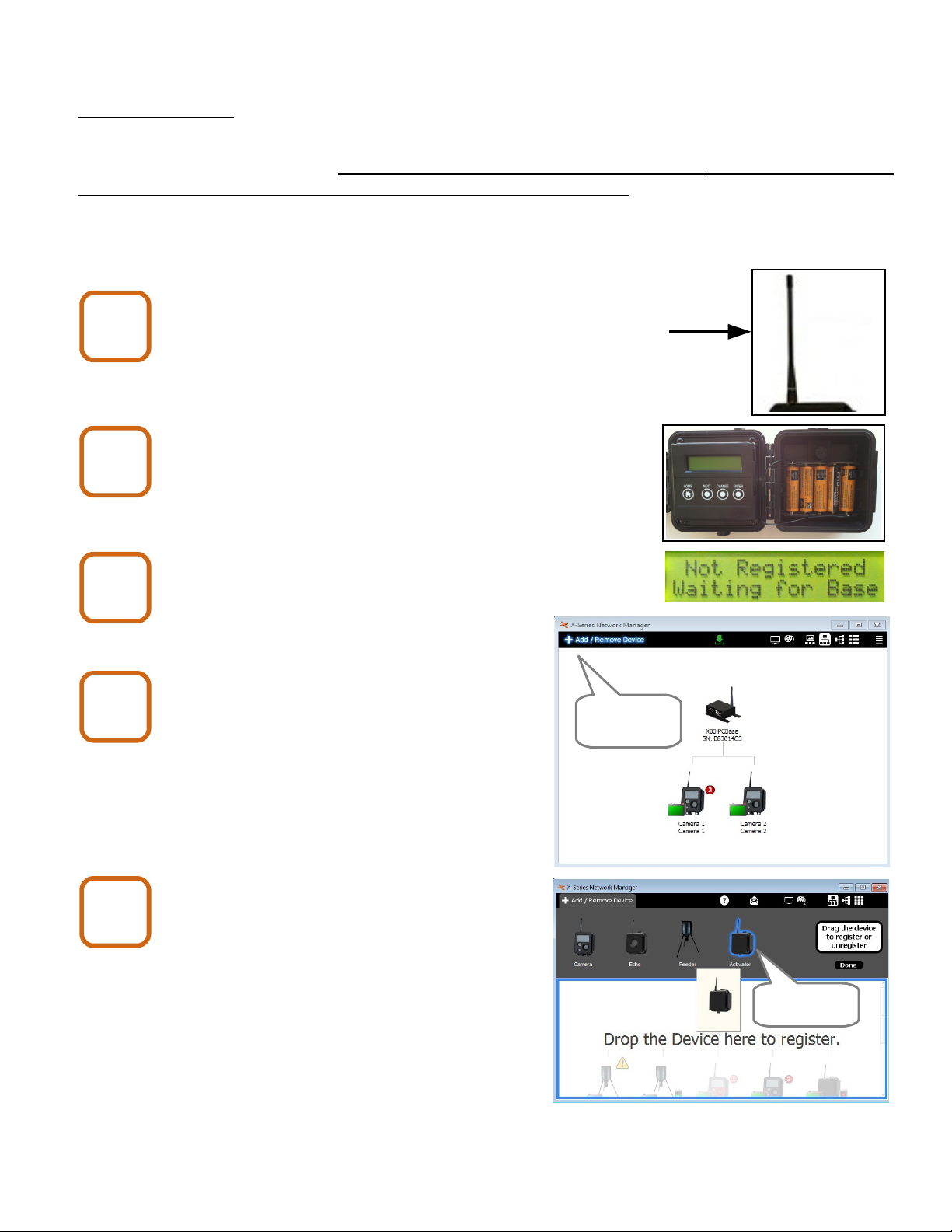
If the X80 Activator is used to remotely operate an electrical or electromechanical
device, it is the responsibility of the user to ensure that such devices are operated in
a safe manner and to ensure that any necessary safety interlocks or warning signs
are in place.
Under certain circumstances, the X80 Activator may fail to operate properly, or may
operate at random times. It should never be considered a “fail-safe” device and
should never be used in an application where a failure to operate properly may result
in a risk of personal injury or loss of life.
Contains FCC ID:MCQ-XBEE09P The enclosed device complies with Part 15 of the
FCC Rules. Operation is subject to the following two conditions: (i.) this device may
not cause harmful interference and (ii.) this device must accept any interference
received, including interference that may cause undesired operation.
If the device is used with any antenna other than the one supplied, the system may
not comply with the FCC regulation Part 15.247, Operation within the license-free
band 902 – 92 MHz. Contact manufacturer regarding use of optional high-gain
antennas with the X Series wireless camera system.
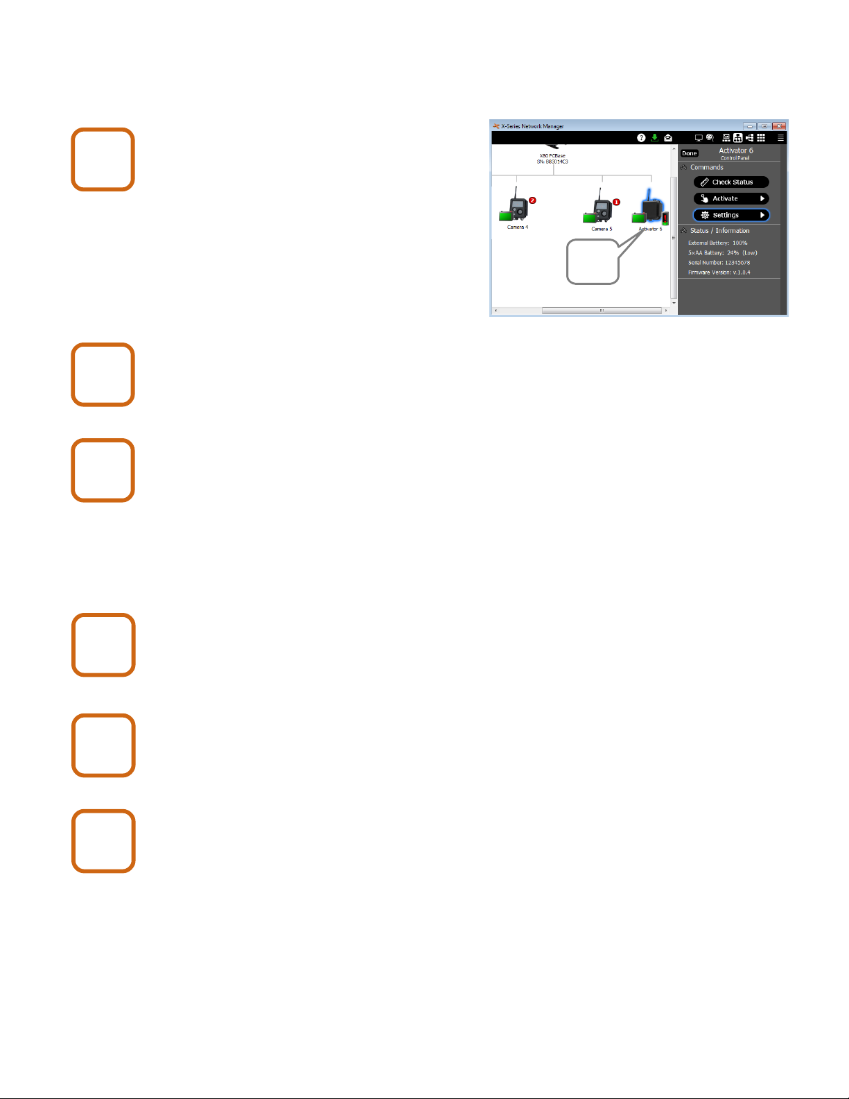
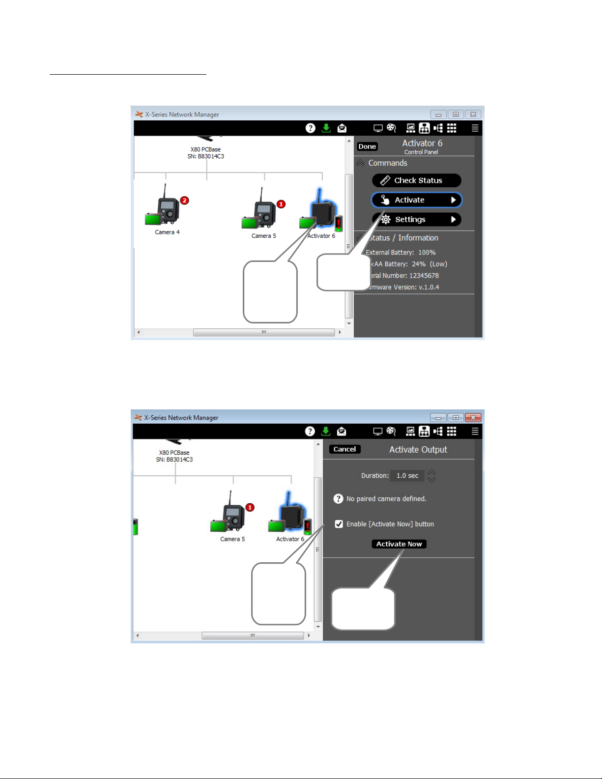
To satisfy FCC RF exposure requirements for mobile transmitting devices, a
separation distance of 20 cm or more should be maintained between the antenna of
this device and persons during device operation. To ensure compliance, operations
at closer than this distance are not recommended. The antenna used for this
transmitter must not be co-located in conjunction with any other antenna or
transmitter.
X 0 Activator User's Manual v1.2 3

2. Overview
2. Overview
The X 0 Activator can be used to remotely operate a 12 Volt DC electrical device using the X-
Series Network Manager software application. Common applications include operating gates in
response to images that are received from X80 Wireless Cameras.
Before using the X80 Activator, it is important to be familiar with X-Series Network Manager.
User's manuals and video tutorials may be found at www.buckeyecam.com/site/support.html.
X 0 Activator User's Manual v1.2 4

3. Getting Started
3. Getting Started
Before using an X80 Activator, it must be registered to a base using the X-Series Network
Manager software application. If you have not already done so, refer to the X80 Wireless Camera
System User's Manual for instructions on how to connect to a base.
If X-Series Network Manager is installed and connected to a base, follow the steps shown below to
register an X80 Activator.
Atta h antenna.
Screw the antenna onto the threaded antenna connector.
Do not over-tighten.
Install 5 AA batteries.
Remove the battery cover and install 5 AA batteries as
shown. Replace the battery cover when done.
Wait for the LCD display to read “Not Registered
Waiting for Base”.
Add to X-Series Network Manager.
Click on “Add/Remove Device”.
Cli k on the A tivator i on and drag it
into the network view.
Once the Activator has been
registered, it will be assigned a number.
X 0 Activator User's Manual v1.2 5
1
2
3
Click here
4
5
Click here

3. Getting Started
Cli k on the A tivator i on in the
network view to open the Control
Panel.
Cli k the “Settings” button on the
Control Panel.
Enter optional text labels.
Text may be entered in the Text 1 and Text 2
fields to make it easy to identify the Activator in
the software. This is especially helpful if you
have more than one Activator.
Set “Beep Before A tivation to Yes or No.
Cli k Update to save the hanges, or Can el if no
hanges were made.
Repeat steps 1 through 11 for all A tivators.
X 0 Activator User's Manual v1.2 6
6
7
8
9
10
11
Click
here

. Using the Activate Button
4. Using the A tivate Button
To access the Activate button, click on the Activator icon to open the control panel.
Set the time duration. This will limit the amount of time that the output is on.
Check the box to enable the “Activate Now” button.
Click “Activate Now” to turn the output on.
X 0 Activator User's Manual v1.2 7
Click to
open
Control
Panel
Click
Activate
Enable
the
button Turn on
the output

5. Wiring
5. Wiring
There are 3 different ways to connect the X 0 Activator to a device. In order to determine the type
of connection that is appropriate, you must know the voltage and current requirements of the
device. Three different device types are acceptable:
1. Devices that require 12 Volts and less than 5 Amps of current.
2. Devices that require 12 Volts and 5 to 20 Amps of current.
3. Devices that require a contact closure only with no voltage applied (i.e. “dry contact”).
Note: Types 2 and 3 require the optional Auxiliary Relay Pack.
For Devi es that Operate on 12 Volts and Less Than 5 Amps
Wire Color Connection Description
Red 12 Volt Battery (+) Connect to a 12 Volt battery positive terminal (+)
Black Battery (-) Connect to a 12 Volt battery negative terminal (-)
Brown Device to be activated
(+)
When activated, this wire will be switched to the (+) battery
voltage for up to 10 seconds (software adjustable setting).
Blue Device to be activated
(-)
When activated, this wire will be switched to the (-) battery.
X 0 Activator User's Manual v1.2

5. Wiring
For Devi es that Operate on 12 Volts and 5 to 20 Amps
Wire Color Connection Description
Red +12 Volts +12 Volts from battery that is inside of Auxiliary Relay Pack
Black -12 Volts -12 Volts from battery that is inside of Auxiliary Relay Pack
Brown Relay contact One side of the Normally Open relay
Blue Relay contact One side of the Normally Open relay
1. Install a UB1270 Sealed Lead Acid battery inside of the Auxiliary Relay Pack.
2. Connect the cables as shown below.
3. Connect the Red and Blue wires with supplied wire nut as shown below.
4. Connect the Brown wire to the device positive terminal (+).
5. Connect the Black wire to the device negative terminal (-).
X 0 Activator User's Manual v1.2 9

5. Wiring
For Devi es that Require a Conta t Closure to Operate
Wire Color Connection Description
Red +12 Volts Not used
Black -12 Volts Not used
Brown Relay contact One side of the Normally Open relay
Blue Relay contact One side of the Normally Open relay
1. Install a UB1270 Sealed Lead Acid battery inside of the Auxiliary Relay Pack.
2. Connect the cables as shown below.
3. Connect Blue and Brown wires to the device contact closure input.
4. The Red and Black wires are not used. Cap them off with wire nuts as shown.
Note: The Blue and Brown wires are connected to the contacts of a Normally Open relay inside of
the Relay Pack. The contacts will close when activated for up to 10 seconds (software selectable).
There is no voltage applied to the contacts (i.e. “dry contact”).
X 0 Activator User's Manual v1.2 10

6. Specifications
6. Spe ifi ations
X80 Activator Performance Features
Function 12 Volt DC output. On duration adjustable up to 10 seconds.
Compatibility All X 0 Wireless Devices, X-Series Network Manager
X 0 PC Base, Cell Base, and Net Base 1
Operating temperature -40 to 140 F
Electrical Specifications
Output 12 Volts. 5 Amps max.2 On time = 10 seconds max.
Internal battery 5 AA 3
External battery 12V SLA 3
Supply Current (Activator Only)
(Typical)6
0.5 mA when in low power sleep mode (i.e. no activity)
60 mA when transmitting
20 mA during 20 second idle state after transmission
Wireless Network
Maximum number of network devices 254 (total of all device types)
Line-of-sight transmission range Up to 2 miles with standard antennas 4
Maximum allowable antenna gain 15.1 dBi (including cable losses)
Transmission type 902 to 92 MHz frequency band, FHSS
Transmitter output power Up to 250 mW
Agency Approvals
FCC (USA) MCQ-XB900HP
IC (Canada) 1 46A-XB900HP
C-Tick (Australia) Yes
Anatel (Brazil) Pending
Dimensions
X 0 Wireless Feeder Controller 4L x 4.4W x 2.75D (Dimensions are in inches)
1 An X 0 Base is required to use the wireless features (PC Base, Cell Base or Net Base) (sold separately).
2 For currents greater than 5 Amps or for a dry contact output, the Auxiliary Relay Pack is required.
3 Batteries are not included.
4 Transmission distance depends on terrain and may be increased using high gain antennas and/or repeaters.
6 Average supply current does not include the device that is activated (i.e. solenoid, relay, etc.) and will vary depending
on level of activity, signal strength, etc..
The uckeye Cam X80 Series includes wireless cameras, sensors, repeaters, and actuators. All
of the available devices work seamlessly together and may be controlled and monitored with the
X-Series Network Manager software application.
For more information visit, www.bu keye am. om or all toll free at: 866-325-8172
X 0 Activator User's Manual v1.2 11

7. Additional Information
Video Tutorials
X-Series Network Manager video tutorials are available at
www.buckeyecam.com
.
Repeaters and High Gain Antenna Setups
For more information on the different types of repeater setups and high gain antenna options see
the X80 Wireless Camera System User's Manual available at www.buckeyecam.com.
X 0 Activator User's Manual v1.2 12

8. Warranty and Service
8. Warranty and Servi e
For service or repair, contact ATSI/Buckeye Cam at:
ATSI
157 US Hwy 50 • Athens, OH 45701
( 66) 325- 172 • (740) 592-2 74
Fax (740) 594-2 75
www.buckeyecam.com
Athens Technical Specialists, Inc. (ATSI) warrants Products (BuckEye CamTM ) sold by it and
guarantees to correct, by repair or replacement at our option, any defects of material and
workmanship which develop under normal and proper use within six (6) months from the date of
the original purchase when inspection proves the fault to be of manufacturing. Circuit board
components only receive a twelve (12) month warranty. All such Products must be returned to our
service center, transportation charges prepaid. This warranty does not apply to any of our Products
which have been repaired or altered by unauthorized persons or service centers in any way so as,
in our judgment, to injure their stability or reliability, or which have been subject to misuse,
negligence, or accident or which have had their serial number altered, effaced or removed.
We will not assume any expense or liability for repairs made by other parties without our written
consent. ATSI is not responsible for damage to any associated equipment or apparatus, nor shall
we be held liable for loss of profit or other special damages. There is no other guarantee or
warranty except as herein stated. The Buyer, his employees, or others assumes all risks and
liabilities for the operation, the use and the misuse of the product described herein and agree to
defend and to save the seller harmless from any and all claims arising from any cause whatsoever,
including seller’s negligence for personal injury incurred in connection with the use of the said
product.
ATSI reserves the right to discontinue models at any time or change specifications, price or design
without notice and without incurring any obligation. The express warranties are in lieu of all other
warranties, guarantees, promises, affirmations, or representations, express or implied which would
be deemed applicable to the goods sold hereunder. No express warranties and no implied
warranties, whether of merchantability, fitness for any particular use or purpose, against
infringement, or otherwise (except as to title) other than those expressly set forth herein, shall
apply.
X 0 Activator User's Manual v1.2 13
Other manuals for X80 Activator
1
Table of contents
Popular Gate Opener manuals by other brands

Chamberlain
Chamberlain LMWEKITU manual

Elite access systems
Elite access systems SL-3000-UL Series instruction manual

GTO
GTO SL-5100 installation manual

PPA
PPA Eurus Custom Technician guide

Relcross Door Controls
Relcross Door Controls 9130 installation instructions

Nice
Nice TOO3000 User & installation manual