Installation Manual Concentric Horizontal Vent Kit | 5
Bosch Thermotechnology Corp. Data subject to change
DANGER : Danger from escaping flue gases
Ensure all vent pipes and chimneys are not
damaged or blocked.
Connect only one appliance to each vent system
or chimney liner.
The venting system piping must not feed into
another air exhaust duct.
Do not route the flue system piping through or
inside another air exhaust duct.
WARNING: Combustion air
Keep the combustion air free of corrosive
substances (halogenated hydrocarbons that
contain chlorine or fluorine compounds).
WARNING: Maintenance
Customers are required to:
Sign a maintenance and inspection contract with
an authorized contractor. Inspect and maintain
the gas appliance on a yearly basis or more
frequently if required. Service as needed.
Use only genuine spare parts.
DANGER: Fatal accidents!
Carbon monoxide poisoning.
Carefully plan where you install the gas appliance.
Correct combustion air supply and flue pipe
installation are very important. If a gas appliance
is not installed correctly, fatal accidents can
result such as carbon monoxide poisoning or fire.
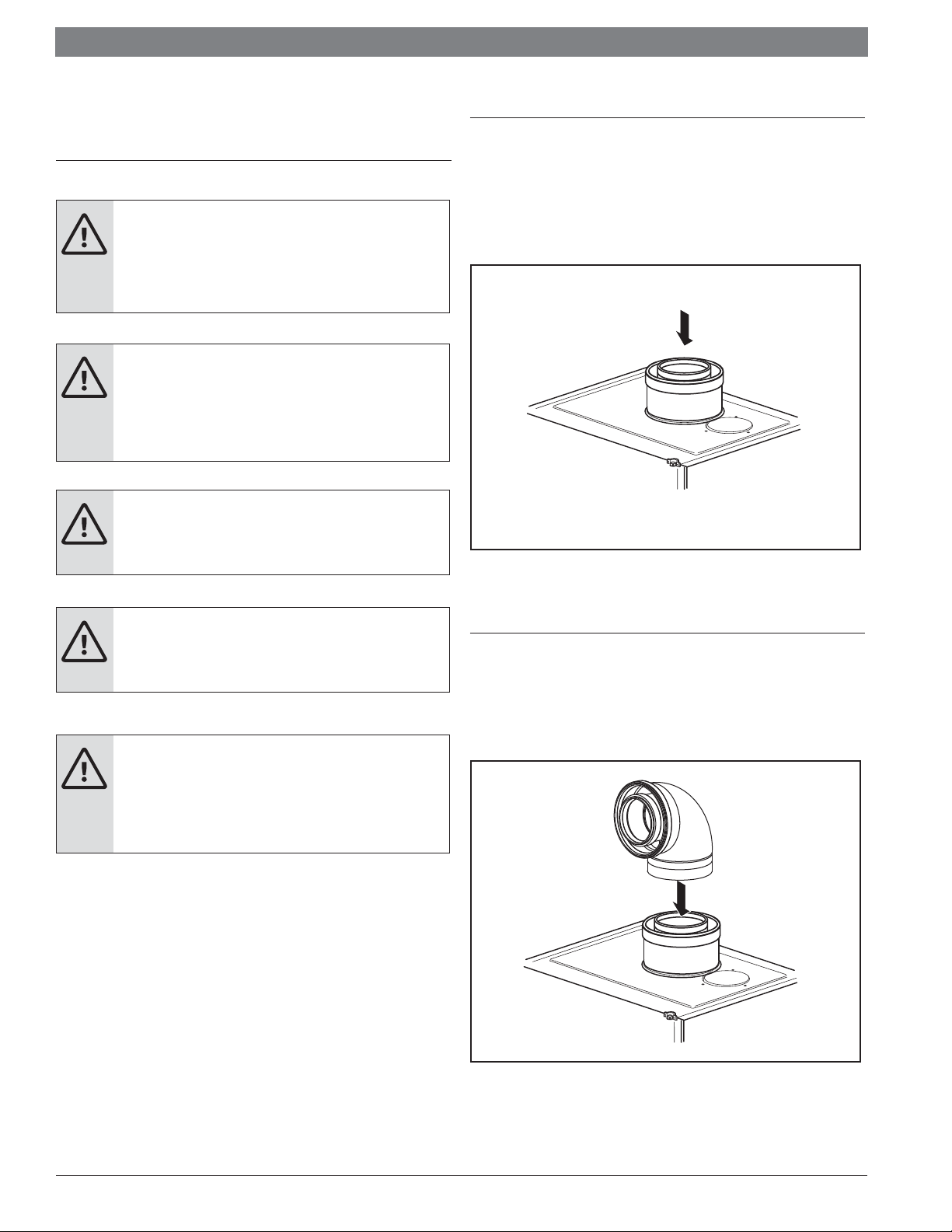
DANGER: Carbon monoxide poisoning.
Exhaust gas must be vented to outside using
approved vent material. (In Canada use
only ULCS636 approved material). Vent and
combustion air connector piping must be sealed
gas-tight to prevent flue gas spillage, carbon
monoxide emissions and risk of fire, resulting in
severe personal injury or death. Approved vent
terminations must be used when penetrating to
the outside.
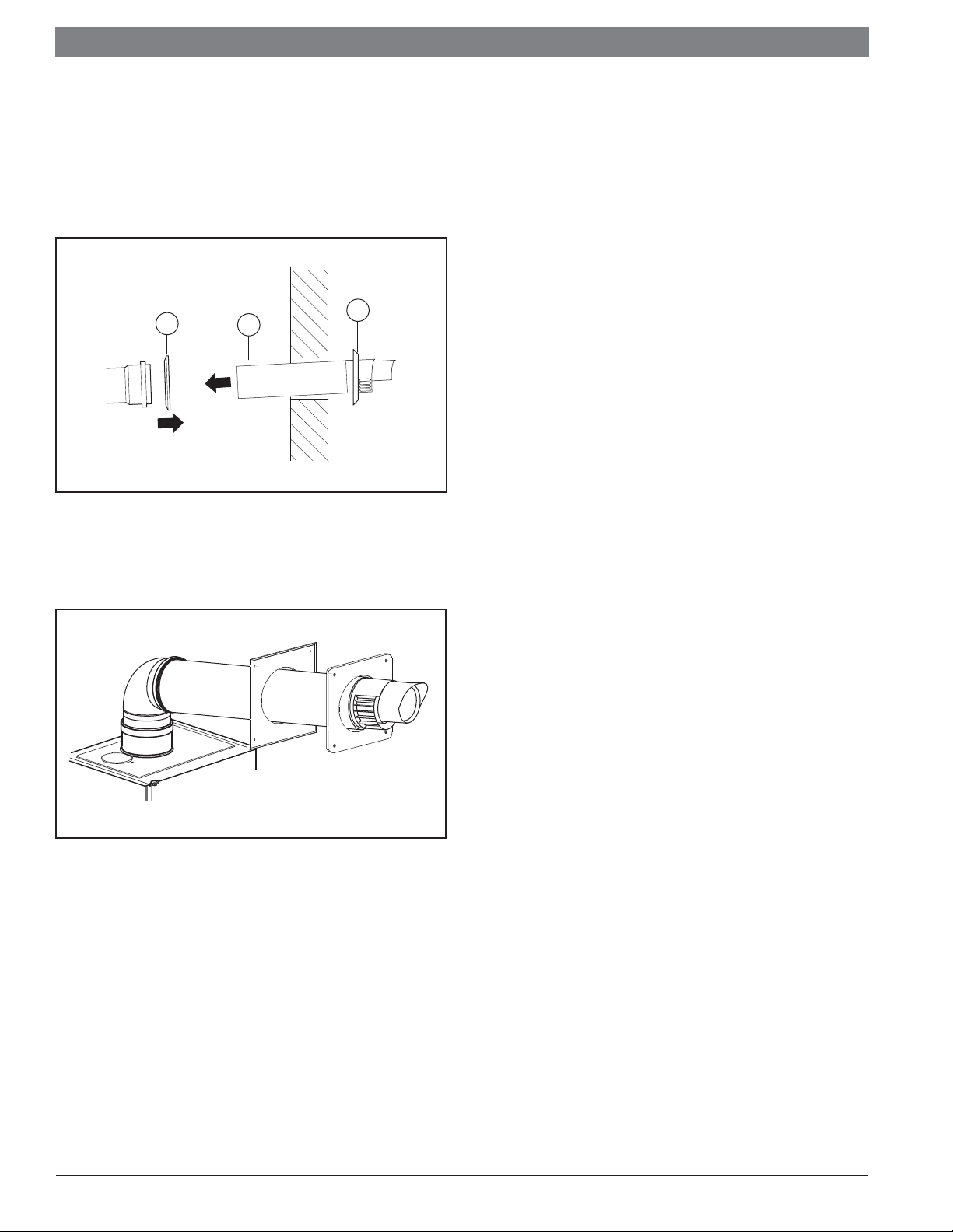
WARNING:
Do not obstruct the flow of combustion and
ventilation air.
NOTICE:
The complete installation must comply with
national, state, and local code. The installation
instructions in both the gas appliance installation
manual and this vent system installation manual
must be followed exactly.
NOTICE:
The concentric horizontal vent terminal is
intended for installation only with the GB162
series boilers (hereafter referred to as
"appliance"):
- GB162-80 kW
- GB162-100 kW