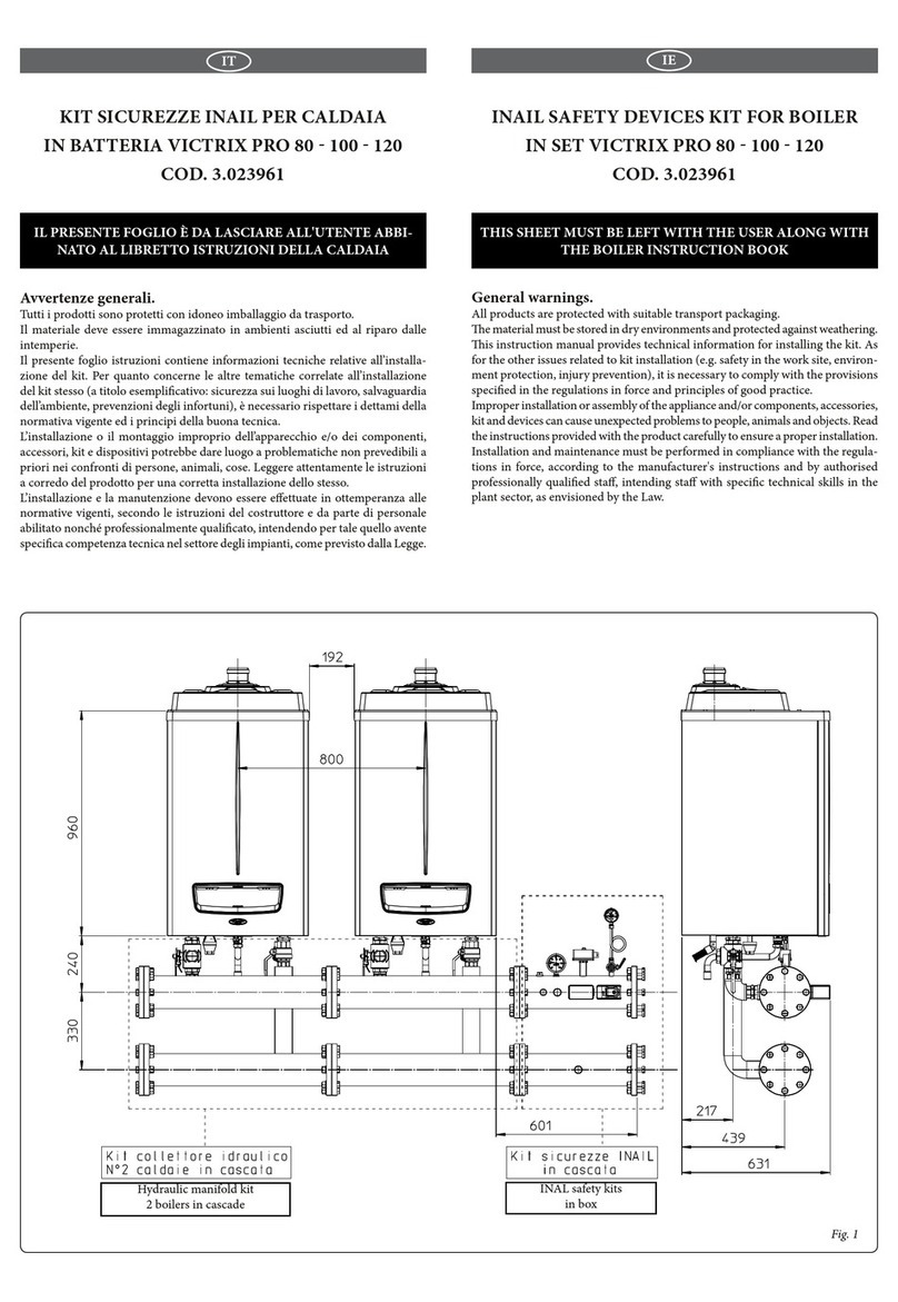
Caratteristiche principali.
Il kit armadio viene fornito completo per la messa in opera.
Comprende 4 piedini di sostegno che oltre a garantire la stabilità
dell'installazione ne permettono la movimentazione mediante un
carrello elevatore o un transpallet da posizionare sotto il telaio
dell'armadio.
In alternativa è possibile spostare l'armadio mediante i 4 golfari
presenti nella parte superiore.
L'armadio ha un'anta apribile a 180° compresa di serratura.
Il grado di protezione è IPX5D e può essere installato all'esterno
a cielo completamente scoperto.
Installazione.
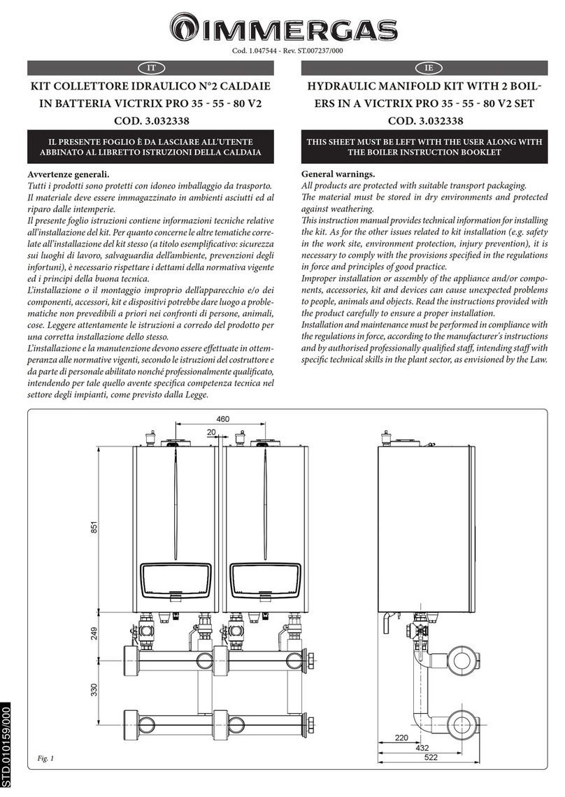
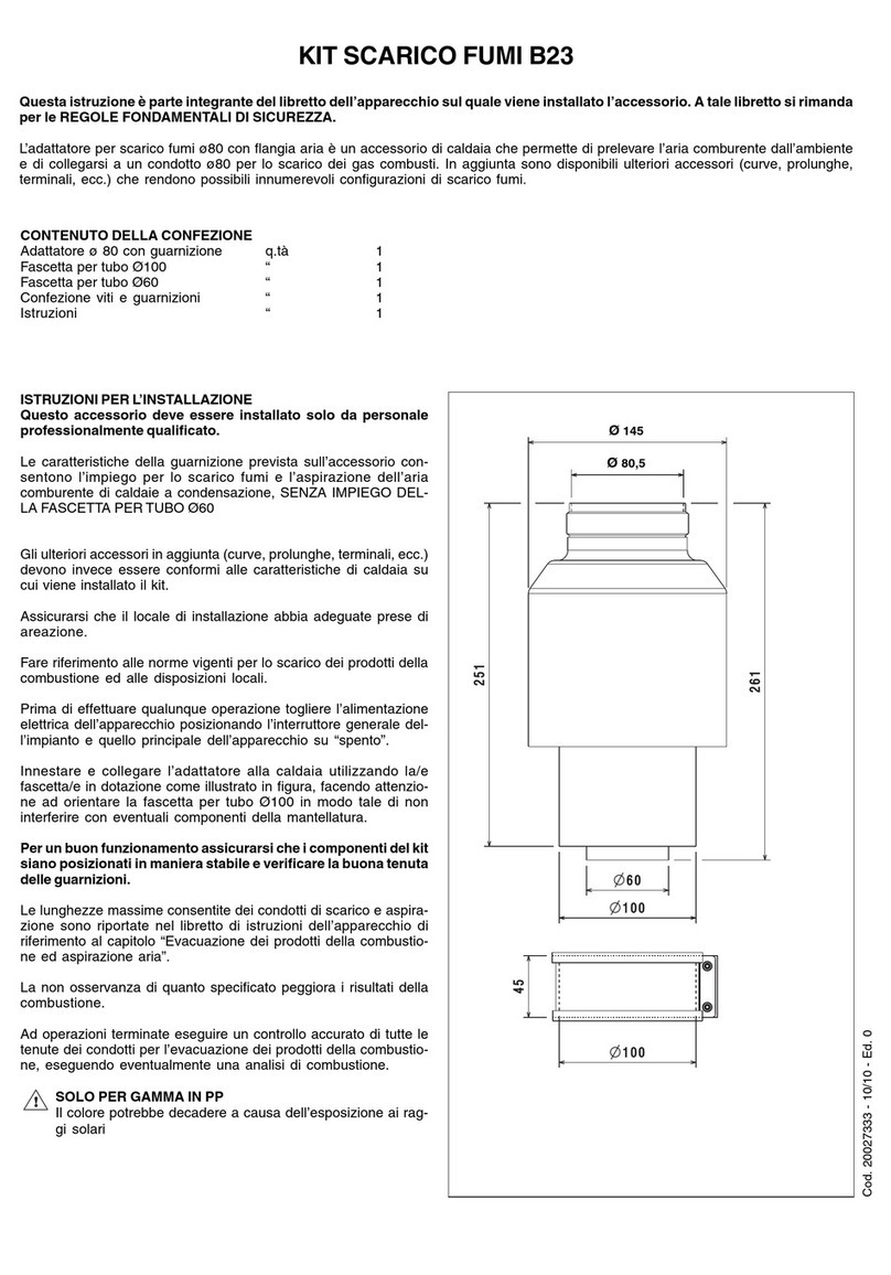
Eseguire il livellamento dell'armadio allentando i dadi (pos. 3, Fig.
2) e ruotando i piedini di sostegno (pos. 4, Fig. 2). Ottenuto un
perfetto livellamento, serrare i dadi (pos. 3, Fig. 2).
Aprire l'anta dell'armadio, allentare le viti (pos. 2, Fig. 2) e, a
seconda del modello di caldaia da installare, spostare i supporti
sostegno caldaia (pos. 1, Fig. 2) come indicato in gura 2.
Al termine della regolazione serrare le viti (pos. 2, Fig. 2).
N.B.: in dotazione con l'armadio vengono fornite le fascette Ø
80 e Ø 100 da utilizzare a secondo della fumisteria installata (Ø
80 per i modelli Victrix Pro 35-55-80 V2 e Ø 100 per i modelli
Victrix Pro 100-120-150 V2).
Le fascette devono stringere la guarnizione sul tubo uscita fumi
facendo attenzione a fermare le 4 linguette della guarnizione stessa.
L'armadio è predisposto per l'installazione della fumisteria Ø 80.
Nel caso si desideri installare la fumisteria Ø 100 è necessario
smontare la angia di bloccaggio e relativa guarnizione per fu-
misteria Ø 80 (pos. 5, Fig. 2) e montare la guarnizione per fumi-
steria Ø 100 (fornita in dotazione) rimontando successivamente
la angia rimossa.
Main features.
e cabinet kit is supplied complete for commissioning.
It includes 4 support feet that ensure stable installation and its
handling by forkli truck or transpallet to be positioned below
the cabinet frame.
Alternatively, you can move the cabinet by means of 4 eyebolts
in the upper part.
e cabinet has a door that can be opened by 180 inclusive of lock.
e degree of protection is IPX5D and it can be installed outdoors.
Installation.
Level the cabinet by loosening the nuts (pos. 3, Fig. 2) and rotat-
ing the support feet (pos. 4, Fig. 2). Once perfectly leve, tighten
the nuts (pos. 3, Fig. 2).
Open the door of the cabinet, loosen the screws (pos. 2, Fig. 2)
and, depending on the boiler model to be installed, move the
boiler supports (pos. 1, Fig. 2) as shown in gure 2.
Once adjusted, tighten the screws (pos. 2, Fig. 2).
N.B.: the Ø 80 and Ø 100 clamps are supplied with the cabinet to
be used according to the ue system installed (Ø 80 for Victrix
Pro 35-55-80 V2 models and Ø 100 for Victrix Pro 100-120-V2
models).
e clamps must tighten the gasket on the ue outlet pipe, ma-
king sure to block the 4 gasket clips. e cabinet is set up for the
installation of the Ø 80 ue.
To install the Ø 100 ue, disassemble the locking ange and relative
gasket for the Ø 80 ue (pos. 5, Fig. 2) and assemble the gasket for
the Ø 100 ue (supplied) and then reassemble the removed ange .
2
==
y
1
1
2
3
4
5
y (mm)
Victrix Pro 35-55-80 V2 340
Victrix Pro 100-120-150 V2 470
STD.010374/000
