Viessmann GENO-Neutra V N-70 Quick guide

5601311 GB/en 10/2017
Installation and service
instructions
for contractors
VIESMANN
Neutralising system
Part no. 7441823, Grünbeck part no. 410480
Part no. 7437829, Grünbeck part no. 410490
Safety instructions
Please follow these safety instructions closely to prevent accidents
and material losses.
Safety instructions explained
Note
Details identified by the word "Note"
contain additional information.
Target group
These instructions are exclusively
intended for authorised contractors.
■ Work on electrical equipment must
only be carried out by a qualified
electrician.
Regulations to be observed
■ National installation regulations
■ Statutory regulations for the preven-
tion of accidents
■ Statutory regulations for the protec-
tion of the environment
■ Codes of practice of the relevant
trade associations
■ All relevant safety regulations as
defined by DIN, EN, DVGW, VDE
and locally applicable standards
aÖNORM, EN and ÖVE
cSEV, SUVA, SVTI, SWKI and
SVGW

2
Working on the system
■ Isolate the system from the power
supply (e.g. by removing the sepa-
rate fuse or by means of a mains iso-
lator) and check that it is no longer
'live'.
■ Safeguard the system against recon-
nection.
Product information
Neutralising system
■GENO®-Neutra V N-70 (part no. 7441823)
■GENO®-Neutra V N-210 (part no. 7437829)
Suitable for neutralising condensate
(pH value raised above 6.5) from gas
boilers/gas condensing boilers and/or
flue systems (made from stainless
steel, plastic, glass, graphite and
ceramics). For condensate levels of up
to max. 70 l/h or 210 l/h.
Safety instructions (cont.)
5601311

3
Dimensions and connections
Part no. 7441823
410
421
110
165
140
230
CBA 70
ACondensate supply DN 20 (from
heat source)
BCondensate drain DN 20 (to drain-
age system)
COverflow aperture
Part no. 7437829
600
682
400
80
80
170
185
AB
ACondensate supply DN 20 (from
heat source)
BCondensate drain DN 25 (to drain-
age system)
Preparing for installation
5601311

4
Siting
Requirements of the installation room
■ Frost protection
■ Protection against chemicals, dyes,
solvents and dust
■ Protection against high radiation tem-
peratures and direct sunlight
■ Sufficiently large, horizontal, level
and load-bearing installation surface
■ Easy accessibility for maintenance
work
■ Existing bottom drain (sewer connec-
tion min. DN 40) must allow drainage
free of backpressure
Note
If the installation room does not have a
bottom drain:
■ Provide an alarm facility to indicate
any fault and, if required, stop the
heat source in order to prevent a sys-
tem overflow and any consequential
damage.
■ The condensate lifting system
V AH-300 (accessories) can be con-
nected downstream.
Choose an installation location that
means the supply and drain hoses are
as short as possible.
Preparing for installation (cont.)
5601311

5
20
> 0°
C A
≥
D
20
≥
> 0°
B A
> 0°
ANeutralising system
BCondensate supply from the heat
source
CCondensate drain to the drainage
system (for part no. 7441823)
DCondensate drain to the drainage
system (for part no. 7437829)
1. Install the neutralising system in the
required location.
2. Route the supply hose from the
heat source to the neutralising sys-
tem with a fall. Secure the hose
with hose clips.
Positioning and connecting
5601311

6
Note
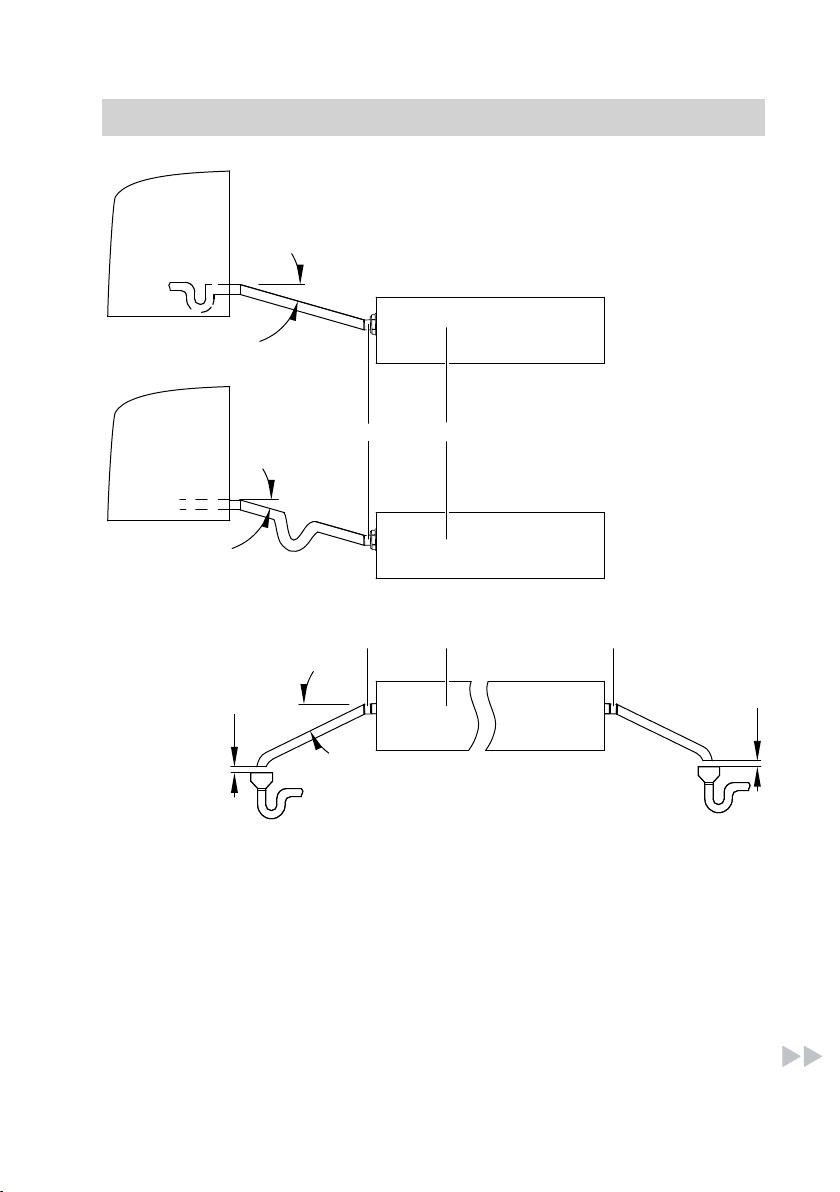
■ If the heat source does not have
a siphon, the supply hose must
be routed in a U-bend.
■ Never step on the hose. Protect
the hose against mechanical
damage.
3. Route the drain hose from the neu-
tralising system to the drainage
system with a fall. Secure the hose
with hose clips.
Note
■ Never connect the drain hose
directly to the sewage system. To
avoid retrograde bacterial con-
tamination from the sewage sys-
tem, observe the minimum clear-
ance of 20 mm (see diagram).
■ Never step on the hose. Protect
the hose against mechanical
damage.
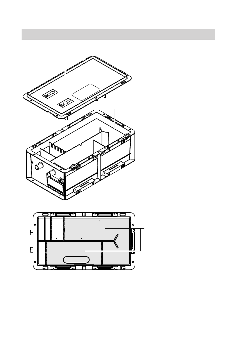
Commissioning and adjustment
1. Remove the neutralising system
cover.
2. For part no. 7437829: Assemble
the slot-together casing. The size of
the fill area for neutralising granu-
late can be determined subject to
the condensate level (see
page 10).
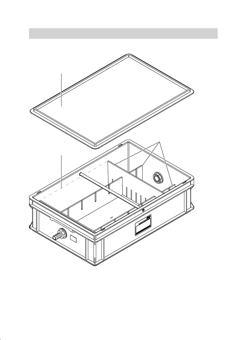
3. Fill the relevant area with neutralis-
ing granulate (see pages 8
to 10).
4. Fill the neutralising system with
water.
5. Check the container and the supply
and drain lines for leaks.
6. Close the neutralising system
cover.
7. Start the heat source.
8. Record commissioning on
page 17.
Note
During commissioning, instruct the sys-
tem user in the operation of the appli-
ance.
Positioning and connecting (cont.)
5601311

7
Inspection and maintenance intervals
■Regular inspection can be carried
out by the user or any authorised,
qualified person. Inspection should
initially be carried out at short inter-
vals, then as required, but at least
every 6 months
■Maintenance work must be carried
out regularly subject to the volume,
contamination and pH value of the
condensate, but at least once a year.
It must be carried out by an approved
heating contractor or personnel
trained by this approved heating con-
tractor.
Inspection and maintenance
5601311

8
Part no. 7441823
A
B
C
ACover
BGranulate fill level
CFill area for the neutralising granu-
late
Inspection and maintenance (cont.)
5601311

9
Part no. 7437829
A
B
C
ACover
BGranulate fill level
CPCBs
Inspection and maintenance (cont.)
5601311

10
DF
E
Changeable fill area for neutralising
granulate
DUp to 110 l/h (3 fields)
EUp to 160 l/h (4 fields)
FUp to 210 l/h (5 fields)
Inspection
1. Remove neutralising system cover
A.
If an overflow alarm switch (acces-
sories) is installed, isolate this from
the power supply and remove it
together with cover A from the
neutralising system.
2. Check the supply and drain hose
for deposits and clean if required.
3. Check the water level in the neu-
tralising system. Top up the water if
required.
4. Check the pH value at the conden-
sate drain. The measured value
must be above 6.5.
5. Top up with neutralising granulate if
required. Observe granulate fill
level B (see pages 8 and 9).
Note
Only use original GENO®-Neutralit
Hz neutralising granulate.
6. Check the tightness of the neutral-
ising container and the condensate
supply and drain lines.
Inspection and maintenance (cont.)
5601311

11
7. Close cover A again.
If an overflow alarm switch (acces-
sories) is installed, before closing
the cover:
■ Reconnect the power supply for
the overflow alarm switch.
■ Check the fault message func-
tion: simulate backpressure by
raising the drain hose temporarily
and filling the container with
water to the level of the overflow
aperture.
■ Close the cover.
■ The overflow alarm switch must
be fully inserted into the locking
ring fitting.
8. Record inspection on page 17.
Service
01. Stop the condensate or divert it
into a suitable collector tank.
02. Remove neutralising system cover
A.
If an overflow alarm switch (acces-
sories) is installed, isolate this from
the power supply and remove it
together with cover A from the
neutralising system.
03. Remove neutralising granulate
from the system and pour into the
foil bag provided with the mainte-
nance set.
Note
■ Use a wet vacuum cleaner.
■ For disposal, see page 12.
04. Clean container.
05. Check the supply and drain hose
for deposits and clean if required.
06. Fill the relevant area of the neutral-
ising container with neutralising
granulate. Observe granulate fill
level B (see pages 8 and 9).
Note
Only use original GENO®-Neutralit
Hz neutralising granulate.
07. Fill the system with water.
08. Check the tightness of the neutral-
ising container and the condensate
supply and drain lines. If required,
replace damaged or old compo-
nents.
Inspection and maintenance (cont.)
5601311

12
09. Close cover A again.
If an overflow alarm switch (acces-
sories) is installed, before closing
the cover:
■ Reconnect the power supply for
the overflow alarm switch.
■ Check the fault message func-
tion: simulate backpressure by
raising the drain hose tempora-
rily and filling the container with
water to the level of the overflow
aperture.
■ Close the cover.
■ The overflow alarm switch must
be fully inserted into the locking
ring fitting.
10. Record service on page 17.
Disposal of neutralising granulate
■ Neutralising granulate in the deliv-
ered condition, waste code number
010102, can be disposed of with
domestic waste in accordance with
the relevant regulations after consult-
ing the disposal company and the rel-
evant authorities.
■ Hydroxide sludge, which can occur
when the system is cleaned, must be
separately collected and disposed of
using a suitable container via local
approval bodies. It can be declared
as "hydroxide sludge containing
metal", waste code number 51113.
The latest version of the TA Abfall
(German technical instructions on
hazardous waste) must be observed.
Inspection and maintenance (cont.)
5601311

13
System characteris-
tics
Cause Action
pH value at the drain
briefly above 10
■ Longer idle period ■ No immediate measures re-
quired
■ Repeat pH value check after
constant operation over an ex-
tended period
pH value at the drain
below 6.5 after exten-
ded operating time
■ Neutralising gran-
ulate used up
■ Top up neutralising granulate
■ Where there are sludge depos-
its, clean the system
■ Neutralising gran-
ulate sticking or
hardened due to
deposits
■ Neutralising gran-
ulate dried out and
hardened due to
extended idle peri-
od
■ Loosen neutralising granulate
by adding water, and carry out
maintenance if required
■ Filter plates conta-
minated
■ Clean the filter plates
pH value at the drain is
constantly above 10 or
below 6.5
■ Inappropriate neu-
tralising granulate
fill volume
■ Change the neutralising granu-
late fill volume (change the fill
area)
pH > 10: less granulate
pH < 6.5: more granulate
Function description
In the neutralising container, the layout
is in the direction of flow: sedimentation
zone for contamination, neutralising
granulate filling and condensate collec-
tion zone.
The condensate flows into the sedi-
mentation zone of the neutralising con-
tainer. Via the integral filter plate, the
condensate is separated and flows
through the neutralising granulate fill-
ing. The granulate is thereby partially
dissolved and the condensate is neu-
tralised.
Troubleshooting
5601311

14
For part no. 7441823, above the drain
connector is an overflow aperture,
which, when the condensate drain is
obstructed, enables the condensate to
escape from the neutralising container.
Parts list for part no. 7441823
When ordering spare parts:
Quote the part no. (see type plate) and
its position number (as per this parts
list).
Standard parts are available from your
local supplier.
001
005
009
007 008
006002
004
Function description (cont.)
5601311

15
Pos. Part
001 Casing
002 Cover
004 Hose DN 20 (5 m)
005 Overflow alarm switch (accessories)
006 Service kit for the neutralising system:
■ Bag with neutralising granulate (8 kg)
■ pH indicator stick (3 pce)
■ Foil bag for disposal of used neutralising granulate
■ Installation and service instructions
007 pH indicator stick (3 pce)
008 pH indicator stick (100 pce)
009 Installation and service instructions
Parts not shown:
003 Plug
010 Bag with neutralising granulate (8 kg)
011 Condensate lifting system V AH-300 (accessories)
012 Alarm delay (accessories)
Parts list for part no. 7441823 (cont.)
5601311

16
When ordering spare parts:
Quote the part no. (see type plate) and
its position number (as per this parts
list).
Standard parts are available from your
local supplier.
014
012 013
011
004
001
007
007
008
006
009
010002
005
003
Parts list for part no. 7437829
5601311

17
Pos. Part
001 Casing
002 Cover
003 Slot-together casing
004 Hose DN 20 (5 m)
005 Hose DN 25 (5 m)
006 Hose connection DN 20
007 Flat gasket
008 Hose connection DN 25
009 Supporting rod
010 Overflow alarm switch (accessories)
011 Service kit for the neutralising system:
■ Bag with neutralising granulate (3 x 8 kg)
■ pH indicator stick (3 pce)
■ Foil bag (3 pce) for disposal of used neutralising granulate
■ Installation and service instructions
012 pH indicator stick (3 pce)
013 pH indicator stick (100 pce)
014 Installation and service instructions
Parts not shown:
015 Bag with neutralising granulate (8 kg)
016 Bag with neutralising granulate (25 kg)
017 Condensate lifting system V AH-300 (accessories)
018 Alarm delay (accessories)
Report
Commissioning Maintenance/Service Maintenance/Service
Date:
By:
Parts list for part no. 7437829 (cont.)
5601311

18
Maintenance/Service Maintenance/Service Maintenance/Service
Date:
By:
Maintenance/Service Maintenance/Service Maintenance/Service
Date:
By:
Maintenance/Service Maintenance/Service Maintenance/Service
Date:
By:
Maintenance/Service Maintenance/Service Maintenance/Service
Date:
By:
Report (cont.)
5601311

19
Part no. 7441823 7437829
Grünbeck part no. 410480 410490
Fuel/process Gas condensing
technology
Gas condensing
technology
Max. neutralising output l/h 70 210
Neutralising granulate GENO®-Neutralit
Hz
GENO®-Neutralit Hz
Neutralising granulate fill
volume
kg 8 24
Service life months 12 12
Amount of condensate that
can be neutralised
■ With standard condensate
to DVGW-VP-114, pH 3
m363 190
This corresponds to full
boiler utilisation hours
bVH 900 900
■ With standard condensate
with min. pH 3.2
m3105 315
This corresponds to full
boiler utilisation hours
bVH 1500 1500
Weight
■ In the delivered condition kg 12 33
■ In operation (filled) approx. kg 15 45
Specification
5601311

20
Applicability
Part no. (see type plate on the neutralising system)
7441823 7437829
Viessmann Limited
Hortonwood 30, Telford
Shropshire, TF1 7YP, GB
Telephone: +44 1952 675000
Fax: +44 1952 675040
E-mail: [email protected]
Viessmann Werke GmbH & Co. KG
D-35107 Allendorf
Telephone: +49 6452 70-0
Fax: +49 6452 70-2780
www.viessmann.com
5601311 Subject to technical modifications.
This manual suits for next models
5
Table of contents
Other Viessmann Boiler Supplies manuals
Popular Boiler Supplies manuals by other brands

Xylem
Xylem McDonnell & Miller GuardDog 751P Series instruction manual

Miura
Miura MP1-200 installation manual

Grant
Grant SpiraPod installation instructions

Hydrolevel Company
Hydrolevel Company CycleGard CG450 Series manual

Rheem
Rheem Ruud TRD Technical service bulletin

TriangleTube
TriangleTube PTRKIT304 installation instructions