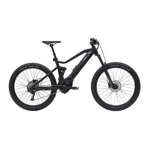
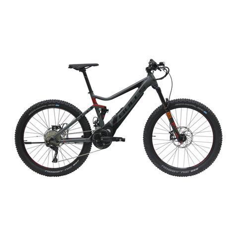
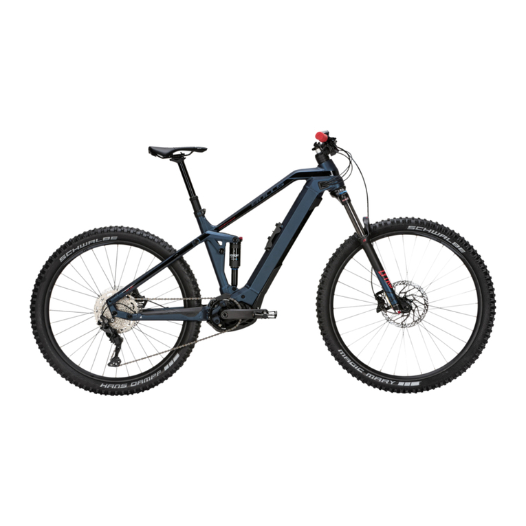
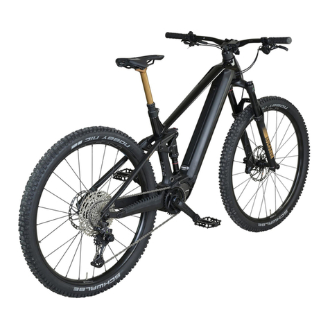
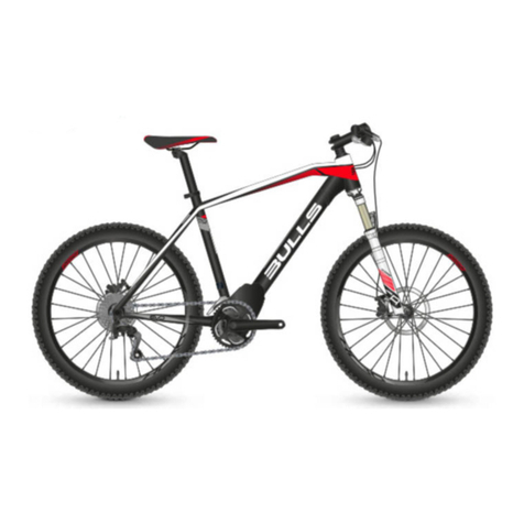
Bulls Iconic EVO 2 User manual

23-15-2007 … 23-15-2009, 23-15-2016 … 23-15-2022, 23-15-3027, 23-15-3037
MY23B0a - 52_1.0_31.08.2022
Cross Rider EVO 1, Iconic EVO 1 27.5″, Iconic EVO 2 27.5″, Iconic EVO 3 27.5″, Iconic EVO Belt 27.5″,
Iconic EVO TR1 27.5″
Original operating instructions for BULLS pedelecs
with BOSCH Intuvia 100 display and
LED Remote on-board computer
IMPORTANT
READ CAREFULLY BEFORE USE
KEEP SAFE TO CONSULT AT A LATER DATE

MY23B0a - 52_1.0_31.08.2022 1
Contents
Contents
1 About these operating instructions
1.1 Manufacturer 12
1.2 Laws, standards and directives 12
1.3 Language 12
1.4 For your information 12
1.4.1 Warnings 12
1.4.2 Markups 12
1.5 Aim of the operating instructions 13
1.6 Type number and model 14
1.7 Frame number 14
1.8 Identifying the operating instructions 14
2Safety
2.1 Residual risk 15
2.1.1 Risk of fire and explosion 15
2.1.2 Electric shock 17
2.1.3 Risk of a crash 17
2.1.4 Risk of amputation 17
2.1.5 Key breaking off 17
2.1.6 Malfunctions due to Bluetooth® 18
2.2 Toxic substances 19
2.2.1 Toxic substances 19
2.2.2 Irritants and corrosive substances 19
2.3 Requirements for the rider 19
2.4 Vulnerable groups 19
2.5 Personal protective equipment 20
2.6 Safety guards 20
2.7 Safety markings and safety instructions 20
2.8 What to do in an emergency 21
2.8.1 Dangerous situation in road traffic 21
2.8.2 Leaked brake fluid 21
2.8.3 Battery vapour emission 21
2.8.4 Battery fire 22
2.9 Data privacy information 23
3 Description
3.1 Proper use 24
3.1.1 Pedelec type 24
3.1.2 Improper use 24
3.1.3 Maximum permitted total weight (PTW) 25
3.1.4 Environmental requirements 26
3.1.5 Area of use 26
3.2 Nameplate 28
3.3 Components 29
3.3.1 Overview 29
3.3.2 Chassis 30
3.3.2.1 Frame 30
3.3.2.2 Rear frame damper 33
3.3.2.3 Steering system 36
3.3.2.4 Steering headset 36
3.3.2.5 Stem 36
3.3.2.6 Handlebars 37
3.3.2.7 Suspension fork 37
3.3.3 Wheel 45
3.3.3.1 Tyres 45
3.3.3.2 Tube-type tyre 45

MY23B0a - 52_1.0_31.08.2022 2
Contents
3.3.3.3 Rim 48
3.3.3.4 Valve 48
3.3.3.5 Spoke 48
3.3.3.6 Spoke nipples 48
3.3.3.7 Hub 49
3.3.4 Saddle 50
3.3.4.1 Ladies’ saddle 51
3.3.4.2 Men’s saddle 51
3.3.5 Seat post 52
3.3.5.1 Patent seat post 52
3.3.5.2 Suspension seat post 52
3.3.6 Brake 55
3.3.6.1 Mechanical brake 55
3.3.6.2 Hydraulic brake 55
3.3.6.3 Disc brake 56
3.3.7 Mechanical drive system 57
3.3.7.1 Chain drive layout 57
3.3.7.2 Belt drive layout 57
3.3.8 Electric drive system 58
3.3.8.1 Motor 58
3.3.8.2 Charger 58
3.3.8.3 Lighting 58
3.3.8.4 Rechargeable battery 59
3.3.9 On-board computer 60
3.3.10 Display 60
3.4 Description of controls and screens 61
3.4.1 Handlebars 61
3.4.2 BOSCH LED Remote on-board computer 62
3.4.2.1 System message 63
3.4.2.2 Creating a user account 64
3.4.2.3 Software updates 64
3.4.2.4 Activity tracking 64
3.4.2.5 Lock function 64
3.4.3 BOSCH display, Intuvia 100 65
3.4.3.1 Settings 66
3.4.4 Handbrake 67
3.4.5 Suspension and damping 68
3.4.5.1 Air valve and sag setting wheel 68
3.4.5.2 Damper adjuster 69
3.4.6 Battery level indicator (battery) 72
3.4.6.1 Battery level indicator (battery) 72
3.5 Technical data 73
3.5.1 Pedelec 73
3.5.2 Emissions 73
3.5.3 Bicycle lighting 73
3.5.4 Display BDS3YYY 73
3.5.5 LED Remote on-board computer 73
3.5.6 BOSCH Intuvia 100 display 73
3.5.6.1 BOSCH Performance Line CX motor 74
3.5.7 Rechargeable battery 74
3.5.7.1 BOSCH PowerTube 500 battery 74
3.5.7.2 BOSCH PowerTube 625 battery 74
3.5.7.3 BOSCH PowerTube 750 battery 74
3.5.7.4 BOSCH PowerPack 400 battery 74
3.5.7.5 BOSCH PowerPack 500 battery 75
3.5.7.6 BOSCH PowerPack 600 battery 75
3.5.7.7 BOSCH PowerPack 800 battery 75
3.5.8 Tyres 76
3.5.8.1 SCHWALBE puncture protection level 76

MY23B0a - 52_1.0_31.08.2022 3
Contents
3.5.9 Saddle 77
3.5.9.1 BROOKS ENGLAND saddle width 77
3.5.9.2 ERGON 77
3.5.9.3 SELLE ROYAL saddle width 77
3.5.10 Seat post 78
3.5.10.1 Suspension seat post LIMOTEC, A3/A3 Plus 78
3.5.10.2 LIMOTEC seat post, A1/A1L 80
3.5.11 Torque 82
4 Transporting and storing
4.1 Weight and dimensions for transportation 93
4.2 Designated handles, lifting points 93
4.3 Transportation 94
4.3.1 Using the transport securing system 94
4.3.2 Transporting the pedelec 94
4.3.2.1 By car 94
4.3.2.2 By train 94
4.3.2.3 By local transport 95
4.3.2.4 By long-distance bus 95
4.3.2.5 On flights 95
4.3.3 Shipping a pedelec 95
4.3.4 Transporting the battery 95
4.3.5 Shipping the battery 95
4.4 Storing 96
4.4.1 Pedelec 96
4.4.2 On-board computer, display and charger 96
4.4.3 Rechargeable battery 96
4.4.4 Break in operation 97
4.4.4.1 Preparing a break in operation 97
4.4.4.2 Carrying out a break in operation 97
5 Assembly
5.1 Unpacking 98
5.2 Required tools 98
5.3 Commissioning 99
5.3.1 Checking the battery 99
5.3.2 Preparing the battery 100
5.3.2.1 Retrofitting the PowerTube adapter 100
5.3.2.2 Fit battery cover onto Bosch PowerTube 625 battery (horizontal) 101
5.3.2.3 Fit battery cover onto Bosch PowerTube 500 battery (horizontal) 102
5.3.3 Adjusting the suspension system to body weight 103
5.3.3.1 Adjusting SR SUNTOUR steel suspension fork to body weight 103
5.3.3.2 Adjusting seat post to body weight 103
5.3.4 Installing the wheel in the SUNTOUR fork 104
5.3.4.1 Screw-on axle (12AH2 and 15AH2) 104
5.3.4.2 20 mm cross axle 105
5.3.4.3 Q-LOC quick release 107
5.3.5 Preparing the wheel 108
5.3.6 Fitting the pedals 109
5.3.7 Preparing the LIMOTEC seat post 110
5.3.8 Checking the stem and handlebars 111
5.3.8.1 Checking the connections 111
5.3.8.2 Checking stem is firmly in position 111
5.3.8.3 Checking the bearing clearance 111
5.4 Selling the pedelec 111

MY23B0a - 52_1.0_31.08.2022 4
Contents
6 Operation
6.1 Risks and hazards 112
6.2 Tips for a greater range 114
6.3 Error message 115
6.3.1 On-board computer 115
6.3.1.1 Less critical errors 115
6.3.1.2 Critical errors 115
6.3.2 Rechargeable battery 115
6.4 Instruction and customer service 116
6.5 Adjusting the pedelec 116
6.5.1 Preparing 116
6.5.2 Determining the sitting position 117
6.5.3 Seat post 118
6.5.3.1 Adjusting the seat post to body weight 118
6.5.4 Saddle 118
6.5.4.1 Replacing the saddle 118
6.5.4.2 Determining saddle shape 119
6.5.4.3 Determining minimum saddle width with corrugated cardboard 120
6.5.4.4 Determining minimum saddle width with gel cushion 120
6.5.4.5 Calculating the saddle width 121
6.5.4.6 Selecting the saddle hardness 121
6.5.4.7 Adjusting the saddle hardness 121
6.5.4.8 Straighten saddle 122
6.5.4.9 Adjusting the saddle height 122
6.5.4.10 Setting the saddle height with the remote control 123
6.5.4.11 Adjusting the saddle position 124
6.5.4.12 Adjusting the saddle tilt 124
6.5.4.13 Checking saddle stability 124
6.5.5 Handlebars 125
6.5.5.1 Replace handlebars 125
6.5.5.2 Adjusting the handlebar width 125
6.5.5.3 Adjusting the hand position 125
6.5.5.4 Adjusting the handlebars 126
6.5.6 Stem 127
6.5.6.1 Replacing the handlebars 127
6.5.6.2 Adjusting the handlebar height with quick release 127
6.5.6.3 Checking the stem stability 127
6.5.6.4 Adjusting the quick release clamping force 127
6.5.6.5 Setting the quill stem 128
6.5.6.6 Adjusting the Ahead stem 128
6.5.6.7 Adjusting the angle-adjustable stem 129
6.5.7 Handles 130
6.5.7.1 Replacing the handles 130
6.5.7.2 Adjusting ergonomic handles 130
6.5.7.3 Checking handlebar stability 130
6.5.8 Tyres 131
6.5.8.1 Replacing tyres 131
6.5.8.2 Adjust tyre pressure 131
6.5.9 Brake 133
6.5.9.1 Replacing brakes 133
6.5.9.2 Retracting the brake linings 133
6.5.9.3 Change handbrake position 133
6.5.9.4 Change handbrake inclination angle 134
6.5.9.5 Determining the grip distance 134
6.5.9.6 Grip distance on a SHIMANO ST-EF41 handbrake 135
6.5.10 Gear shift 136
6.5.10.1 Replacing the gear shift 136
6.5.10.2 Adjusting the SHIMANO shifter 136
6.5.11 Suspension and damping 137

MY23B0a - 52_1.0_31.08.2022 5
Contents
6.5.12 Adjusting sag (fork) 137
6.5.12.1 Adjusting the sag for the SR SUNTOUR air suspension fork 139
6.5.12.2 Adjusting the sag for the SR SUNTOUR steel suspension fork 143
6.5.13 Adjust the rear frame damper sag 144
6.5.13.1 Adjusting Suntour sag for the rear frame damper 146
6.5.14 Fork rebound damping 148
6.5.14.1 Adjusting the SR SUNTOUR fork rebound damping 149
6.5.15 Adjusting the rear frame damper rebound damper 150
6.5.16 Setting high- and low-speed rebound damper in rear frame damper 150
6.5.16.1 Adjusting the Suntour rear frame damper 151
6.5.17 Riding light 152
6.5.17.1 Replacing the headlight 152
6.5.17.2 Replacing the rear light and (spoke) reflector 152
6.5.17.3 Setting the riding light 152
6.5.17.4 Adjusting the headlight 153
6.5.18 Adjusting the on-board computer 154
6.5.18.1 Creating a user account 154
6.5.18.2 Connecting the on-board computer to a smartphone 154
6.5.18.3 Updating the software 154
6.5.18.4 Activating activity tracking 154
6.5.18.5 Setting up the lock function (optional) 155
6.5.18.6 Inserting the battery 155
6.5.18.7 Inserting the display 156
6.5.18.8 Removing the on-board computer 156
6.5.18.9 Securing the on-board display (optional) 156
6.5.18.10 Adjusting the on-board computer 157
6.5.18.11 Adjust on-board computer 158
6.5.18.12 Selecting the language 158
6.5.18.13 Selecting units 158
6.5.18.14 Adjusting the clock 158
6.5.18.15 Setting the time format 158
6.5.18.16 Setting the shift recommendation 159
6.5.18.17 Adjusting the backlight 159
6.5.18.18 Setting the brightness 159
6.5.18.19 Resetting the settings 159
6.6 Accessories 160
6.6.1 Child seat 160
6.6.2 Trailer 161
6.6.2.1 Approval for trailer with Enviolo hub 161
6.6.2.2 Approval for trailer with ROHLOFF hub 162
6.6.3 Pannier rack 162
6.6.4 Panniers and cargo boxes 162
6.6.5 Front baskets 163
6.6.6 Bar ends 163
6.6.7 Kickstands 163
6.6.8 Additional battery headlight 163
6.6.9 Mobile holder 163
6.6.10 Suspension fork coil spring 163
6.6.11 Fixed weather protection systems 163
6.7 Personal protective equipment and accessories for road safety 164
6.8 Before each ride 164
6.9 Straightening the quickly adjustable stem 165
6.10 Using the pannier rack 165
6.11 Raising the kickstand 166
6.12 Using the saddle 166
6.12.1 Using the leather saddle 166
6.13 Using the pedals 166
6.14 Using the bell 166

MY23B0a - 52_1.0_31.08.2022 6
Contents
6.15 Using the handlebars 167
6.15.1 Using multi-position handlebars 167
6.15.2 Using bar ends 167
6.15.3 Using leather handles 167
6.16 Use suspension and damping 168
6.16.1 Locking the suspension 168
6.16.1.1 Locking the SR SUNTOUR suspension fork 168
6.16.1.2 Locking the SR SUNTOUR rear frame damper 169
6.16.2 Adjusting the suspension fork compression damper 170
6.16.2.1 Using the SR Suntour low-speed compression damping 171
6.16.3 Adjusting the rear frame damper compression damper 172
6.16.3.1 Adjusting the SR Suntour compression damper 173
6.17 Using the battery 174
6.17.1 Removing the battery 174
6.17.1.1 Inserting the battery 174
6.17.2 Charging the battery 175
6.18 Using the electric drive system 176
6.18.1 Switching on the electric drive system 176
6.18.2 Switching off the electric drive system 176
6.19 Using the on-board computer 177
6.19.1 Using the diagnosis port 177
6.19.2 Charging the on-board computer battery 177
6.19.3 Using the riding light 178
6.19.4 Setting the brightness of indicators 178
6.19.5 Using the push assist system 178
6.19.6 Selecting the level of assistance 179
6.20 Brake 180
6.20.1 Using the brake lever 180
6.21 Gear shift 181
6.21.1 Using the derailleur gears 181
6.22 Parking 182
6.22.1 Screwing in the quickly adjustable stem 183
6.22.2 Activating the lock function 184
7 Cleaning, servicing and inspection
7.1 Before each ride 189
7.1.1 Checking the guards 189
7.1.2 Checking the frame 189
7.1.3 Checking the fork 189
7.1.4 Checking the rear frame damper 189
7.1.5 Checking the pannier rack 189
7.1.6 Checking the mudguards 189
7.1.7 Check wheel concentricity 189
7.1.8 Checking the quick releases 189
7.1.9 Checking the suspension seat post 190
7.1.10 Checking the bell 190
7.1.11 Checking the handles 190
7.1.12 Checking the USB cover 190
7.1.13 Checking the riding light 190
7.1.14 Checking the brake 190
7.2 After each ride 191
7.2.1 Cleaning the riding light and reflectors 191
7.2.2 Cleaning the suspension fork 191
7.2.3 Maintaining the suspension fork 191
7.2.4 Cleaning the pedals 191
7.2.5 Cleaning the brake 191
7.2.6 Cleaning the suspension seat post 191
7.2.7 Cleaning the rear frame damper 191

MY23B0a - 52_1.0_31.08.2022 7
Contents
7.3 Basic cleaning 192
7.3.1 Clean on-board computer and control panel 192
7.3.2 Cleaning the battery 192
7.3.3 Cleaning the motor 192
7.3.4 Clean Frame, fork, pannier rack, guards and kickstand 193
7.3.5 Cleaning the stem 193
7.3.6 Cleaning the handlebars 193
7.3.7 Clean handles 193
7.3.7.1 Cleaning leather handles 193
7.3.8 Cleaning the seat post 193
7.3.9 Cleaning the saddle 194
7.3.9.1 Cleaning the leather saddle 194
7.3.10 Cleaning the tyres 194
7.3.11 Cleaning the spokes and spoke nipples 194
7.3.12 Clean hub 194
7.3.13 Cleaning the switching elements 194
7.3.13.1 Cleaning the shifter 194
7.3.14 Clean cassette, chain wheels and front derailleur 194
7.3.15 Clean brake 195
7.3.15.1 Clean handbrake 195
7.3.16 Cleaning the brake disc 195
7.3.17 Cleaning the belt 195
7.3.18 Cleaning the chain 195
7.3.18.1 Clean chain, including all-round chain guard 195
7.4 Maintenance 196
7.4.1 Maintain frame 196
7.4.2 Maintain fork 196
7.4.3 Maintain pannier rack 197
7.4.4 Maintain mudguard 197
7.4.5 Servicing the kickstand 197
7.4.6 Maintaining the stem 197
7.4.7 Maintaining the handlebars 197
7.4.8 Maintaining the handles 197
7.4.8.1 Maintaining the rubber handles 197
7.4.8.2 Maintaining the leather handles 197
7.4.9 Maintaining the seat post 198
7.4.9.1 Maintaining the suspension seat post 198
7.4.9.2 Maintaining the carbon seat post 198
7.4.10 Maintaining the rims 198
7.4.11 Maintaining the leather saddle 198
7.4.12 Maintaining the hub 198
7.4.13 Maintaining the spoke nipples 198
7.4.14 Maintaining the gear shift 199
7.4.14.1 Maintaining the rear derailleur articulated shafts and jockey wheel 199
7.4.14.2 Maintaining the shifter 199
7.4.15 Maintaining the pedals 199
7.4.16 Maintaining the chain 199
7.4.16.1 Maintaining the chain and all-round chain guard 200
7.4.17 Maintaining the battery 200
7.4.18 Maintaining the brake 200
7.4.18.1 Maintaining the handbrake 200
7.4.19 Lubricating the Eightpins seat post tube 200
7.5 Inspection 201
7.5.1 Checking the wheel 201
7.5.1.1 Checking tyre pressure 201
7.5.1.2 Checking the tyres 203
7.5.1.3 Checking the rims 204
7.5.1.4 Checking the nipple holes 204
7.5.1.5 Checking the nipple well 204

MY23B0a - 52_1.0_31.08.2022 8
Contents
7.5.1.6 Checking the rim hooks 204
7.5.1.7 Checking the spokes 204
7.5.2 Checking the brake system 205
7.5.2.1 Checking the handbrake 205
7.5.2.2 Checking the hydraulic brake system 205
7.5.2.3 Checking the Bowden cables 205
7.5.2.4 Checking the disc brake 206
7.5.3 Checking the chain 207
7.5.4 Checking the chain tension 207
7.5.4.1 Check tension in derailleur gears 207
7.5.4.2 Check tension in hub gear 207
7.5.5 Checking the belt for wear 207
7.5.5.1 Rough check 207
7.5.5.2 Check 208
7.5.6 Checking the belt 209
7.5.7 Checking the belt for wear 209
7.5.8 Checking the belt sprockets for wear 209
7.5.9 Check belt tension 209
7.5.9.1 Gates Carbon Drive mobile app 210
7.5.9.2 Gates Krikit tension meter 210
7.5.9.3 ECO tension tester 211
7.5.10 Checking the riding light 212
7.5.11 Checking the stem 213
7.5.12 Checking the handlebars 213
7.5.13 Checking the saddle 213
7.5.14 Checking the seat post 213
7.5.14.1 Checking the derailleur gears 213
7.5.14.2 Checking the hub gear 214
7.5.15 Check gear shift 214
7.5.15.1 Checking the electric gear shift 214
7.5.15.2 Check the mechanical gear shift 214
7.5.15.3 Checking the derailleur gears 215
7.5.16 Adjusting gear shift 215
7.5.16.1 Adjusting the ROHLOFF hub 215
7.5.17 Adjusting cable-operated gear shift, dual-cable 215
7.5.18 Adjusting Bowden-cable-operated twist grip, dual-cable 216
7.5.19 Checking kickstand stability 216
8 Inspection and maintenance
8.1 Initial inspection 217
8.2 Major inspection 217
8.3 Component-specific maintenance 217
8.4 Carry out initial inspection 220
8.5 Perform major inspection 221
8.5.1 Inspect frame 228
8.5.1.1 Inspecting the carbon frame 228
8.5.2 Inspecting the pannier rack 228
8.5.3 Inspecting and maintaining the rear frame damper 228
8.5.4 Inspecting the gear hub 229
8.5.4.1 Adjusting the hub with cone bearing 229
8.5.5 Inspecting the stem 229
8.5.6 Inspect and grease steering headset 229
8.5.7 Inspecting the axle with quick release 230
8.5.8 Inspecting the fork 231
8.5.8.1 Inspecting the carbon suspension fork 231
8.5.8.2 Inspecting the suspension fork 231
8.5.9 Inspecting the seat post 232
8.5.9.1 Inspecting the carbon seat post 232
8.5.9.2 Inspecting and greasing BY.SCHULZ suspension seat post 232
8.5.9.3 Inspecting and greasing RS SUNTOUR suspension seat post 233

MY23B0a - 52_1.0_31.08.2022 9
Contents
9 Troubleshooting, fault clearance and repair
9.1 Preventing pain 234
9.1.1 Sitting discomfort 235
9.1.2 Pain in hips 235
9.1.3 Backache 235
9.1.4 Pain in shoulders and nape of neck 236
9.1.5 Numb or aching hands 236
9.1.6 Pain in upper thigh 236
9.1.7 Knee pain 237
9.1.8 Pain in the foot 237
9.2 Troubleshooting and fault clearance 238
9.2.1 Drive system or on-board computer does not start up 238
9.2.2 Errors in assistance function 239
9.2.3 Battery errors 240
9.2.4 Display screen errors 241
9.2.5 Lighting does not work 241
9.2.6 Problems with disc brakes 242
9.2.7 Problems with freewheel 243
9.2.8 Problem with SR SUNTOUR suspension fork 244
9.2.8.1 Rebound too fast 244
9.2.8.2 Rebounding too slowly 245
9.2.8.3 Suspension too soft on inclines 246
9.2.8.4 Excessively hard damping on bumps 247
9.2.9 Problems with SR SUNTOUR rear frame damper 248
9.2.9.1 Rebound too fast 248
9.2.9.2 Rebounding too slowly 249
9.2.9.3 Suspension too soft on inclines 250
9.2.9.4 Excessively hard damping on bumps 251
9.2.10 Lighting does not work 252
9.2.11 Problems with the tyres 252
9.2.12 Problems with the seat post 252
9.3 Other errors 253
9.4 Repair 254
9.4.1 Original parts and lubricants 254
9.4.2 Repairing the frame 254
9.4.2.1 Removing paint damage on frame 254
9.4.2.2 Removing damage from impact on the carbon frame 254
9.4.3 Repairing the suspension fork 254
9.4.3.1 Removing paint damage on the fork 254
9.4.3.2 Removing damage from impact on the carbon frame 254
9.4.3.3 Repairing the seat post 254
9.4.3.4 Repairing damage from impact on the carbon seat post 254
9.4.4 Replacing the riding light 255
9.4.5 Adjusting the headlight 255
9.4.6 Checking suspension fork-tyre clearance 255
9.4.7 Replacing pedelec components if lock function is installed 256
9.4.7.1 Replacing a smartphone 256
9.4.7.2 Replacing the on-board computer 256
9.4.7.3 Activating the lock function after motor replacement 256

MY23B0a - 52_1.0_31.08.2022 10
Contents
10 Recycling and disposal
10.1 Guidelines on removal of waste 257
11 Documents
11.1 Assembly report 259
11.2 Inspection and maintenance log 261
11.3 Parts list 265
11.3.1 Cross Rider Evo 1 265
11.3.2 Iconic EVO 1 268
11.3.3 Iconic EVO 2 271
11.3.4 Iconic EVO 3 274
11.3.5 Iconic EVO Belt 277
11.3.6 Iconic EVO TR1 280
11.4 Charger operating instructions 283
12 Glossary
12.1 Abbreviations 293
12.2 Simplified terms 293
13 Appendix
I. Translation of the original EC/EU Declaration of Conformity 294
II. Directive declaration of conformity with RED Directive 295
II. CE Declaration of Conformity 295
14 Keyword index

MY23B0a - 52_1.0_31.08.2022 11
About these operating instructions
Thank you for your trust!
BULLS pedelecs are premium quality vehicles.
You have made an excellent choice. Your
specialist dealer will provide you with guidance
and instruction and assemble your product. Your
specialist dealer will also be happy to assist you in
the future, whether you require an inspection,
retrofit or repair.
You are receiving these operating instructions
with your new pedelec. Please take time to
become familiar with your new pedelec. Use the
tips and suggestions in the operating instructions.
They will help you to enjoy your pedelec for a long
time to come. We hope you have fun and wish you
well on all of your rides!
Download the operating instructions onto your
phone at the following link, so that you can use
them when you are out riding:
www.bulls.de/service/downloads.
Copyright
© ZEG Zweirad-Einkaufs-Genossenschaft eG
Distribution or reproduction of these operating
instructions and utilisation or communication of
their content is prohibited unless expressly
approved. Anyone who does not comply with
these restrictions is liable for compensation. All
rights reserved in the event that a patent, utility
model or industrial design is registered.
Subject to internal changes
The information contained in these operating
instructions are the approved technical
specifications at the time of printing. In addition to
the functions described here, the software may be
modified at any time to rectify errors and extend
functions.
Any significant changes are included in a new
published version of the operating instructions. All
changes and new versions of the operating
instructions are published on the following
website:
www.bulls.de/service/downloads.
Editing
Text and images:
ZEG Zweirad-Einkaufs-Genossenschaft eG
Longericher Strasse 2
50739 Köln, Germany
Translation
RKT Übersetzungs- und Dokumentations-GmbH
Bahnhofstrasse 27
78713 Schramberg
Germany
If you have any questions or problems
regarding these operating instructions,
please contact:

MY23B0a - 52_1.0_31.08.2022 12
About these operating instructions
1 About these operating instructions
1.1 Manufacturer
ZEG Zweirad-Einkaufs-Genossenschaft eG
Longericher Strasse 2
50739 Köln, Germany
Tel.: +49 221 17959 0
Fax: +49 221 17959 31
Email: [email protected]
1.2 Laws, standards and directives
The operating instructions comply with the
essential requirements specified in:
• Machinery Directive 2006/42/EC
• Electromagnetic Compatibility Directive
2014/30/EU
• ISO 20607:2018 Safety of machinery– Operating
instructions– General drafting principles
• EN 15194:2018 Cycles – Electrically power
assisted cycles – pedelec bicycles
• EN 11243:2016, Cycles – Luggage carriers for
bicycles – Requirements and test methods
• ISO 17100:2016-05 Translation Services –
Requirements for translation services.
1.3 Language
The original operating instructions are written in
German. A translation is invalid without the
original operating instructions.
1.4 For your information
Different markings are used in the operating
instructions to make them easier to read.
1.4.1 Warnings
Warnings indicate hazardous situations and actions.
You will find three categories of warnings in the
operating instructions:
1.4.2 Markups
You will find ten text markups in the operating
instructions:
Text for specialist dealers
Notice on replacing components
Notice on fitness
§
May lead to serious or even fatal injuries if
ignored. Medium-risk hazard.
May lead to minor or moderate injuries if ignored.
Low-risk hazard.
Notice
May lead to material damage if ignored.
Stylised form Use
Italics Glossary term, first mention in
section
Underlined in blue Link
Underlined in grey Cross references
Requirements
Instructions for actions without
specific order
3Instructions for actions in
specified order
Result of the action
SPACED Indicators on the display screen
• Bulleted lists
Only applies to pedelecs
with this equipment
A note beneath the heading
indicates components which can
be used as an option
Table 1: Markups
WARNING
!
CAUTION
!

MY23B0a - 52_1.0_31.08.2022 13
About these operating instructions
1.5 Aim of the operating instructions
These operating instructions are not a substitute
for personal instruction by the specialist dealer
supplying the bike. These operating instructions
are an integral part of the pedelec. Therefore, if it
is re-sold at a later time, they must be handed
over to the subsequent owner.
These operating instructions are mainly written for
people riding pedelecs.
Paragraphs with a white background are intended
to enable non-professionals to make safe settings
on the pedelec, use it, clean it and identify and
eliminate any faults.
Sections intended for technical staff are
highlighted in blue and marked with a spanner
symbol.
These sections aim to allow trained technical
staff (bicycle mechatronics engineers, bicycle
mechanics or others) to carry out initial
assembly, adjustment, inspection and repair
safely.
Technical staff also need to read all sections for
pedelec riders and operators to ensure they can
provide better customer service.
Always fill out all reports in Section 11.1 and
Section 11.2 when carrying out work.
Section
Rider
Specialist dealer
1About these operating instructions
2Safety
3Description
4Transporting and storing
5Assembly
6Operation
7Cleaning, servicing and inspection
8Inspection and maintenance
9.1 Preventing pain
9.2 Troubleshooting and fault clearance
9.3 Repair
10 Recycling and disposal
11 Documents
12 Glossary
13 Appendix
14 Keyword index
Table 2: Target groups-section matrix

MY23B0a - 52_1.0_31.08.2022 14
About these operating instructions
1.6 Type number and model
These operating instructions are an integral part
of pedelecs with the type numbers:
1.7 Frame number
Each frame has an individual frame number
stamped on it (see Figure 3). The frame number
can be used to associate the pedelec with the
owner. The frame number is the most important
identifier for verifying ownership.
1.8 Identifying the operating
instructions
The operating instructions identification number is
located in bottom left-hand corner of each page.
The identification number is composed of the
document number, the version number and the
release date.
Type no. Model Pedelec type
23-15-2007 Cross Rider EVO 1 (Gent) City and trekking
bicycle
23-15-2008 Cross Rider EVO 1
(Trapez) City and trekking
bicycle
23-15-2009 Cross Rider EVO 1
(Wave) City and trekking
bicycle
23-15-2016 Iconic EVO 1 27.5″(Gent) City and trekking
bicycle
23-15-2017 Iconic EVO 1 27.5″
(Wave) City and trekking
bicycle
23-15-2018 Iconic EVO 2 27.5″(Gent) City and trekking
bicycle
23-15-2019 Iconic EVO 2 27.5″
(Wave) City and trekking
bicycle
23-15-2020 Iconic EVO 3 27.5″(Gent) City and trekking
bicycle
23-15-2021 Iconic EVO 3 27.5″
(Wave) City and trekking
bicycle
23-15-3027 Iconic EVO Belt 27.5″
(Gent) City and trekking
bicycle
23-15-3037 Iconic EVO Belt 27.5″
(Wave) City and trekking
bicycle
23-15-2022 Iconic EVO TR1 27.5″City and trekking
bicycle
Table 3: Type number, model and pedelec type
Identification number MY23B0a - 52_1.0_31.08.2022

MY23B0a - 52_1.0_31.08.2022 15
Safety
2 Safety
2.1 Residual risk
Pedelecs pose the following residual risks:
•Risk of fire and explosion
•Electric shock
•Risk of a crash
•Risk of amputation
•Key breaking off
•Malfunctions due to Bluetooth®
Never charge if there is a critical fault
If a charger is connected to the drive system when
a critical error is reported, the battery may be
damaged permanently and may catch fire.
Connect charger to fault-free electric drive
system only.
Protect against penetrating water
The battery is only protected from spray water.
Penetration by water can cause a short circuit.
The battery may self-ignite and explode.
Never immerse battery in water.
Take battery out of service if you suspect water
has penetrated it.
Avoid heat
Temperatures over 60 °C can also cause liquid to
leak from the battery and the battery will become
damaged. The battery may self-ignite and
explode.
Protect the battery against heat.
Never store next to hot objects.
Never expose battery to continuous direct
sunlight.
Avoid wide temperature fluctuations.
Never use incorrect charger
Chargers with excessive voltage damage
batteries. This may cause a fire or an explosion.
Only use approved batteries to charge.
Prevent short circuit due to interconnection
Metal objects may interconnect the battery's
electrical terminals. The battery may self-ignite
and explode.
Never insert paper clips, screws, coins, keys
and other small parts into the battery.
Place the battery on clean surfaces only.
Prevent charging socket and contacts against
contamination from dirt, sand and similar.
Handling a damaged or faulty battery
Faulty batteries are hazardous goods. These
include
• Cells or batteries which have been identified as
faulty for safety reasons
• Leaked batteries or which have released gas
• Cells or batteries which have sustained external
or physical damage
• Cells or batteries whose safety has not been
tested yet
The safety electronics may fail if the batteries are
damaged or faulty. The residual voltage can
cause a short circuit. The battery may self-ignite
and explode.
Only use and charge the battery and
accessories if they are in perfect condition.
Never open or repair the battery.
Batteries with external damage must be
removed from service immediately.
If a battery is dropped or struck, remove it from
service and keep it under observation for at
least 24 hours.
Contact specialist dealer.
Storing faulty batteries
Your specialist dealer will dispose of faulty
batteries.
2.1.1 Risk of fire and
explosion

MY23B0a - 52_1.0_31.08.2022 16
Safety
Take faulty batteries to your specialist dealer. Avoid overheating in the charger
The charger heats up when charging the battery.
If the battery is not allowed to cool down
sufficiently, it can cause a fire or burns to the
hands.
Never use charger on a highly flammable
surface.
Never cover the charger during charging.
Never leave battery unattended during
charging.
Cool down overheated brakes and motors
The brakes and the motor may become very hot
during operation. There is a risk of burns or fire in
case of contact.
Never touch the brakes or the motor
immediately after a ride.
Never place the pedelec on a flammable
surface, such as grass or wood, directly after
use.
Store the battery in a safety container in
a dry place as per special regulations
(ADR SV 376, P908) until you dispose of it.
Figure 1: Example of a safety container
Never store near flammable substances.
Dispose of faulty batteries in the correct
manner.

MY23B0a - 52_1.0_31.08.2022 17
Safety
.
Never use damaged network components
Damaged chargers, cables and plug connectors
increase the risk of electric shock.
Check the charger, cable and plug connector
before each use. Never use a damaged
charger.
Avoid water penetrating
If water penetrates into the charger, there is a risk
of electric shock.
Use the charger indoors only.
Dealing with condensate
Condensation may form in the charger and in the
battery when the temperature changes from cold
to hot, causing a short circuit.
Wait until both charger and battery are at room
temperature before connecting them.
Set the quick release correctly
Excessively high clamping force will damage the
quick release and cause it to lose its function.
Insufficient clamping force will result in
unfavourable transmission of force. This can
cause components to break. This will cause a
crash with injuries.
Never fasten a quick release using a tool (e.g.
hammer or pliers).
Only use the clamping lever with the specified
set clamping force.
Use correct torque
If a screw is fastened too tightly, it may break. If a
screw is not fastened enough, it may loosen. This
will cause a crash with injuries.
Always observe the indicated tightening torque
on the screw or in Section 3.5.11.
Use approved brakes only
The wheels are designed exclusively for use with
rim brakes or disc brakes. The wheel may break if
an incorrect brake is used. This will cause a crash
with injuries.
Only use the approved brakes on the wheel.
The brake disc in disc brakes is so sharp that it
can cause serious injuries to fingers if they are
inserted into the brake disc openings.
The chain wheels and belt sprockets can draw in
fingers, thus causing serious injuries to fingers.
Always keep fingers well away from rotating
brake discs and the chain or belt drive.
2.1.5 Key breaking off
If you leave a key inserted when riding or
transporting the pedelec, it may break off or the
locking system may open accidentally.
Pull the key from the battery lock.
2.1.2 Electric shock
2.1.3 Risk of a crash
2.1.4 Risk of amputation

MY23B0a - 52_1.0_31.08.2022 18
Safety
2.1.6 Malfunctions due to Bluetooth®
If you use the on-board computer with Bluetooth®
and/or Wi-Fi®, it may cause interference with
other devices, other equipment, aircraft, and
medical devices, such as pacemakers and
hearing aids.
Likewise, it cannot be completely ruled out that
you will cause harm to people and animals in the
immediate vicinity.
Never use the pedelec with Bluetooth® when
in close proximity to medical devices, filling
stations, chemical plants, areas at risk of
explosion and in blasting zones.
Never use pedelec with Bluetooth® in aircraft.
Avoid operating for longer periods in close
proximity to the body.

MY23B0a - 52_1.0_31.08.2022 19
Safety
2.2 Toxic substances
If substances are released or used which pose a
risk to people and the environment, effective
protective measures must be taken.
Possible hazards, contamination and health
hazards due to:
• Carcinogenic, germ-cell-mutagenic and
reproduction-toxic substances
• Toxic substances
• Irritants (skin, respiratory system) and
corrosive substances
What might happen?
• Serious harmful effects to health
• Threat to life
• Hazard to bystanders due to carry-over and
contamination, including in personal sphere.
Toxic substances (also known as poison or toxins)
refer to substances which can cause damage to
living beings if they enter the organism above a
specific low dose. The more the ingested amount
of a toxic substance increases, the greater the
likelihood of damage to health due to poisoning is.
This can lead to death.
Brake fluid
Brake fluid may leak out after an accident or due
to material fatigue. Brake fluid can be fatal if
swallowed or inhaled.
Never dismantle the brake system.
Avoid contact with skin.
Do not inhale vapours.
Corrosive substances (also known as corrosives)
destroy living tissue or attack surfaces. Corrosive
substances may be in solid, liquid or gaseous
form.
Irritants are hazardous substances which irritate
the skin and mucous membranes once you come
into contact with them. This may cause
inflammation of the affected areas.
Defective battery
Liquids and vapours may leak from damaged or
faulty batteries. Excessively high temperatures
may also cause liquids and vapours to leak from
the battery. Such liquids and vapours can irritate
the airways and cause burns.
Never dismantle the battery.
Avoid contact with skin.
Never inhale vapours.
2.3 Requirements for the rider
The rider must have adequate physical, motor and
mental abilities to ride on public roads. A minimum
age of 14 years is recommended.
2.4 Vulnerable groups
Keep batteries and the charger away from
children and people with reduced physical,
sensory or mental capacities or lacking in
experience and knowledge.
Children and young people must be provided
with comprehensive instructions by a legal
guardian.
2.2.1 Toxic substances
2.2.2 Irritants and
corrosive
substances
This manual suits for next models
4
Table of contents
Other Bulls Bicycle manuals

Bulls
Bulls E-Core Series User manual

Bulls
Bulls 21-10-1005 User manual

Bulls
Bulls TOKEE RUNNER User manual

Bulls
Bulls Iconic EVO 1 27.5" User manual

Bulls
Bulls SIX50 EVO AM 4 User manual

Bulls
Bulls Sonic Evo AM-SL 1 Carbon Wiring diagram

Bulls
Bulls Cross Rider EVO 1, Gent Wiring diagram

Bulls
Bulls E-Stream Evo 45 AM G 18 Operating and maintenance manual

Bulls
Bulls Sonic EVO AM 2 Carbon Wiring diagram

Bulls
Bulls Iconic Evo TR1 Quick guide