Bungard RMP 210 User manual

manual-rmp210-rmp3545-en-18 Page 1 / 16
Multilayer Press RMP 210 and RMP 3545
Translation of the original instructions
Table of Content
Preface.......................................................2
Technical Data..........................................3
EG-Declaration of conformity..................4
Short instructions.....................................5
Inten e Use.............................................6
Safety Regulations...................................6
Composition..............................................7
Setup..........................................................8
Work process..........................................11
Composition of Press Stack..................12
Cleaning an maintenance....................14
Spare part list..........................................14
Guarantee................................................15
Disclaimer of Warranty...........................15
Copyright.................................................15
Pressing Preferences.............................16
ungard Elektronik GmbH & Co. KG, Rilkestraße 1, 51570 Windeck – Germany
Tel.: +49 (0) 2292/9 28 28 - 0, Fax: +49 (0) 2292/9 28 28 - 29, E-mail: [email protected]

manual-rmp210-rmp3545-en-18 Page 2 / 16
Preface
RMP 210 an RMP 3545 - Multilayerpresse
This high performance multilayer press was designed for PC labs to enable quick prototyping of
multilayer PC s according to industry standards. The number of layers is only limited by the max -
imum lift of the press compartment.
A compact and floor standing aluminium rack contains all parts of the unit including pressure sup -
ply, press plates and heaters. The large loading door that allows quick and easy access to the
pressure part is of course security switch protected.
A compressor, which is integral part of RMP series is stored in the back of the machine. In the
front, you will find additional storage room for tools or boards (lower door). the unit is controlled by
two digital and adjustable thermostats, one digital timer as well as a pressure valve with pressure
meter. Two strong air ventilators activated automatically during cooling cycle.
Steps of multilayer production with RMP 210 / RMP 3545:
•
• boards are pinned and stack is inserted into press plates
• pressure is created
• heater is activated
• heating up procedure
• press procedure at preset temperature
• cooling down under pressure
• PC stack is taken out of the machine
ungard Elektronik GmbH & Co. KG, Rilkestraße 1, 51570 Windeck – Germany
Tel.: +49 (0) 2292/9 28 28 - 0, Fax: +49 (0) 2292/9 28 28 - 29, E-mail: [email protected]

manual-rmp210-rmp3545-en-18 Page 3 / 16
The entire sequence will take approx. 3 hours if you start at 20°C and take out the pcbs at a tem -
perature of 30°C. If you take up protective measures, you can remove the boards at higher tem-
peratures and insert a new stack. This way the press cycle reduces to approx. 45min. Gross size
of the PC s is 250 x 350 mm (RMP 3545: 350x450mm) which corresponds to a PC net size of
210 x300 mm (RMP 3545: 300x400mm).
The space between the heating plates is 40 mm. If you use our standard press plates and separ -
ate the 1.5 mm thick multi-layers with 1.5 mm press sheets you can make about 7 multilayers sim -
ultaneously.
Since the pressing force is generated pneumatically, it ensures that the pressure is distributed
evenly over the surface.
To register the layers of your multilayer you can use the register hole function of our software
IsoCam and the ungard Favorit fixes the layers with rivets.
Technical Data
RMP210 RMP3545
Boar size: gross 250 x 350 mm
net approx. 210 x 300 mm
gross 450 x 350 mm
net approx.. 400 x 300 mm
Pressure: > 12 t > 24 t; max. ca. 30t
Compressor: 0-15 bar included in delivery 0-15 bar included in delivery
Temperature: 250 °C 250 °C
Heating up: ca 30 min. ca 30 min.
Pressing Time: ca. 60 min. ca. 60 min.
Cooling own: ca 120 min. ca 120 min.
Dimension: ca 650 x 650 x 1300 mm ca. 830 x 820 x 1600 mm
Space requirements: 700 x 1500 mm² 870 x 1500
Weight: ca. 130 kg ca. 350 kg
Electrical connection: 230 V 50 Hz 16 A 400V 50Hz 5000W 16 A Fuse per phase
Maximum press
stack:
Distance between heating plates: 42-43
mm, Press plates 2x10mm → ca. 22mm
Press stack height
Distance between heating plates: 38-40
mm, Press plates 2x10mm → ca. 18mm
Press stack height
Technical changes possible and reserved at any times.
ungard Elektronik GmbH & Co. KG, Rilkestraße 1, 51570 Windeck – Germany
Tel.: +49 (0) 2292/9 28 28 - 0, Fax: +49 (0) 2292/9 28 28 - 29, E-mail: [email protected]

manual-rmp210-rmp3545-en-18 Page 4 / 16
EG-Declaration of conformity
EG-Konformitätserklärung/Declaration of Conformity
Hersteller / Supplier: ungard Elektronik GmbH & Co. KG
Rilkestraße 1
51570 Windeck Germany
evollmächtigte Person für die Zusammenstellung
der technischen Unterlagen:
Person in charge
Jürgen ungard, Geschäftsführer /general director
Rilkestraße 1
51570 Windeck Germany
Produkt: Multilayer press RMP 210 und RMP3545
Hiermit erklären wir, dass die oben beschriebenen Maschinen allen einschlägigen estimmungen der Maschinen-
richtlinie 2006/42/EG entspricht.
Die oben genannte Maschine erfüllt die Anforderungen der nachfolgend genannten Richtlinien und Normen:
We hereby declare that the machines described above complies with all relevant provisions of the Machinery Direct -
ive 2006/42/EC.
The above machine meets the requirements of the following guidelines and standards:
Maschinenrichtlinie 2006/42/EG / Machinery Directive 2006/42/EC
EMV-Richtlinie 2014/30/EG / EMC Directive 2014/10830EC
Nie erspannungsrichtlinie 2014/35/EG / Low Voltage Directive 2014/35/EC
DIN EN 60204-1 Sicherheit von Maschinen - Elektrische Ausrüstung von Maschinen - Teil 1: Allgemeine Anfor-
derungen / Safety of machinery - Electrical equipment of machines - Part 1: General requirements
DIN EN ISO 14121-1 Sicherheit von Maschinen - Risikobeurteilung - Teil 1: Leitsätze / Safety of machinery - Risk
assessment - Part 1: Principles
DIN EN ISO 12100-1 Sicherheit von Maschinen - Allgemeine Gestaltungsleitsätze, Risikobeurteilung und Risiko-
minderung / Safety of machinery - asic concepts, risk assessment and risk reduction
DIN EN 55014-1 2012-05 Elektromagnetische Verträglichkeit, Anforderungen an Haushaltsgeräte, Elektrow-
erkzeuge und ähnliche Elektrogeräte, Teil 1: Störaussendung / Electromagnetic compatibility Requirements for
household appliances, electric tools and similar electrical appliances Part 1: Emission
DIN EN 55014-2-2009-06 Elektromagnetische Verträglichkeit - Anforderungen an Haushaltgeräte, Elektro-
werkzeuge und ähnliche Geräte - Teil 2: Störfestigkeit - / Electromagnetic compatibility - Requirements for
household appliances, electric tools and similar apparatus - Part 2: Immunity
Nie erspannungsrichtlinie / Low Voltage Directive 2014/35/EG
Maschinenrichtlinie / Machinery Directive 2006/42/EG/37/EG
Windeck, 10.1.2018
Jürgen ungard Geschäftsführer
ungard Elektronik GmbH & Co. KG, Rilkestraße 1, 51570 Windeck – Germany
Tel.: +49 (0) 2292/9 28 28 - 0, Fax: +49 (0) 2292/9 28 28 - 29, E-mail: [email protected]

manual-rmp210-rmp3545-en-18 Page 5 / 16
Short instructions
Commissioning:
Remove the packaging and inspect the machine for transport damage.
Read the instructions thoroughly and observe all safety instructions.
Lift the machine off the pallet using a forklift. Afterwards the RMP can be rolled to your place of in-
stallation.
RMP3545: Have your plant electrician connect the RMP3545 to 400V, 3-phase, 50Hz.
Operating:
Place the press plates in the press
chamber for a functional test.
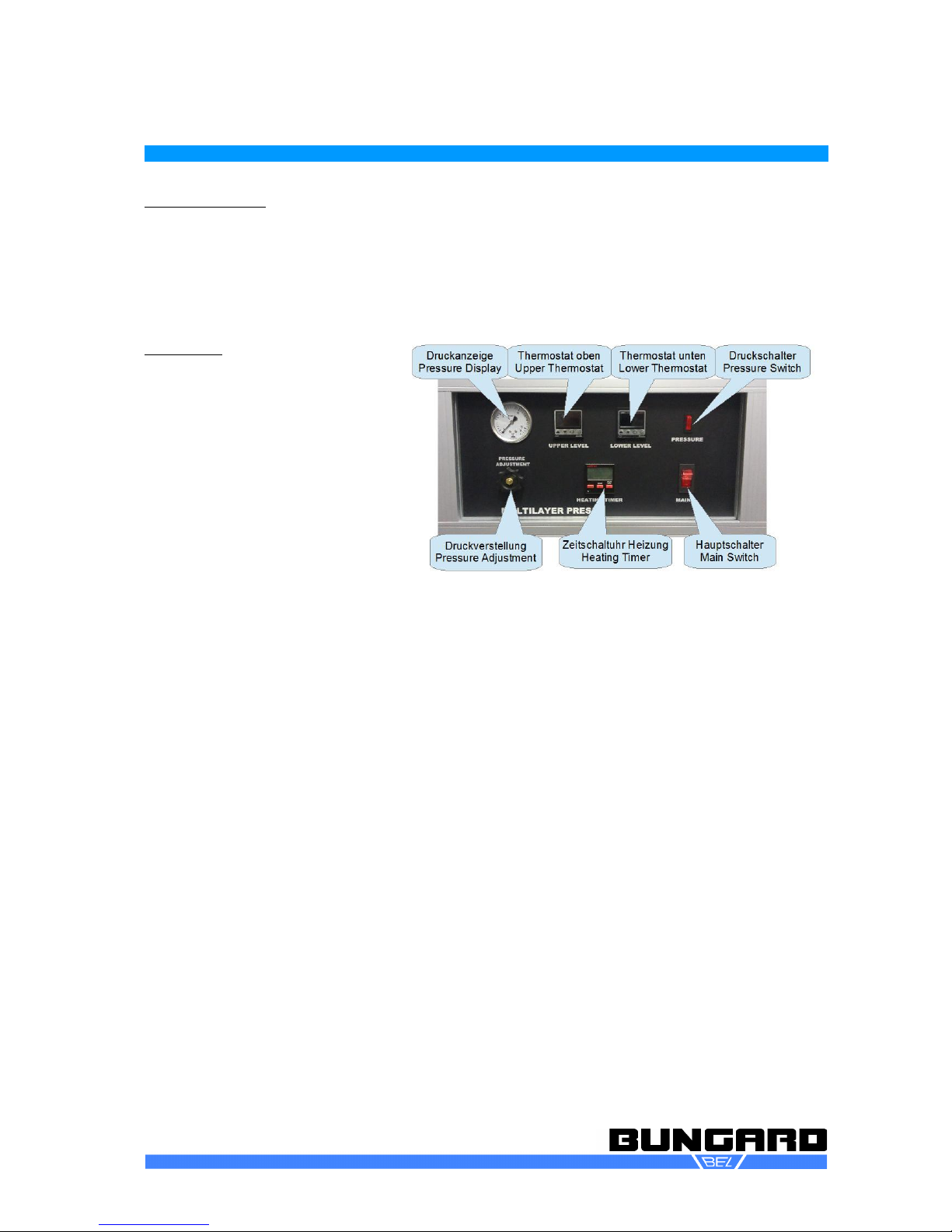
Switch on the power switch (MAINS
also serves as emergency stop, right
in the control panel). The compressor
starts.
Switch on the pressure by pressing
PRESSURE (compressor might re-
start).
On the hand wheel at the bottom left,
set the desired pressing pressure.
This depends on the material type,
age of the prepregs and most import-
ant: the size of your press pack. For an overview, see Printing Preferences. For material from the
RMP starter set with a press package size of 250 x 350mm (RMP210) set as standard 12 bar (for
the RMP3545 and press package size 350x450 is 8 bar).
Set the desired pressing time at the timer. After pressing PROG, the hour digits flash. With + or –
you can change the value. If you press PROG again, the minutes digits flash, then the seconds di-
gits flash. After the 4th press of PROG the normal display reappears and you can start the press
cycle by pressing - (Start / Stop). For material from the RMP Starter Set, the default time is 90
minutes (1:30:00).
Only after the pressing cycle is started, the temperature controls light up. The green display value
corresponds to the current heating-up specification (TARGET TEMPERATURE). The upper, red
value represents the currently reached temperature (CURRENT TEMPERATURE). To change the
preset temperature: Press MODE and then the arrow keys to set the desired heating temperature,
for example to 155 ° C as shown in this figure. Then press the button (MODE) again to save the se-
lected value. Heating starts with a pre-set ramp of 6 ° C / minute. After the set time has elapsed, the
heating will switch off and the fans will automatically switch off to cool down.
If you set higher temperatures than 175 ° C, you have to switch on the additional fans manually at
the beginning of the pressing cycle, so that the environment of the heating plates does not overheat.
Let the press stack cool sufficiently before removing it or wear appropriate protective gloves.
ungard Elektronik GmbH & Co. KG, Rilkestraße 1, 51570 Windeck – Germany
Tel.: +49 (0) 2292/9 28 28 - 0, Fax: +49 (0) 2292/9 28 28 - 29, E-mail: [email protected]

manual-rmp210-rmp3545-en-18 Page 6 / 16
Intended Use
The multilayer presses RMP 210 and RMP 3545 are used for the production of multilayers in an in-
dustrial-type equivalent frame.
All other applications require our written consent or at the user's own risk.
Safety Regulations
General
Please read the following text carefully and pay particular attention to the instructions on work safety
and on commissioning.
Please keep these instructions carefully. It contains instructions that are also important for later
maintenance or cleaning work.
The machines are not intended for integration or interconnection with other machines or equipment.
They may only be operated in rooms equipped for this purpose and only operated by qualified spe -
cialist staff. Children and pets are to be kept away!
Transport
Only use suitable lifting and transport equipment such as forklift trucks or pallet trucks. Secure the
machine against slipping / tilting. Attention, high center of gravity!
Transport machine only vertical! Do not carry horizontal by any means!
Installation site
The machine must stand level and there must be sufficient space for operation and maintenance.
The installation environment is critical to the trouble-free work with the RMP. You must therefore
pay special heed on a dust-free room and an atmosphere free of corrosive vapours to ensure
proper functioning.
Electrical connection
The machine is manufactured using tested parts in accordance with the usual electrical safety regu-
lations. However, this does not relieve the user of his duty of care when handling electrically oper -
ated devices.
The red main switch disconnects the machine from the power supply. We assume a proper building
installation including ground earth, current breaker (RCC ) and suitable fuses.
After completing the work, always turn off the main switch.
efore carrying out any work on the machine (cleaning, etc.), switch off the machine and pull out the
mains plug.
Work safety
The machine is equipped with a door safety switch. When the door is opened, the compressed air
for the press is deactivated.
This can destroy your multilayer circuit, but it is an important security feature of this machine.
Please check the function of the position switch regularly.
Machine may only be used with press plates in the press unit.
Personal protective equipment
When handling hot parts wear protective gloves. The safety instructions of the manufacturer or the
safety instructions of the supplier must be observed.
Temperature
ungard Elektronik GmbH & Co. KG, Rilkestraße 1, 51570 Windeck – Germany
Tel.: +49 (0) 2292/9 28 28 - 0, Fax: +49 (0) 2292/9 28 28 - 29, E-mail: [email protected]

manual-rmp210-rmp3545-en-18 Page 7 / 16
If the machine is heated higher than 175 ° C, a cooling fan (on the back of the machine) must be
manually switched on to cool the periphery.
Pay attention to suitable materials to avoid fire and related financial losses.
Continue to ensure suitable pressing temperatures to prevent burning of the printed circuit board
material and thus the possible formation of toxic and hazardous gases.
Allow the machine to cool down to a maximum of 50 ° C (approx. 30 - 45min) to avoid severe skin
burns when removing it, or wear suitable gloves.
At temperatures above 200 ° C, purely optical colour changes of the press plates may occur.
These do not represent any technical defects.
Exhaust
Extracting the room air in the area above the machine body is recommended with regards to
possible PC gas emissions. The need for extraction depends on the materials used and the
temperatures set.
Pressure
efore the compressor starts after switching on the machine, remove all parts from the press
plates, which could damage the machine or cause it to burst and can be propelled out of the
machine.
Machine must not be operated without the two 10 mm press plates!
Compressor
WHILE THE COMPRESSOR IS RUNNING, DO NOT OPEN THE MACHINE OR OPEN THE
DOOR TO THE PRESS ROOM.
Composition
Presskammer
Press compartment
edieneinheit
Operating panel
vorne Lagerraum
hinten Kompressor
front storage
back compressor
ungard Elektronik GmbH & Co. KG, Rilkestraße 1, 51570 Windeck – Germany
Tel.: +49 (0) 2292/9 28 28 - 0, Fax: +49 (0) 2292/9 28 28 - 29, E-mail: [email protected]

manual-rmp210-rmp3545-en-18 Page 8 / 16
Setup
The machine is delivered in a special wooden packaging. Please first check the condition of the
packaging upon receipt of the goods. Only acknowledge receipt of the goods by the forwarder as
okay if the packaging is in perfect condition. Otherwise this will endanger any claims to the transport
insurance.
If you notice damage only when unpacking the machine, please report them as concealed damage
also immediately in written from to the forwarder, your transport insurance and also to us.
To unpack the machine, first remove the side and top boards. The machine will then stand in front of
you on a pallet.
Only use suitable lifting and transport equipment such as forklift trucks or pallet trucks. Secure the
machine against slipping / tilting. Attention, high center of gravity!
Transport machine only vertical! Do not carry horizontal by any means!
The machine must stand level and there should be sufficient space for operation and maintenance.
Lock the rollers before first use.
Clean the machine of any transport contamination.
Connect the machine to the electrical supply indicated on the machine plate. If necessary, consult a
qualified electrician (RMP3545).
Perform a test run. Make sure that the two press plates are correctly in the press chamber.
The main switch on the right side of the front plate also serves as an emergency stop switch.
Turn on the device above. The compressor will start now.
The machine is equipped with a special compressor located in the rear body of the machine. You
can reach it by unscrewing the rear wall of the device (under the device Mains plug).
ATTENTION: OPEN THE MACHINE'S ACK ONLY AFTER YOU HAVE PULLED THE POWER
PLUG. DANGER!
efore starting the compressor, remove all parts from the press plates, which could damage the ma -
chine or burst and be thrown out of the machine.
ungard Elektronik GmbH & Co. KG, Rilkestraße 1, 51570 Windeck – Germany
Tel.: +49 (0) 2292/9 28 28 - 0, Fax: +49 (0) 2292/9 28 28 - 29, E-mail: [email protected]

manual-rmp210-rmp3545-en-18 Page 9 / 16
Pressure setting
As soon as you press the "PRESSURE" button, the RMP drives the press plates together. Since this
requires compressed air, the compressor will start again for about 2-3 minutes.
DANGER:
WHILE THE COMPRESSOR IS RUNNING, DO NOT OPEN THE MACHINE OR OPEN THE
DOOR TO THE PRESS ROOM.
The pressure is adjusted via the hand wheel on the front of the device.
For the correct pressure setting, please observe the processing instructions of the board material
manufacturer. As a guideline, please set a pressure of 12 tons / m² = 12 bar for a plate of
250x350mm².
Details about the pressure setting can be found in the appendix.
Timer
The timer controls the heating and cooling sequence of the
RMP 210.
The set time resembles the complete heating time including the
heating up sequence (you can calculate the approximate heat-
ing up time with the difference between set temperature minus
current temperature divided by 6 ° C / min. After the set total
time has elapsed, the heater is switched off and the cooling
phase is started when the cooling fans are switched on. To re-
set the timer, please press all 3 buttons for about 4 seconds.
Safety rules timer
Installation and connection may only be carried out by a quali-
fied electrician! Otherwise there is a risk of fire or electric
shock!
Only connect a voltage and frequency indicated on the rating
plate / timer!
Interventions or changes to the timer will void the warranty!
The timer must be installed in such a way that unusually strong interfering radiation may not affect
the function!
Key functions
[ PROG ] Selects between hours, minutes and seconds.
[ + ] Increments the selected time range.
[ - ] Decrements the selected time range.
[ RESET ] Resets to start time.
[ START/STOP ] Starts and stops the countdown.
Setting the time
•� Press the [ PROG ] button once.
� This will cause the hour digit to flash.
� Using the [+] [-] keys to set the desired amount of hours required.
� Repeat the process to set minutes and seconds.
� When keeping keys [+] or [-] depressed, the flashing digit will change upwards or downwards.
� Please note: After starting the countdown, the key [PROG] is without function until counting is fin-
ished.
Operating the timer
Pressing the [START/STOP] button activates the relay and the set time begins to count
down in one second steps.
ungard Elektronik GmbH & Co. KG, Rilkestraße 1, 51570 Windeck – Germany
Tel.: +49 (0) 2292/9 28 28 - 0, Fax: +49 (0) 2292/9 28 28 - 29, E-mail: [email protected]

manual-rmp210-rmp3545-en-18 Page 10 / 16
If the [START/STOP] button is pressed during the countdown period, the relay will
de-energize and time remaining is shown on the display.
The timer can also be started and stopped from the external connections.
When the set time reaches zero the unit emits an audible signal, the relay de-energizes and
the set time is indicated on the display.
Please note: If the [START/STOP] button is pressed and the time is zero, a bell symbol is
shown on the display and the relay will energize. Pressing the button again will de-energize
the relay.
Resetting to the time
Pressing the [RESET] button will set the time back to the start time.
Time reset
Pressing all three buttons together will set time to zero.
Total Reset
Press and hold down all three buttons for approx four seconds.
Data Storage on Loss of Power
On loss of power the count own will stop an the relay e-energize. The time remaining will
be store .
When power is resumed the remaining time will be shown and the timer will need to be restarted.
Setting the heater
The upper and lower heating levels can be
programmed separately.
oth thermostats are set to a maximum oper-
ating temperature of 250 ° C.
The heating rate is programmed at the fact-
ory with 6°C/min, but is in principle adjustable
to other values. Please contact us for the ori-
ginal instructions for the thermostats.
The green display value corresponds to the
current heating-up specification (TARGET).
The upper, red value of the respectively reached heating temperature (CURRENT).
Adjustment of the default temperature:
Press the button (MODE) and then the arrow keys to set the desired heating temperature, for ex-
ample to 175°C as shown in this figure.
Then press the button (MODE) again to save the selected value. The heating up can start now.
The thermostat has a "soft" heating control, which should avoid “overshooting” the set temperature.
For this reason, the temperature is ramped up gradually to the set default value.
The LED (OUT) indicates whether the heater is on or off.
The temperature to be set depends on the specifications of the material manufacturer and on the
gelling temperatures of the prepregs, as well as on the age of the prepregs.
ATTENTION: If the set temperature is too low or the process time too short, this can lead to rejects
and delamination. oth destroy the multilayer circuit.
ungard Elektronik GmbH & Co. KG, Rilkestraße 1, 51570 Windeck – Germany
Tel.: +49 (0) 2292/9 28 28 - 0, Fax: +49 (0) 2292/9 28 28 - 29, E-mail: [email protected]

manual-rmp210-rmp3545-en-18 Page 11 / 16
Wor process
The workflow described here is a process pattern. It can and must be adapted to the specification of
the prepreg manufacturer and to the layer specification.
a) If you do not use floating press technology (only possible with 4-layer multilayers), it is best
to pin-lock the plates outside the press area to align the layers correctly. To do this, drill all
layers and also use these holes as registration marks in the film. We recommend cutting the
prepregs smaller than the registration mark spaces to prevent resin from flowing into the re-
gister marks holes.
b) Place your press stack between the press plates.
c) Protect the press plates from sticking by kraft paper or Tedlar foil (release foil). Pay attention
to suitable materials to avoid a fire and thus substantial financial losses.
d) Continue to ensure suitable pressing temperatures in order to avoid burning of the printed
circuit board material and thus the possible formation of toxic and hazardous gases.
e) Set the pressing pressure for a plate from 210x300mm² to 12 bar (RMP3545 for plate 330 x
420mm² to approx. 8 bar).
f) For normal FR4 prepregs set a temperature of 155 - 175 ° C.
g) activate the heater.
h) a normal press cycle with FR4 depending on start and take-out temperature between 1 and
2 hours (according to type of pre-press and age of the prepregs).
i) Allow the machine to cool to a maximum of 50 ° C (approximately 30-45 minutes) to avoid
severe skin burns when removing, or use suitable gloves.
j) In no case should the plate material be removed at more than 100 ° C. The resin will still be
in Gel -condition and the stack could delaminate.
k) Take the final stack out of the machine and remove the pinning.
The whole process takes up to 3 hours. The raw format of the plates generally changes from
250x350 mm to 210x300mm² (due to the flow behavior of the resin / keyword: poor resin).
If you take appropriate measures to ensure that the plate stack comes out of the oven at a temperat-
ure of 100 ° C, you can reduce the process times to half an hour. This adjustment is solely the re -
sponsibility of the supervisor and we disclaim all liability.
ungard Elektronik GmbH & Co. KG, Rilkestraße 1, 51570 Windeck – Germany
Tel.: +49 (0) 2292/9 28 28 - 0, Fax: +49 (0) 2292/9 28 28 - 29, E-mail: [email protected]

manual-rmp210-rmp3545-en-18 Page 12 / 16
Composition of Press Stac
You can press up to 4 Layers in floating technique. Add reference holes into your inner layers
and adjust your layouts according to these holes.
Reference holes can be inserted into your layout with the help of IsoCam and can be drilled
with the ungard CCD.
Cut your prepregs and your outer layers smaller (as seen in the upper picture), so the resin of
the boards will not flow into the reference holes during the press cycle. You will need these
reference holes later on to register your pcb again for drilling on the CCD.
If your pcb is smaller than the press area of the machine (250 x 350 mm), we recommend to
adapt the pressure according to this formula:
PA = (PW x AW) / AA
PA = desired pressure for your pcb in bar
PW = machine pressure RMP 210) in bar
AW = press area of machine (250 x 350 mm = 8.75 dm² = constant)
AA = press area of your pcb in dm²
Example:
If you want to press a pcb with 120 x 120 mm with a pressure of 16 bar, please adjust formula:
(PA x AA) / AW= PW
(16 bar x 1,44 dm²) / 8.75 dm² = 2,63 bar
Set this pressure at the machine. For small pcbs we generally recommend to panelize the pcb
and so increase the press area.
ungard Elektronik GmbH & Co. KG, Rilkestraße 1, 51570 Windeck – Germany
Tel.: +49 (0) 2292/9 28 28 - 0, Fax: +49 (0) 2292/9 28 28 - 29, E-mail: [email protected]
Copyright by ungard Elektronik GmbH & Co. KG
Innenlage/Inner Layer
Außen-/Innenlage
Top/ ottom-Layer
Prepreg
Referenzlöcher ohne Nieten !
Reference holes without Rivets !

manual-rmp210-rmp3545-en-18 Page 13 / 16
If you want to press more than 4 layers, it is necessary to fix all layers with reference pins
to prevent the layers from moving during the press cycle.
Again you can add reference holes into your pcb with IsoCam and drill them with the
ungard CCD.
Reference rivets D3.0 x 5.4 mm can be obtained from ungard in packages of 100 rivets.
These rivets have to be mounted outside of the press area as in the upper picture, so they
can be easily removed after pressing.
See picture 3 for a sectional view on a press stack. The press sheets protect the press
plates from mechanical damage and the separation foil protects both press sheet and
press plate from contamination with resin
ungard Elektronik GmbH & Co. KG, Rilkestraße 1, 51570 Windeck – Germany
Tel.: +49 (0) 2292/9 28 28 - 0, Fax: +49 (0) 2292/9 28 28 - 29, E-mail: [email protected]
Copyright by ungard Elektronik GmbH & Co. KG
Innenlage/Inner Layer
Außenlagen / Top/ ottom-Layer
Prepreg
Hinten/Rear
Türöffnung / Door
Referenzlöcher mit Nieten !
Reference holes with Rivets !
Pressplatten u. -bleche
Press plates and sheets
Copyright by ungard Elektronik GmbH & Co. KG
Innenlage/Inner Layer
Außenlagen
Top/ ottom-Layer
Prepreg
Pressplatten/Press Plates
Pressbleche/Press Sheets
Trennfolie/Separation foil
Pressbleche/Press Sheets
Verstiftung mittels Referenznieten
Fixation with reference rivets

manual-rmp210-rmp3545-en-18 Page 14 / 16
Cleaning and maintenance
The machine itself is maintenance free. When pressing, make sure that any escaping resin is
caught by the Teflon films. Press plates can be cleaned with brushing machines and special
solvents.
Spare part list
80173 Startpaket Multilayerpresse
RMP 210, 100
consumables starter
kit for Multilayer Press
RMP
80173-2 Trennbleche 250x350 mm Metal separator
sheets 250x350mm
80173-3 TEDLAR Entformungsfolie
250x350mm
TEDLAR separation
foil 250x350mm
6000 K2983.01-230 Magnetentlastungsventil Solenoid valve
6000 A 1362 Druckregler 1/4” 0 - 16 bar Pressure reducer 1/4”
0-16 bar
6000 410339 Relais für RMP210 Relays for RMP210
6000 K2590-16
6000 MP671140
6000 MP671140a
ungard Elektronik GmbH & Co. KG, Rilkestraße 1, 51570 Windeck – Germany
Tel.: +49 (0) 2292/9 28 28 - 0, Fax: +49 (0) 2292/9 28 28 - 29, E-mail: [email protected]

manual-rmp210-rmp3545-en-18 Page 15 / 16
Guarantee
All machines perform a functional and continuous operation test before delivery. On the machine,
we grant our customers a bring-in-warranty of 12 months from the date of purchase with regard to
accuracy in material and workmanship. We provide a warranty of our choice by replacing defect -
ive parts or by repairing the machine in our house. Old parts become our property.
Disclaimer of Warranty
ungard GmbH & Co. KG reserves the right to make any changes or improvements to any machine or
machine specification it deems necessary at its sole discretion, and assumes no obligation to imple -
ment such changes in previously sold machines.
ungard products and services are subject to the then prevailing prices and terms. These prices and
conditions are subject to change.
The information in this document is subject to change and does not constitute any representation on the
part of ungard.
This manual contains information for the RMP210 and the RMP3545 and is the translation of the ori -
ginal instructions.
Conditions of sale and delivery: These are available to the buyer at the latest when the contract is ful -
filled. We do not warrant or accept any liability for damage to material or personal injury caused by any
of the following:
Improper use of the machine
Incorrect setup, commissioning and operation of the machine or inadequate service
Use of the machine with damaged safety devices
Non-compliance with the manual regarding transport, storage, assembly, installation and service of the
machine
Unauthorized changes to the machine
Improper or incomplete repairs
Destructive forces on the machine due to foreign bodies or strong external use of force
Use of non-original spare parts
Wear parts are excluded from warranty.
We can not accept any replacement or follow-up claims arising from damage or destruction of work -
pieces machined in the machine, since the parameters influencing the operation of the machine are
largely beyond our control.
This applies mutatis mutandis to claims arising from damage to objects, buildings and people and the
environment.
All information has been compiled with care. We reserve the right, however to errors and technical
changes, even without notice,
Operation in an aggressive, dusty, damp, extremely hot or potentially explosive environment is at the
user's own risk and responsibility.
The user must take care of appropriate precautions and protective equipment. Any liability for damage
caused by operation in such an environment is hereby expressly excluded.
Copyright
© 2018 ungard Elektronik GmbH & Co. KG
ungard Elektronik GmbH & Co. KG, Rilkestraße 1, 51570 Windeck – Germany
Tel.: +49 (0) 2292/9 28 28 - 0, Fax: +49 (0) 2292/9 28 28 - 29, E-mail: [email protected]

manual-rmp210-rmp3545-en-18 Page 16 / 16
Pressing Preferences
RMP3545 Grafik Druckumrechnung
4 bar
= 40 Newton / cm²
Compensator effective area = ca. 2091 cm²
Force = 40 Newton/cm² x 2091cm² = 83640 N
Force = 8,3 tons
Force on pcb =
8,3 tons
PC Area A4=210 x 297mm²= 630 cm²
Pressure on PC =
83640 N / 630= 133N/cm²
=
13,3 bar
8,3 tons
Compensator
=
Press Cylinder
PC
Pressure 1 bar = 10 N/cm²
in Newton In Kilo In Tonnen
1 20910 2091,0 2,091 2,4 13,1 1,3 3,3
2 41820 4182,0 4,182 4,8 26,1 2,7 6,6
3 62730 6273,0 6,273 7,2 39,2 4,0 10,0
4 83640 8364,0 8,364 9,6 52,3 5,3 13,3
5 104550 10455,0 10,455 11,9 65,3 6,6 16,6
6 125460 12546,0 12,546 14,3 78,4 8,0 19,9
7 146370 14637,0 14,637 16,7 91,5 9,3 23,2
8 167280 16728,0 16,728 19,1 104,6 10,6 26,6
9 188190 18819,0 18,819 21,5 117,6 11,9 29,9
10 209100 20910,0 20,910 23,9 130,7 13,3 33,2
11 230010 23001,0 23,001 26,3 143,8 14,6 36,5
12 250920 25092,0 25,092 28,7 156,8 15,9 39,8
13 271830 27183,0 27,183 31,1 169,9 17,3 43,1
14 292740 29274,0 29,274 33,5 183,0 18,6 46,5
in Newton In Kilo In Tonnen
1 8300 830,0 0,830 0,9 5,2 1,3
2 16600 1660,0 1,660 1,9 10,4 2,6
3 24900 2490,0 2,490 2,8 15,6 4,0
4 33200 3320,0 3,320 3,8 20,8 5,3
5 41500 4150,0 4,150 4,7 25,9 6,6
6 49800 4980,0 4,980 5,7 31,1 7,9
7 58100 5810,0 5,810 6,6 36,3 9,2
8 66400 6640,0 6,640 7,6 41,5 10,5
9 74700 7470,0 7,470 8,5 46,7 11,9
10 83000 8300,0 8,300 9,5 51,9 13,2
11 91300 9130,0 9,130 10,4 57,1 14,5
12 99600 9960,0 9,960 11,4 62,3 15,8
13 107900 10790,0 10,790 12,3 67,4 17,1
Compressor
pressure in
bar
Gravitational force on Compensator area RMP 3545:
effective area 2091cm² Pressure in bar at
875 cm² (Press plates
RMP210 250x350mm)
Pressure in bar
at 160 cm² (Eu-
rocar
100x160mm)
Pressure in bar at
1575 cm² (Press plates
RMP 3545
450x350mm)
Pressure in
bar at 630 cm²
(Din A 4 210 x
297)
RMP210
normal
Compensator with nominal wi th 300mm has effec-
tive area of 830 cm²
Compressor
pressure in
bar
Gravitational force on Compensator area RMP 210: ef-
fective area 830 cm² Pressure in bar at
875 cm² (Press plates
RMP210 250x350mm)
Pressure in bar
at 160 cm² (Eu-
rocar
100x160mm)
Pressure in bar at
630 cm² (Din A 4 210 x
297)
ungard Elektronik GmbH & Co. KG, Rilkestraße 1, 51570 Windeck – Germany
Tel.: +49 (0) 2292/9 28 28 - 0, Fax: +49 (0) 2292/9 28 28 - 29, E-mail: [email protected]
Other manuals for RMP 210
1
This manual suits for next models
1
Table of contents
Other Bungard Power Tools manuals
Popular Power Tools manuals by other brands

GREAT PLAINS
GREAT PLAINS RCB6610 Operator's manual

Lortone
Lortone 3-1.5B Instructions and parts list

Parkside
Parkside PAMFW 10.8 A1 Operation and safety notes

Metabo
Metabo KHE 55 operating instructions

Mafell
Mafell pss 3000 Operating instruction

Pattfield Ergo Tools
Pattfield Ergo Tools E-HP 2000 operating instructions