9
SERVICE
This section provides procedures for testing and
replacing various major components used in this dis-
penser should service become necessary. Refer to
Troubleshooting for assistance in determining the cause
of any problem.
Component Access
WARNING – Disconnect the dispenser from the power
source before the removal of any panel or the replace-
ment of any component. The limit thermostat, liquid level probe, tank heater,
and temperature sensor are located at the top of the
dispenser. Access is gained by removing the top lid,
attached with three 4-40 slotted-head screws.
WARNING – Inspection, testing, and repair of electrical
equipment should be performed only by qualified ser-
vice personnel. Disconnect the dispenser from the
power source when servicing, except when electrical
tests are required and the test procedure specifically
states to connect the dispenser to the power source.
Contactor ............................................................ 17
Limit Thermostat ................................................ 10
Liquid Level Board .............................................. 15
Safety Overflow Switch ....................................... 11
Solenoid Valve .................................................... 12
Tank Heater ........................................................ 13
Control Thermostat............................................. 14
O
N
CAUTION
!
FailureToComplyVoidsWarranty!
HotWater Systems –Water Tank Will Fill
AutomaticallyWhen Unit Is ConnectedToPower!
CoffeeBrewers–Fill The WaterTank In
AccordanceWithThe Installation Instructions!
DONOT
Turn On The Tank Heater Switch
Until Water Comes From Opened Faucet!
W
O
N
OFF
ON
STOP
READNOTICE
DISCONNECTFROMPOWERSOURCE
BEFOREREMOVALOFANYPANELOR
REPLACEMENTOFANYCOMPONENT!
WARNING
!
O
N
CAUTION
!
FailureToComplyVoidsWarranty!
HotWater Systems–Water Tank Will Fill
AutomaticallyWhen Unit Is Connected ToPower!
CoffeeBrewers –Fill TheWater TankIn
AccordanceWith TheInstallation Instructions!
DONOT
Turn On The Tank Heater Switch
Until Water Comes From Opened Faucet!
HAZARDOUS
VOLTAGE
DISCONNECTFROM
POWERSOURCE
BEFOREREMOVING!
WARNING
O
N
ON
STOP
READNOTICE
Fillwatertankbeforeturning-on
thermostatorconnectingappliance
topowersource.
Donotusenearcombustibles.
Follownational/localelectricalcodes.
Electricallygroundthechassis.
Useonlyonaproperlyprotected
circuitcapableoftheratedload.
FAILURETOCOMPLYRISKSEQUIPMENT
DAMAGE,FIRE,ORSHOCKHAZARD
READTHEENTIREOPERATINGMANUAL
INCLUDINGTHELIMITOFWARRANTYAND
LIABILITYBEFOREBUYINGORUSINGTHISPRODUCT
THISAPPLIANCEISHEATEDWHENEVER
CONNECTEDTOAPOWERSOURCE
00831.0000A5/88©1988BUNN-O-MATICCORPORATION
WARNING
!
Thisequipmentistobeinstalledto
complywiththeBasicPlumbingCodeof
theBuildingOfficialsandCode
AdministratorsInternational,Inc.(BOCA)
andtheFoodServiceSanitationManual
oftheFoodandDrugAdministration(FDA).
DISCONNECTFROMPOWERSOURCE
BEFOREREMOVALOFANYPANELOR
REPLACEMENTOFANYCOMPONENT!
WARNING
!
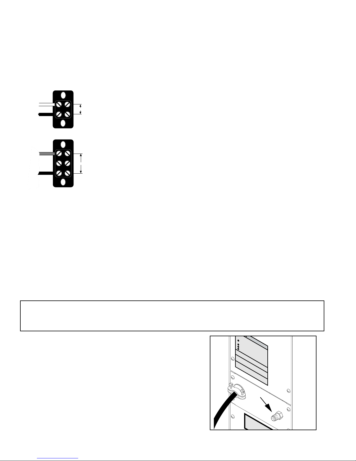
The check valve, safety overflow switch, solenoid
valve, overflow tube temperature sensor, control ther-
mostat and terminal block are located at the rear of the
dispenser. Access is gained by removing the upper and
lower rear panels. The upper is attached with six 8-32
slotted-head screws. The lower is attached with four
8-32 slotted-head screws. The middle panel must not
be removed from the dispenser.
P1770
P1770
10267 011599