B-Smart-Lock Keypad Outdoor | 06-2019 02 - AN/ DSW | English | 3
Dimensions 68.9 x 68.9 x 24 mm
Power supply Lithium battery 3V, CR123A
Service life:
45,000 locking cycles
Permissible temperature 0°C –40°C
(no formation of condensation)
Protection class IP 54
No. of possible codes 999.999
Code length 4 or 6 digits
Programming Freely selectable PIN
Fixed assigned PIN
Material Casing: plastic
(RoHs proved)
Keypad: silicon
Keypad core: zamac
Colour Grey or user specific
Locking direction L, R
Lock attachment Raised countersunk screw
5 x 16,Torx 20
Latch Plastic bolt
Technical specifications
Mode: Freely selectable PIN (Multi User)
In this mode, a large number of users can use the lock. To ope-
rate the lock no specific PIN is required. The user enters a PIN of
choice (4- or 6-digits, depending on the programming) to close
and confirms this by pressing the hook key twice. The lock locks.
By re-entering this PIN, the lock will be opened again. After the
opening process, a new PIN can be used.
Mode: Fixed assigned PIN (Private PIN)
In this mode, a PIN is pre-set with which the lock can be ope-
rated. The user enters the PIN to close or holds down the hook
key for 2 seconds. The lock is opened by entering the stored
PIN. Up to 50 PINs can be stored at the same time. Each of these
PINs can re-open the lock, regardless of the PIN used to close it.
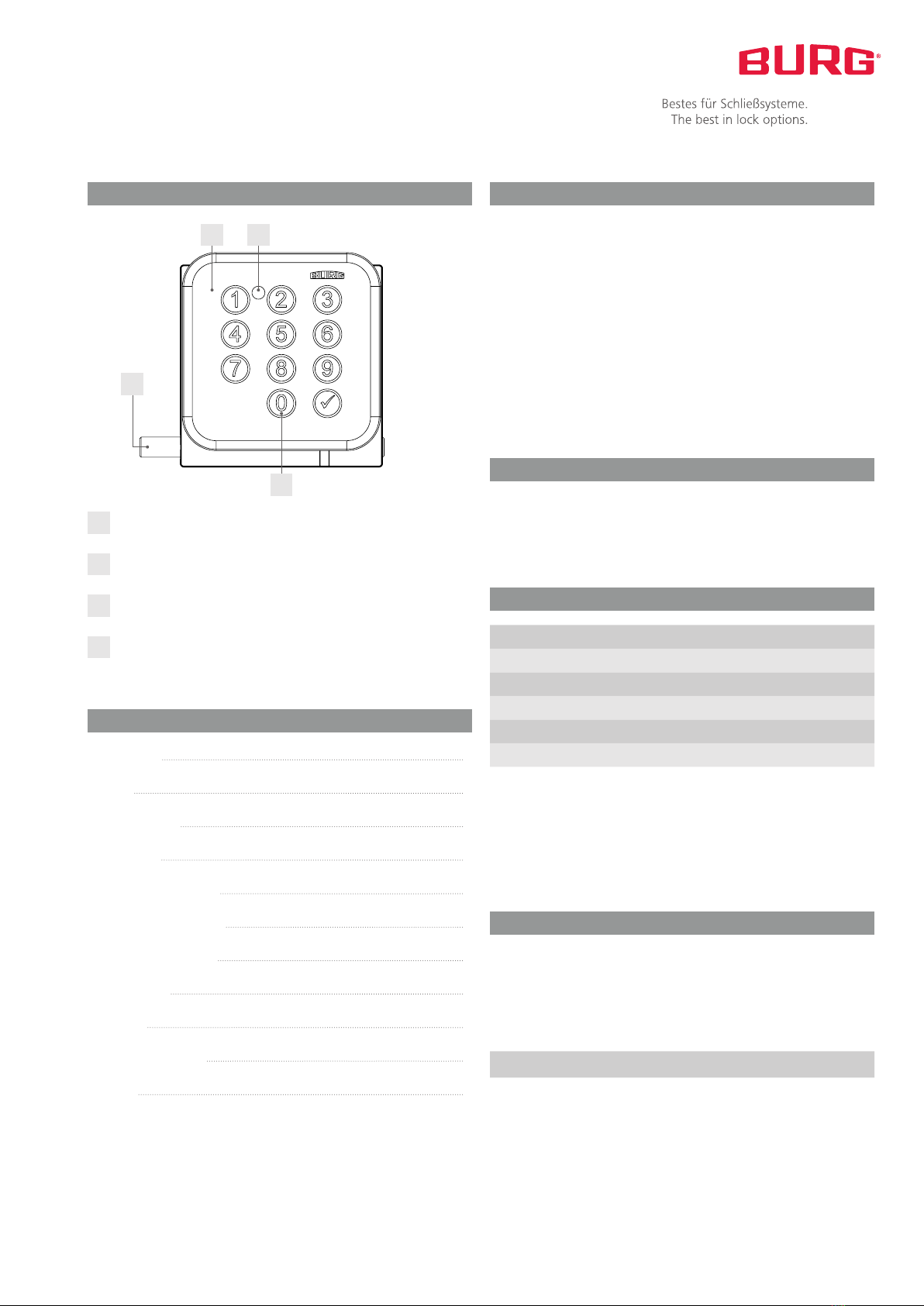
LED locking indicator
The LED flashing indicates that the lock is locked. If the lock is
in the open state, the LED will not flash. This feature is optional
and can be turned on or off.
Code re-enter
The code re-enter requires the PIN entry twice to engage the
lock. The second entry is used to confirm the first entry. The
lock locks only after this confirmation. Wait for the green LED
flashing before entering the code the second time. The lock can
be opened entering the PIN once. This feature is optional and
can be turned on or off.
Battery warning
The lock will notify if the battery capacity falls below a certain
limit. This will be announced in 2 stages. If the capacity falls be-
low the first level, the red LED lights flash for three seconds after
entering the PIN. If the capacity falls to a critical range, the lock
can only be locked or opened with the master code.
Note: We recommend changing the battery after the first war-
ning.
Each step of the configuration is completed with double LED
flashing. It is absolutely crucial to wait for the flashing before
starting the next configuration step.
If you change the mode (Freely selectable PIN Fixed assi-
gned PIN or Fixed assigned PIN Freely selectable PIN) all func-
tions are reset to their default settings (see „Default settings“).
This does not apply to the master code.
If the configuration step is not carried out correctly, the lock
signals this by flashing 8 times quickly.
Attention: After 3 wrong entries the lock will be disabled for 45
seconds. This is displayed with a red LED flashing every second.
Entering the master code stops the lock from being temporarily
disabled.
Important information Functional description