TwinPad | 12-2020 Rev. 03 | English | 6
Configuration 3Assign Master Card and User Card
a) Assign Master Card
Enter Master Code: Master Code + „“
Confirmation by a longer beep and flashing of the LED.
1. Hold the Master Card centered on the lock. A long
beep confirms the successful addition.
2. Continue if you want to add more Master Cards
(up to 3).
3. If finished wait until the LED stops flashing.
b) Assign User Card (Private Mode)
1. Hold the Master Card centered on the lock. Wait
for the beep and the LED to light up.
2. Hold the Master Card centered on the lock again,
until the LED starts flashing.
3. Hold the user card centered on the lock. A beep
confirms the successful addition.
4. Continue if you want to add more user cards (up to 27).
5. If finished wait until the LED stops flashing.
c) Delete User Card (Private Mode)
1. Hold the Master Card centered on the lock. Wait
for the beep and the LED to light up.
2. Hold the Master Card centered on the lock again,
until the LED starts flashing.
3. Hold the Master Card a third time on the lock and
the LED will flash quickly.
4. Hold the user card you want to delete on the lock.
A long beep confirms the successful deletion.
5. Continue if you want to delete more user cards.
6. If finished wait until the LED stops flashing.
To test if the user card was successfully deleted, hold the user
card centered on the lock. Three short beeps indicate that the
card is not added.
4Reset the lock to default settings
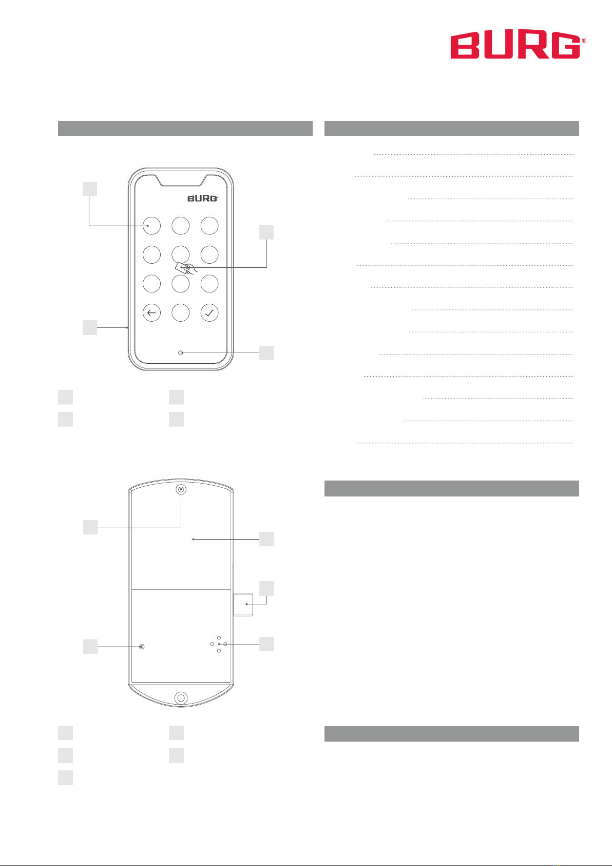
1. Slightly press the reset pin into the resethole on the
back of the back unit for one second.
2. Wait for the long beep. The long beep confirms the
successful reset.
Note: The lock remains in the set mode. All settings will be reset
to the default settings of the active mode. All user cards and
Master Cards will be deleted. The code and Master code will be
changed to default setting.
1Set the Mode
a) Private Mode (default setting)
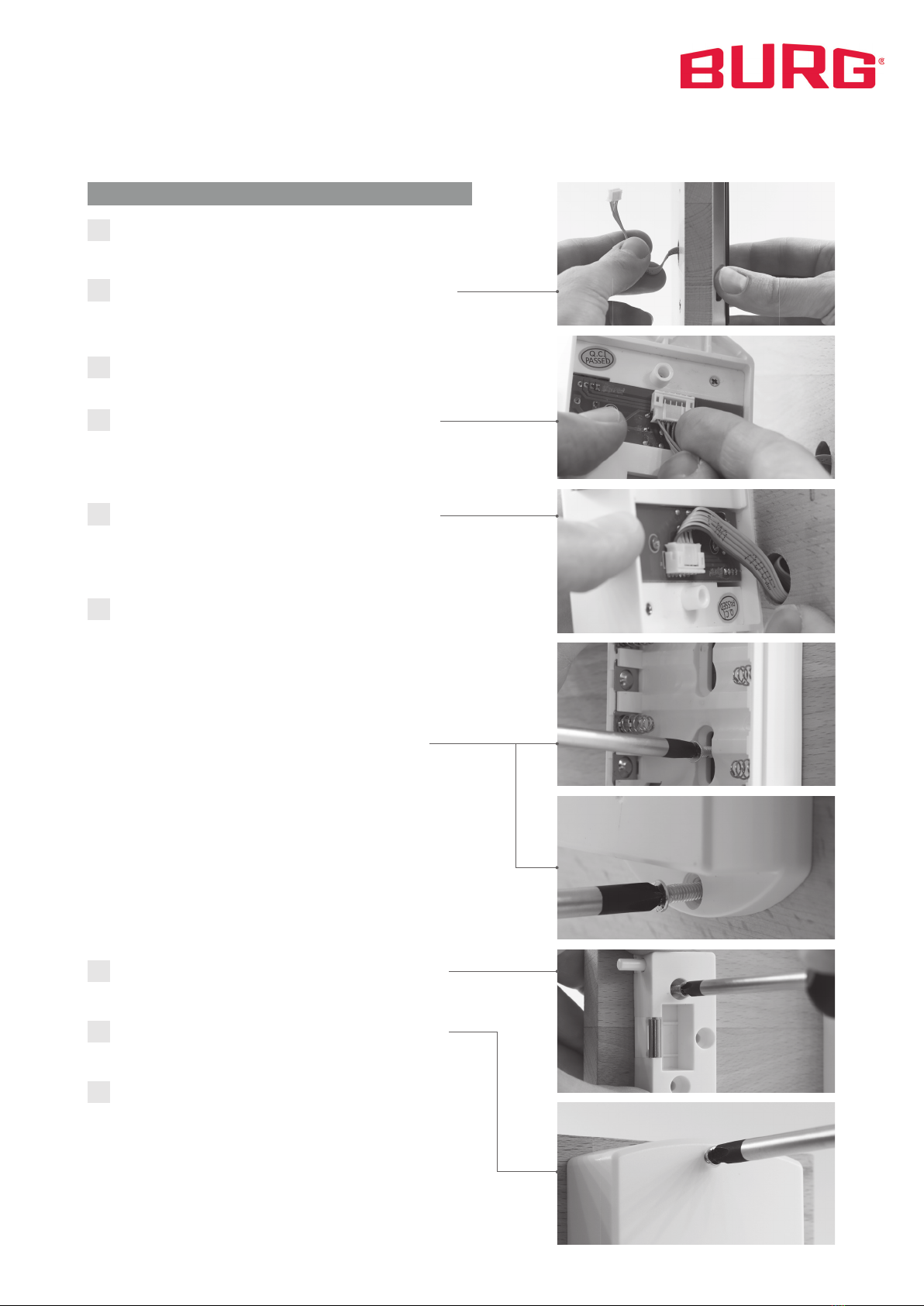
1. Open the battery compartment and remove one battery.
2. Slightly press the reset pin into the reset hole and keep
it pressed.
3. Reinsert the battery. When you hear a beep and the
locking bolt moves out, release the pin.
b) Multi User Mode
1. Open the battery compartment and remove one battery.
2. Slightly press the reset pin into the reset hole and keep
it pressed.
3. Reinsert the battery. When you hear two beeps and the
locking bolt moves in, release the pin.
Note: After switching the mode, the lock is in the default set-
tings of the mode to which it was changed.
2Set the Master Code and Code
a) Set the Mastercode (Private Mode/ Multi User Mode)
Enter Master Code: Master Code + „“
Confirmation by a longer beep and flashing of the LED.
Enter new Master Code: xxxx (xxxx)1+ „“
Confirmation by a longer beep.
Note: You can only store one Master Code. When a new Master
Code is stored, the active Master Code will be overwritten.
b) Set a User Code (Private Mode)
Enter Code: Code + „“
Confirmation by a longer beep and flashing of the LED.
Enter new Code: xxxx (xxxx)1+ „“
Confirmation by a longer beep.
Note: You can only store one code. When a new code is stored,
the active code will be overwritten.
c) Reset the User Code
Enter Master Code: xxxx (xxxx)
By entering the Master Code, the lock opens. In Multi User
Mode, the active code is deleted. In Private Mode, the code is
reset to the default setting (1234).
Code 1234
Master Code 934 716
Default Settings
1 4 to 8 digits