BURK Technology PlusConnect GatesAir Sigma User manual

Installation and Operation Manual REV D
PlusConnect™GatesAir Sigma
Installation and Operation Manual

Table of Contents
Introduction ................................................................................................................................................. 1
Compatibility ............................................................................................................................................... 1
Unpacking................................................................................................................................................... 2
Front Panel Indicators ................................................................................................................................ 2
Hardware Configuration.............................................................................................................................. 3
Installation .................................................................................................................................................. 5
Software Configuration............................................................................................................................... 6
Setting up Labels, Limits and Alarms..................................................................................................... 8
Creating a PlusConnect Custom View inAutoPilot ....................................................................................9
Operation.....................................................................................................................................................10
Troubleshooting...........................................................................................................................................11
Getting Help ..........................................................................................................................................11
Warranty.............................................................................................................................................. ..11
Copyright © 2015-2021 Burk Technology, Inc.

PlusConnect™ GatesAir Sigma Installation and Operation Manual 1
Introduction
This manual describes the PlusConnect™ GatesAir Sigma. The PlusConnect provides a connection
between the GatesAir Sigma transmitter series and the ARC Plus transmitter remote control
system. The PlusConnect reads transmitter parameters using a serial connection. The PlusConnect
then forwards real-time data to the ARC Plus via LAN, WAN, or Internet.
Monitor and control PlusConnect channelsvia:
•The front panel of the ARC Plus
•Web browser, using the built-in web interface on the ARC Plus
•Web-enabled mobile device, using the built-in mobile web interface on the
ARC Plus
•PC, using optional AutoPilot® software
•Telephone, using the optional ESI or RSI Speech Interfaces for the ARCPlus
The PlusConnect is part of the Plus-X family of Ethernet I/O products designed for the ARC Plus.
Important! The PlusConnect operates in conjunction with an ARC Plus system. Be sure to
complete configuration of the ARC Plus before adding the PlusConnect to the system.
Compatibility
Transmitter Compatibility
Model
Compatibility
PlusConnect GatesAir Sigma
All GatesAir Sigma transmitter models
Transmitter models, firmware versions and options are subject to change. Visit www.burk.com for
current information.
Installation Note
Even though you may operate the ARC Plus and PlusConnect on different subnets, Burk Technology
strongly recommends installing the PlusConnect on the same LAN as the ARC Plus. In a network failure,
an ARC Plus can only continue to monitor and control a PlusConnect on the same LAN. If the network
link between the units is not available, ARC Plus macros, alarm monitoring and telephone control will be
unavailable for the PlusConnect unit.

PlusConnect™ GatesAir Sigma Installation and Operation Manual 2
ARC Plus Compatibility
Before installing the PlusConnect, please verify that the ARC Plus firmware, AutoPilot software and
AutoLoad Plus software versions are current. Updates are available at www.burk.com.
Unpacking
The PlusConnect ships with the following:
PlusConnect unit
AC Power cord
10’ Shielded CAT5 cable
10’ DB9F to DB9F serial cable
Front Panel Indicators
Indicator
State
Description
Power LED
On
Power is on
Power LED
Off
Power is off
Link LED
On
ARC Plus to PlusConnect connection isgood
Link LED
Off
ARC Plus to PlusConnect connection is down
Front panel of the PlusConnect unit

PlusConnect™ GatesAir Sigma Installation and Operation Manual 3
Hardware Configuration
This step will link the PlusConnect to a specific ARC Plus unit and will identify the transmitter to which the
unit will be connected.
Important! This procedure will reset the PlusConnect to its default IP address: 192.168.0.100.
1. Connect your PC and the PlusConnect together using a cross-over Ethernet cable or network Hub.
2. Assign your PC to an available IP address on subnet 192.168.0.xxx (other than 192.168.0.100) with
the subnet mask setto255.255.255.0.
3. Connect the PlusConnect AC power cord and wait for the green Power LED to illuminate.
4. Use a paper clip or similar small object to press and hold the Config button on the rear panel of the
PlusConnect unit. Hold the button in until the Power LED begins to blink. The Power LED will stop
blinking when the unit has completed restoring default settings.
5. Enable Telnet on your Windows 7 or Windows 8 computer, if not already enabled, using the
following steps:
•Click Start > Control Panel
•Click Programs and Features
•Click Turn Windows features on or off
•In the Windows Features dialog box, check the Telnet Client check box
•Click OK. The system installs the appropriate files. This will take a few seconds to a
minute to complete.
6. Open a Telnet session to the PlusConnect at the address 192.168.0.100 (port 23).Using
Windows, you can launch Telnet by typing “telnet 192.168.0.100” from a commandprompt.
7. When prompted, enter the password for the PlusConnect.If a password has not been set yet you
will be asked to set it. The password cannot be set to “password”.

PlusConnect™ GatesAir Sigma Installation and Operation Manual 4
8. Telnet will display the main menu.
9. Enter the appropriate configuration settings for the following parameters:
To change a setting, enter the menu number for that setting and then press<Enter>.
#
Setting
Description
2
IP Address
The IP address you want to assign to the PlusConnectunit
3
Subnet
The subnet mask for your LAN
4
Gateway
The gateway for your LAN
7
ARC Plus IP Address
The IP address of your ARC Plus unit
8
Plus-X Port
The Plus-X port number configured on your ARC Plus (typically 45000)
9
Set Unit Name
The PlusConnect unit name
Once the settings have been saved, the PlusConnect can be connected to the target LAN. All future Telnet
sessions should use the newly configured IP address.

PlusConnect™ GatesAir Sigma Installation and Operation Manual 5
Setting the Password
Changing your password is strongly recommended. The PlusConnect password is used to access the Telnet
configuration menu. To change the password, use option #10: Set Password, then #99 to save the modified
password. The password cannot be set to “password”.
Uploading New Firmware
To upload new firmware to the PlusConnect, use option #12: Update Firmware. When prompted to start the
firmware upload, enter “Y” for yes. The system will respond with the followingmessage:
Download and install the Burk Firmware Loader (If not already installed)
1. If the Burk Firmware Loader is already installed on your computer, proceed to “Download the
PlusConnect GatesAir Sigma Firmware.”
NOTE: By default, only members of the Administrators group on a computer can install new software. If you do
not have the rights to complete all steps of this process, please contact your system administrator.
2. Go to www.burk.com/downloads, select the ARC Plus tab, then scroll down to the PlusConnect
section.
3. Download and install the Burk Firmware Loader.
Download the PlusConnect GatesAir sigma firmware
4. Go to www.burk.com/downloads and select the ARC Plus tab, then scroll down to the PlusConnect
section.
5. Download and save the PlusConnect GatesAir Sigma firmware file.
Allow Burk Firmware loader through Windows Firewall
6. Click Start >Control Panel and select Windows Firewall
7. Select Allow a Program or feature through Windows firewall
8. Select Allow another program
NOTE: If the Allow another program button is un-selectable, click the Change Settings button first to unlock
this.
9. Now click browse and search for the file C:\Program Files(x86)\Burk Technology\Burk Firmware
Loader.
10. Select BurkFirmwareLoader and click Open and then click Add
Run Burk Firmware Loader
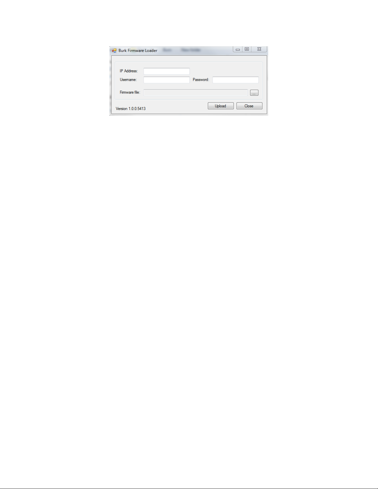
11.Click Start >All Programs>Burk Technology>Burk Firmware Loader and launch the program.
The dialog below will open.

PlusConnect™ GatesAir Sigma Installation and Operation Manual 6
12. Enter the IP Address, User Name and Password of the PlusConnect unit. Select the PlusConnect
firmware file that you previously saved
13.Click Upload.
14. A notification window will open when the upload is complete. Click OK
Verify upload of firmware
To verify the firmware version, open a new Telnet session to the PlusConnect unit and observe the
revision number that precedes the Telnet password prompt.
Installation
After entering the configuration settings, you are ready to install the PlusConnect in its permanent location.
Connect the Ethernet port on the PlusConnect unit to your LAN. Connect the female-female straight-through
DB-9 cable (provided) from the PlusConnect serial port to either J6 or J7, also called HP1 and HP2, on the Sigma
Transmitter.
To ensure that your transmitter is configured to interface with the PlusConnect, you should first verify
the following Sigma CD Transmitter software and firmware revisions:
GUI Program Software for Windows® - GUI Version 5.0.0 (or higher)
Main Controller Firmware - Version 3.0 (or higher)
Amplifier Interface Board Firmware - Version 1.11 (or higher)
IPA Module Firmware - Version 2.14 (or higher)
NOTE: To check the firmware revision levels on the transmitter see the Introduction section of the Sigma
Software manual, 888-2469-001.
The Sigma Main Controller password requirement must be deactivated to enable communication with the
PlusConnect. To accomplish this, set the S2 dipswitch on the transmitter Main Controller Board as follows:
• If the PlusConnect is being connected to J6 (HP1), set dipswitch S2 position 7 to ON
• If the PlusConnect is being connected to J7 (HP2), set dipswitch S2 position 8 to ON
Burk Firmware Loader dialog

PlusConnect™ GatesAir Sigma Installation and Operation Manual 7
To enable the Sigma serial port for connection to the PlusConnect, select System I/O board switches S4 and
S5 as shown in the image below from the GatesAir software instruction guide. Both S4 and S5 dipswitches
should only have positions 3 and 4 ON.
Now apply power to the PlusConnect unit and wait for the green Power LED to illuminate.
DIP Switch Settings for Direct Computer Connection

PlusConnect™ GatesAir Sigma Installation and Operation Manual 8
Software Configuration
Now that the PlusConnect is installed on the network and connected to the transmitter, you are ready to add
the PlusConnect to the ARC Plus site using AutoLoad Plus. AutoLoad Plus is included with the ARC Plus and
may be downloaded from www.burk.com.
Configuration involves:
•Adding the PlusConnect unit to the ARC Plus site
•Mapping PlusConnect parameters to unused ARC Pluschannels
Adding the PlusConnect Unit to the ARC PlusSite
In order for the ARC Plus to recognize the PlusConnect, the PlusConnect must be added to the ARC Plus site:
1. Open AutoLoad Plus and connect to the ARC Plus site to which you are adding the
PlusConnect.
2. Select that site from the Navigator pane on the left side of the window.
3. From the Edit menu, select Plus-X Devices to open the list of currently configured Plus-X Devices.
4. Click Add… to add the PlusConnect to the site. This opens the Plus-X Device dialog.
5. For Device type, select PlusConnect GatesAir Sigma. You may optionally change the description
for the PlusConnect. The description appearsin AutoLoad Plus to identify each PlusConnect
channel.
6. Enter the IP address and port number of the PlusConnect. These should be the same settings you
used when you configured the PlusConnect using Telnet.
Adding a Plus-X device in AutoLoad Plus

PlusConnect™ GatesAir Sigma Installation and Operation Manual 9
7. Check the Map the default set of channels box if you wish to automatically add themost
commonly used PlusConnect parameters to the ARC Plus (recommended).
8. Set Starting channel to the first unused channel in the ARC Plus.
9. Click OK on the Plus-X Device dialog, then click OK on the Plus-X Devices list. This will replace
unused ARC Plus channels with 39 PlusConnect status channels, 5 meters and 5commands. There
must be 39 consecutive unused channels, including the starting channel. You do not need to
have additional Integrated Input Units or Integrated Command Relay Units in orderto use these
channels.
10. Select File>Save to save the settings to the ARC Plus unit. Wait for the progress dialog to
complete.
11. Observe that the green Link LED illuminates indicating that the PlusConnect is communicating
with the ARC Plus unit.
Three additional custom view templates are available for use with the GatesAir Sigma. These custom view
templates are optimized for Sigma transmitters with one, two or three power amplifier cabinets. The names of
these specialized custom view templates are “PlusConnect GatesAir Sigma 1PA”, “PlusConnect GatesAir Sigma
2PA”and “PlusConnect GatesAir Sigma 3PA”, respectively.
Important! PlusConnect channels take the place of normal I/O channels. If a metering input, status input,
or command relay is connected to an ARC Plus channel and aPlusConnect parameter is subsequently
mapped to that channel, the I/O channel will no longerbe displayed.
Manually Mapping PlusConnect Parameters
The PlusConnect provides access to more remote control parameters than are included in the default set of
channels. Even if you chose to map the default set of channels when you added the PlusConnect to the
site, you may wish to map additional PlusConnect channels to the ARC Plus. (There must be sufficient
unused channel capacity.)
Mapping additional channels is accomplished in AutoLoad Plus by selecting the MeterChannels, Status
Mapping Plus-X channels using the Source dialog in AutoLoad Plus

PlusConnect™ GatesAir Sigma Installation and Operation Manual 10
Channels or Commands tab, asappropriate:
1. Within any of these tabs, click the button at the right edge of the Source field to change a channel’s
assignment from a traditional I/O channel to a Plus-Xchannel.
2. When the Source dialog appears, select the Plus-X radio button and choose the PlusConnect device
from the list.
3. Select the PlusConnect channel you wish to use in place of this I/Ochannel.
4. Click OK.
Once mapped and saved, the PlusConnect channel will appear on the front panel of the ARC Plus, in
AutoPilot, on the ARC Plus web page, and will be accessible via the ESI or RSI.
Setting up Labels, Limits and Alarms
Labels, limits and alarms for PlusConnect parameters are set up in AutoLoad Plus. The process isthe same
as for limits and alarms of other ARC Plus channels. Refer to the ARC Plus manualfor information on
channel configuration.
Important! Because operation preferences vary so widely, no alarms are pre-configured within the
PlusConnect channels. You must use AutoLoad Plus to set up alarms for the PlusConnect channels.
Creating a PlusConnect Custom View in AutoPilot
The easiest way to monitor your PlusConnect parameters is by creating a Custom View inAutoPilot
using a pre-built template specific to your transmitter model. In order to use templates, you must map
PlusConnect Custom View Template for the GatesAir Sigma transmitter

PlusConnect™ GatesAir Sigma Installation and Operation Manual 11
the default set of channels to the ARC Plus during setup. If you have modified the default channel
mapping, the Custom View template may not function as intended.
To create a custom view with a PlusConnect template:
1. Start AutoPilot and select the site and the ARC Plus unit you are using. If the site has not been
created in AutoPilot, see “Adding Sites” in the AutoPilot Instruction Manual, available at
www.burk.com/downloads.
2. Select File>Connect. A progress dialog will be displayed while the connection to the ARC Plus
is being established.
3. Open the Custom View Editor by selecting File>New>Custom View.
4. When the Custom View Editor opens, select File>New From Template. This opens the Load
Templatedialog.

PlusConnect™ GatesAir Sigma Installation and Operation Manual 12
5. Browse for the desired template by clicking on “…” at the right side of the Template
selection. The default location for templates is ProgramFiles\Burk Technology\AutoPilot
\Templates\Custom Views.
6. Choose the sub-directory named PlusConnect then select the sub-directory named
GatesAir Sigma.
7. Select the template for the PlusConnect GatesAir Sigma. If there is no custom viewtemplate
for the GatesAir Sigma preinstalled, visit www.burk.com to download the most current version
of AutoPilot.
8. Select the Network and Site of the ARC Plus connected to thePlusConnect.
9. Enter the Starting channel for the PlusConnect parameters. This starting channel must be
the same as the starting channel you used when adding the PlusConnect to the ARC Plus site.
10. Press OK. AutoPilot will load the template in the editor and automatically populate the
channels.
11. Save the Custom View using the Save icon in the tool bar.
12. Close the editor. You may then select the Custom View for display inAutoPilot.
For additional information on creating and editing AutoPilot Custom Views, see “Creating Custom Views” in
the AutoPilot Instruction Manual.
Operation
Once the PlusConnect parameters are mapped to ARC Plus channels using AutoLoad Plus, accessing the
transmitter parameters is no different from any other ARC Plus channel. You may view channels using:
•The front panel of the ARC Plus
•The front panel of any ARC Plus configured for site-to-site operation with thissite
•The built-in web interface
•A mobile device, via the built-in mobile web interface
•AutoPilot
•The ESI or RSI Speech Interface
For more information on using the ARC Plus to monitor and control the remote site, please see the ARC Plus
Installation and OperationManual.
Note that the PlusConnect channels are routed only through the ARC Plus unit specifiedduring PlusConnect
configuration. In order to access the transmitter, the ARC Plus unit must be powered and connected to the
network.
Load Template dialog

PlusConnect™ GatesAir Sigma Installation and Operation Manual 13
Troubleshooting
Connection Errors
If the network connection between the PlusConnect and ARC Plus is lost, the ARC Plus will log an alarm after
three minutes of network failure. The PlusConnect Link LED will also turn off.
Note: PlusConnect events and errors are logged to the ARC Plus event list, which is accessible by the ARC
Plus front panel and fromAutoPilot.
Getting Help
For customer support, please email [email protected]m or call our direct customer support lineat 978-486-
3711. We will be glad to assist you. The customer support office is open Monday –Friday, 9AM to 5PM
Eastern Time.
Warranty
Burk Technology, Inc. warrants the PlusConnect GatesAir Sigma to be free of defects in materials and
workmanship for a period of 24 months from the date of purchase. Equipment will be repaired or replaced
at the option of Burk Technology and returned freight prepaid to the customer. Damage due to abuse or
improper operation or installation of the equipment or caused by fire or flood or harsh environment is not
to be covered by this warranty. Damage in shipping is not the responsibility of Burk Technology. A return
authorization must be obtained before returning any equipment.Materials returned under this warranty
must be shipped freight prepaid and insured in the original shipping carton or suitable substitute to Burk
Technology, Inc., 7 Beaver Brook Road, Littleton, MA 01460. Repairs not covered under this warranty will be
made at prevailing shop rates established by Burk Technology.
THE WARRANTY SET FORTH ABOVE IS IN LIEU OF ALL OTHER WARRANTIES, EXPRESSOR IMPLIED,
INCLUDING BUT NOT LIMITED TO THE WARRANTIES OF MERCHANTABILITYAND FITNESS FOR A
PARTICULAR PURPOSE. BURK TECHNOLOGY, INC. SHALL NOT BE LIABLE TO ANY PARTY FOR ANY
INCIDENTAL, SPECIAL, INDIRECT OR CONSEQUENTIAL DAMAGES ARISING FROM THE USE OF THIS
EQUIPMENT.
Table of contents
Other BURK Technology Transmitter manuals