6 IMPULSE DRIVE - OPERATION MANUAL
Joystick Operation
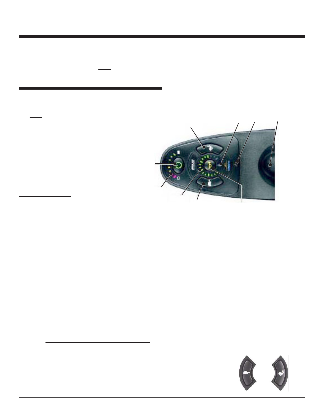
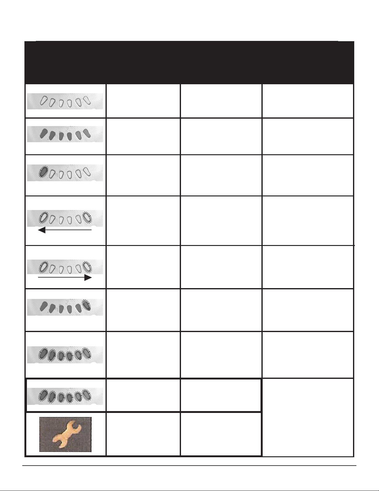
3. BATTERY INDICATOR.
Recharge before undertaking a long trip.
as possible.
4. THROTTLE CONTROL JOYSTICK LEVER. The joystick mounted on the top of the
control panel is both the throttle and direction control lever (Push Slowly). Pushing the joystick
with your thumb in the direction of the horn button on the control faceplate will make the bed
go forward or backward accordingly. Pushing the joystick in slightly will makes the bed begin to
move. The further you depress the joystick, the faster the bed will moves. The top speed set by
joystick will stop power to the motor, activate the brakes, and you will come to a complete stop.
For faster stops in forward, pull the joystick into reverse until the unit stops moving, then release
the joystick.
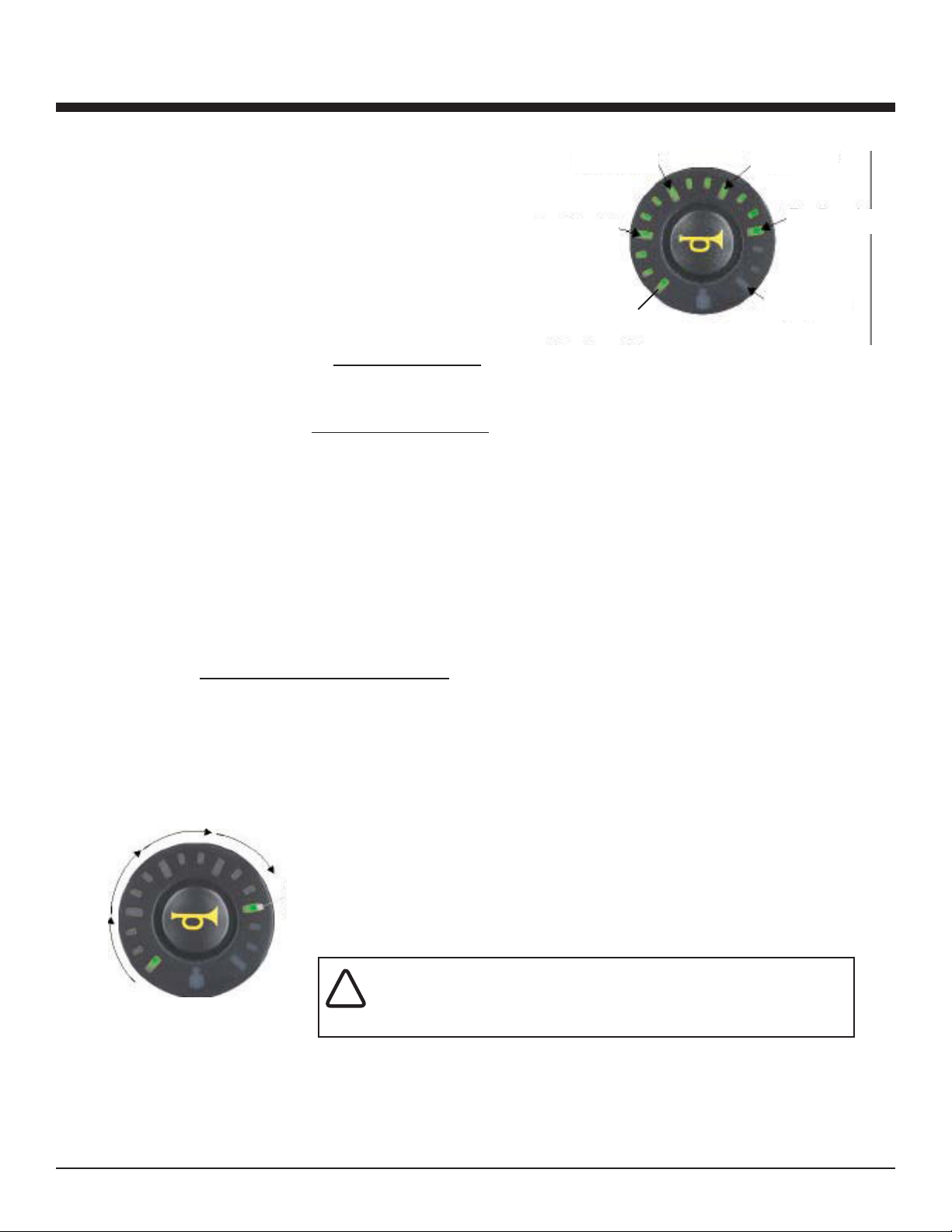
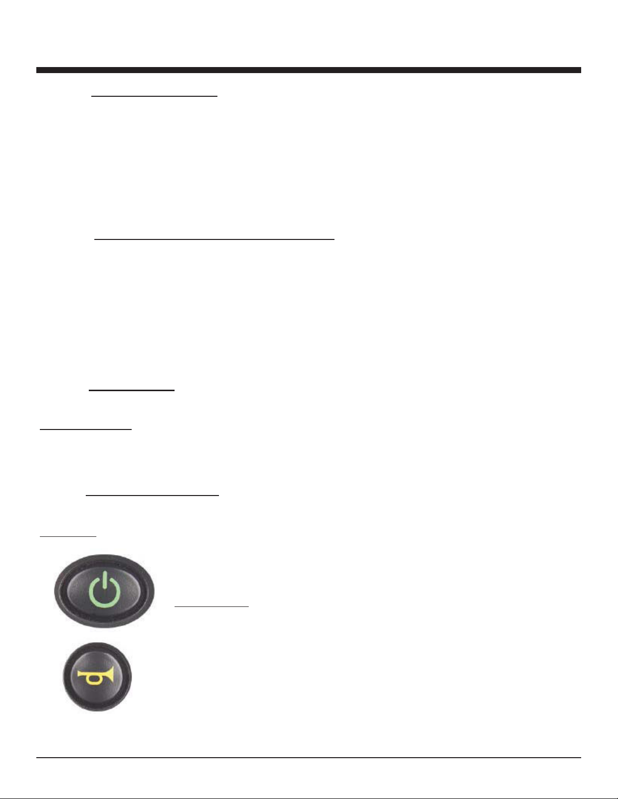
5. HORN BUTTON
The joystick also comes equipped with a built in horn, activated by depressing the horn button.
Should the joystick / brake control system not stop the unit, turning the power
off will engage all brakes and stop the unit abruptly. This backup system should only be used in
6. LOCKING THE SHARK
powerchair will then turn off.
(approximately 10 seconds). The current state-of-charge will then be dis-
drive again normally.