Burton AIM-50 User manual

A
IM-50
™
INSTALLATION MANUAL
WALL MOUNT VERSION
The Right Ligh
t
EXAMINATION
PERFORMANCE RELIABILITY VALUE


Installation Manual
AIM-50™Wall Mount
The following models are covered in this manual:
A50W AIM-50™ Wall mount version 120 V
A51W AIM-50™ Wall mount version 100 V
A52W AIM-50™ Wall mount version 240 V
A53W AIM-50™ Wall mount version 230 V
This product was designed and assembled in the U.S.A. by
BURTON MEDICAL PRODUCTS CORP.
21100 Lassen St.
Chatsworth, CA 91311
U.S.A.
Questions?
Tel. (800) 444-9909
(818) 701-8700
Fax (800) 765-1770
(818) 701-8725
www.burtonmedical.com
This manual to
remain with end user.

2 AIM-50™ Installation Manual −Wall Mount Version 5000145 A01
Table of Contents
Table of Contents..........................................................................................................................................2
Introduction ....................................................................................................................................................3
Symbols Used in This Manual .................................................................................................................4
Transportation and Storage ....................................................................................................................4
Safety Precautions .....................................................................................................................................4
Assembly Preparations.............................................................................................................................5
Support and Anchorage ...........................................................................................................................5
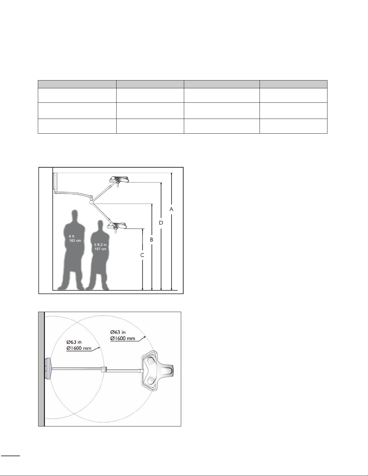
Mounting Height ........................................................................................................................................6
Range of Motion ........................................................................................................................................6
Unpacking and Inspection........................................................................................................................7
Installation........................................................................................................................................................8
Wall Support Structure............................................................................................................................8
Wiring ..........................................................................................................................................................8
Installing the Wall Mount.........................................................................................................................8
Connecting Power ....................................................................................................................................9
Installing the Wall Switch...................................................................................................................... 10
Installing the Extender Arm With Spring Arm ................................................................................ 11
Mounting the Light Head ...................................................................................................................... 12
Final Testing............................................................................................................................................. 14
Adjusting Arm Tension ......................................................................................................................... 14
Static Inspection...................................................................................................................................... 14
Declaration of Acceptance................................................................................................................... 14
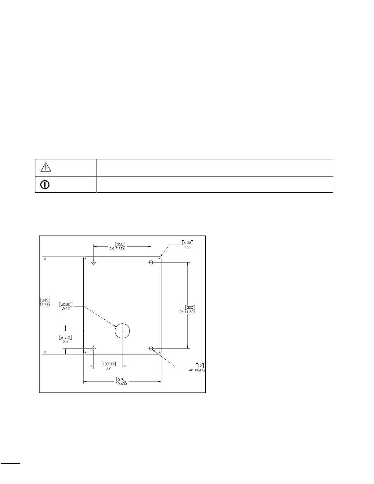
Equipment Anchorage Diagrams......................................................................................................... 15
This manual contains detailed information on the above, but responsibility for effective installation
ultimately rests with skilled and qualified contractors. Products should at all times be handled by
qualified staff; it is the responsibility of the user to ensure this is the case.

AIM-50™ Installation Manual −Wall Mount Version 5000145 A01 3
Introduction
Dear Installer,
Congratulations on your purchase of the AIM-50™ Examination Light!
The installation manual gives instructions on how to install the AIM-50™ Examination Light Wall
Mount Version. For instructions on operation, maintenance and further description of the product
please refer to the Operation & Maintenance manual.
Please read these installation instructions very carefully and follow the safety instructions and
requirements.
This product was designed and manufactured in the U.S.A. by:
Burton Medical Products
21100 Lassen Street
Chatsworth, CA 91311
U.S.A.
Questions?
Tel: (800) 444-9909
(818) 701-8700
Fax: (800) 765-1770
(818) 701-8725
www.burtonmedical.com
Copyright © 2008 Burton Medical Products

4 AIM-50™ Installation Manual −Wall Mount Version 5000145 A01
Symbols Used in This Manual
WARNING Disregarding this instruction can present the risk of a serious or fatal injury.
CAUTION Disregarding this instruction can result in medium to light injury and damage to
property.
IMPORTANT Provides usage tips and useful information.
Transportation and Storage
The following storage conditions apply:
•Temperature: 0 - 70 ºC (32-158ºF)
•Relative humidity: 10 - 75 % (no condensation)
•Air pressure: 500 - 1060 hPa
Store only in closed or covered spaces; thereafter, the values of the operating conditions in the
usage instructions apply.
Safety Precautions
WARNING Failure to properly follow installation and preventive maintenance instructions
may result in mechanical failure.
WARNING Before undertaking any work, ensure that the branch circuit power is off and
secured from accidentally being switched on again.
NOTE This light should only be installed by qualified electrical and structural
contractors*.
NOTE
It is the responsibility of the customer to make sure the supporting wall /
ceiling and the anchoring is safe, adequately strong and in compliance with all
applicable building codes. (See: Static inspection on page 14 and the section
Support and Anchorage below.)
*Approved wiring shall be routed inside conduit between the wall switch junction box and the steel support plate (to
the wall mount). The installation shall meet requirements contained in the latest issues of the NEC and NFPA, and
other local and national building codes; as they apply to hospitals, clinics, medical offices, and the like.

AIM-50™ Installation Manual −Wall Mount Version 5000145 A01 5
Assembly Preparations
Tools and Accessories Required:
•Drill
•Level
•9/16” (14,3 mm) open-end wrench (or adjustable wrench)
•Wire cutter/stripper
•Allen key (3/32 in / 2,4 mm)
•Screwdriver, small flat-blade
•Screwdriver, small Phillips
•Wire nuts and wiring for supply connections
Materials Required:(not supplied with light)
•Mounting plate. (See page 8)
•Washers and spacers. (For mounting flush with wall)
•Special anchors for concrete or brick walls.
•Switch box – For wall switch panel.
•Electrical wire—To light.
•Conduit for electrical lines to wall mount / switch.
•Wall switch. (For 100 and 240 V versions only)
Support and Anchorage
To prevent sway and provide proper support of the light, the wall mount must be attached to a
structurally-sound wall or similar structure.
Most walls will require adequate reinforcing to hold the light. The installing contractor is
responsible for providing this reinforcement to suit the individual requirements for each
installation.
A typical reinforcement consists of a ¼” (6 mm) steel plate. Make certain the mounting plate is
vertical, or the arm may “drift”.
Equipment anchorage diagrams are supplied with these instructions to help with the installation
(see page 14). The diagrams were prepared by a California-licensed Structural Engineer. If the
lights are installed accordingly, the system will meet requirements of the State Seismic Codes.

6 AIM-50™ Installation Manual −Wall Mount Version 5000145 A01
Mounting Height
The proper height of the light should be set by the end user. This depends on the height of the
examination tables, types of procedures and the user’s preferences. (See Figure 1 below)
The following table shows the range of the light with the different mounting heights.
Mounting height A Pivot point B Lower limit C Higher limit D
8.0 ft (2440 mm) 67 in (1702 mm) 43 in (1092 mm) 84 in (2134 mm)
9.0 ft (2745 mm) 79 in (2007 mm) 55 in (1397 mm) 96 in (2438 mm)
10.0 ft (3050 mm) 91 in (2311 mm) 67 in (1702 mm) 108 in (2743 mm)
Range of Motion
Figure 1: Vertical range of motion
Figure 2: Horizontal range of motion

AIM-50™ Installation Manual −Wall Mount Version 5000145 A01 7
Unpacking and Inspection
Carefully unpack the cartons and match the parts received with the parts list enclosed.
Before Reporting Shortages:
1. Be sure you have received the correct number of boxes, cartons, etc., as shown on the bill of
lading.
2. Check the entire shipment against the enclosed packing slip.
3. Items indicated in the column headed “Back Order” are not included in the shipment and will
follow later.
4. Be sure that nothing has been removed from the cartons before they are checked by the
individual in charge.
5. Empty all boxes completely, open all inside containers, and examine all packing material to
ensure small articles are not overlooked.
If a Shortage or Damage Occurs:
1. You, the receiver, not Burton, are responsible for filing any claim(s) with the delivering carrier
within five (5) days after receipt of the shipment.
2. If damage or shortage occurs in transit, the delivering carrier is required by law to make
notation of a shortage or damage. This notation is to be made on the bill of lading.
3. If, in your opinion, there may be concealed damage, an agent from the delivering carrier is
obligated to make an inspection after the goods are unpacked.
4. Do not destroy packing material until after the agent has made out his report.
5. All claims must be made to the carrier, not Burton.
6. Written authorization must be obtained from Burton before merchandise can be returned.

8 AIM-50™ Installation Manual −Wall Mount Version 5000145 A01
Installation
Wall Support Structure
The engineer of record for the building shall provide a support structure designed to support
weights and forces shown on the Equipment Anchorage Diagrams on page 15. When the support
structure is in place the static inspection sheet on page 14 should be filled out.
Wiring
Switch wiring (contractor-supplied) must be three-conductor minimum AWG 18 from the switch
to the terminal block. Wiring and conduit must meet NEC, local, and national fire protection
codes.
Installing the Wall Mount
CAUTION Before cutting in the wall, check with building maintenance so that you do not cut
through existing electrical, plumbing or gas lines.
NOTE It is the responsibility of the contractor and engineer of record to design and build a
suitable structure for mounting the light.
1. The following figure shows an example of a mounting plate which can be used to mount the
wall mount to a wall. The attachment method (screws), number of screws, and location of the
screws will vary depending on the type and structure of the wall, therefore it is not shown.
Figure 3: Contractor supplied mounting plate (dimensions are inches [mm])
2. Assemble the mounting plate to the bearing structure of the wall.
3. Feed the wires coming through the central hole in the mounting plate into the wall mount
assembly.

AIM-50™ Installation Manual −Wall Mount Version 5000145 A01 9
4. Mount the wall mount to the mounting plate. Use four (4) 3/8” (10 mm) bolts, plain washers,
split lock washers, and nuts.
5. Tighten all fasteners and check that the wall mount is secure.
Connecting Power
NOTE Wire and cabling to be routed and connected by certified electrical contractor.
NOTE Only installation connections are shown. For a complete wiring diagram, please refer
to the Operation & Maintenance manual.
1. Route conduit and electrical lines to wall mount. Use AWG 16 (1,5mm2).
2. Wire the wall mount as shown in the illustration above (120V version is illustrated).

10 AIM-50™ Installation Manual −Wall Mount Version 5000145 A01
Notes:
•Connect the 0 V neutral wire (normally white) to the terminal block marked “N”.
•Connect the 120V power wire (normally black) to the terminal block marked “L1”. This
voltage could be 100V or 240V depending on the type of wall model purchased.
•Connect protective earth to the terminal block marked with the symbol .
•Secure cable with strain relief.
3. Install the cover on the wall mount and secure it by tightening the 4 screws on the sides.
Installing the Wall Switch
115V / 120 V versions: Install wall switch furnished with the product to a standard junction box
per local codes. The wires that go to the light fixture are labeled “to light fixture”.
100V / 230V / 240V versions: Install wall switch per local codes. Wall switch is not furnished
with the product.

AIM-50™ Installation Manual −Wall Mount Version 5000145 A01 11
Installing the Extender Arm With Spring Arm
WARNING
Danger of injury
If the washer is not installed, the retaining ring can get loosened.
The equipment can then fall from its fixtures and cause serious
injuries. Always install the washer.
WARNING -
Electrical shock
The support system can become live if the power cables are
damaged at the plug. The voltage can pose a danger to life. Install
the plug carefully.
1. Unscrew the cross-slotted screw (a).
2. Remove the plug cap (b).
3. Lift the arm onto the shaft of wall mount (d).
4. Insert the washer (c) on the shaft and install the retaining ring (e).
5. Check whether the extender arm with spring arm is seated firmly.
6. Insert the safety screw (f) through the hole and thread into the shaft on the wall mount (d) using
the included 2.5mm hex key.
7. Make sure the screw is fully seated against the shaft on the wall mount (d). The arm should
rotate smoothly.
8. Insert the plug cap (b) into the shaft until it locks into position.
9. Fasten the cross-slotted screw (a) to secure the plug cap.

12 AIM-50™ Installation Manual −Wall Mount Version 5000145 A01
Mounting the Light Head
WARNING
Danger of injury
The spring arm, when pressed downwards, can spring upwards and result in
injuries. During the installation of the light head, no one should be present
within swiveling range of the spring arm.
CAUTION
Danger of injury Key must be properly installed to avoid safety hazard.
Figure 1 Figure 2
1. Figure 1 above shows the correct orientation of the spring arm to the light head.
2. Loosen the brake screw (b) and remove the protective cover (d) only.
3. Rotate the collar (c) 180º so that the slot in the collar aligns with the slot in the spring arm (a)
illustrated in the lower right of figure 2.
4. Unite the electrical connectors.
Figure 3 Figure 4
5. Make sure the plastic bearing (i) is on the yoke and there is grease in the groove (h). The
connectors are not shown in figure 3.

AIM-50™ Installation Manual −Wall Mount Version 5000145 A01 13
6. After the connectors are mated, push the yoke into the spring arm.
7. Put the key (e) completely into the slot (a), so that the key is engaged into the yoke groove (h).
See figure 4.
Figure 5
8. Rotate the collar (c) 180 degrees as shown in figure 5.
9. Before installing the brake screw (b), check the attachment of the light head by pulling
and rotating it at the same time. The light head should rotate smoothly and not pull out of the
arm.
Figure 6
10. Thread the brake screw (b) into the collar as shown in figure 6 and tighten it until the rotating
joint has the desired friction.

14 AIM-50™ Installation Manual −Wall Mount Version 5000145 A01
Final Testing
Energize the light assembly by turning the wall switch on to check proper operation.
The arm system should swing easily within the range of motion as illustrated on page 6.
Adjusting Arm Tension
The spring inside the arm is pre-adjusted from the factory. If, however, the light-head drifts up or
down, please refer to the Operation & Maintenance manual for guidance on how to adjust this.
Static Inspection
NOTE: The static (structural) inspection must be carried out before the installation of the wall
or ceiling fastening.
•The strength of the construction must be designed, checked and certified by a
structural engineer.
•The respective regional construction regulations that apply must be followed.
•If an erroneous hole is drilled by mistake (e.g. drilling of a reinforcement rod) the structural
engineer who is responsible must be contacted, since adequate static load distribution in the
ceiling may have been jeopardized.
Declaration of acceptance:
It is hereby certified that the supporting wall/ceiling and the anchoring of the AIM-50™
suspension system is safe and adequately strong.
Project: __________________________________
__________________________________
__________________________________
Anchoring (please check the one that is applicable):
- with counter-plate O
- other O
Location: __________________________________
__________________________________
Signature/Stamp (Structural Engineer / Construction Authority)

AIM-50™ Installation Manual −Wall Mount Version 5000145 A01 15
Equipment Anchorage Diagrams
Wall mount Version - overview

16 AIM-50™ Installation Manual −Wall Mount Version 5000145 A01
Wall mount Version – plan at wall


BURTON MEDICAL
21100 Lassen Street
Chatsworth, CA 91311 USA
Phone: 800-444-9909, 818-701-8700
Fax: 800-765-1770, 818-701-8725
www.burtonmedical.com
The Ri
g
ht Li
g
h
t
Other manuals for AIM-50
1
Table of contents
Other Burton Medical Equipment manuals
Popular Medical Equipment manuals by other brands

Orliman
Orliman 2010-S INSTRUCTIONS FOR USE AND PRESERVATION

Braun
Braun Aesculap Quintex Instructions for use/Technical description

OCULUS
OCULUS Easygraph 70620 instruction manual

Otto Bock
Otto Bock 3F1-1 Instructions for use

Canon
Canon CXDI-1 Operation manual

Arthrex
Arthrex AR-1627-20 Instructions for use

Beurer
Beurer NA 20 Instructions for use

Exsurco Medical
Exsurco Medical amalgatome MD Quick reference guide

Cardioline
Cardioline ECG100L user manual

Hologic
Hologic ThinPrep 5000 Quick reference guide

Nonin
Nonin NoninConnect Elite 3240 user manual

Ultrasound Technologies
Ultrasound Technologies PFM1 operating manual