Burton AIMLED070 Series User manual

AIM HI LED
Floor Stand, Wall & Ceiling Versions
Installation Instructions
5000705 A01 Installation Instructions

2
Introduction
Congratulations on your purchase of the AIM HI LED series light!
The AIM HI LED is designed to give the professional health care market superior
performance, reliability and value. The lights contain advanced optical and mechanical
solutions intended to offer you an optimal working environment for efficient and comfortable
procedures. Built in features of the AIM’s include intensity control, color correction, shadow
reduction, light distribution, spot appearance, maneuverability and focus. The AIM´s solid
and durable construction ensures trouble-free professional lighting and is supported by a
five (5) year service life and warranty.
Intended Use:
The AIM HI LED exam light is an easy to use medical lighting fixture that can be utilized in
a variety of spaces, including hospitals, doctor offices, and other healthcare environments
requiring examination lighting. This fixture shall not be used in healthcare environments
that are adjacent to residential dwellings. This fixture is also excluded for use in areas near
active HF SURGICAL EQUIPMENT and the RF shielded room of an ME SYSTEM for
magnetic resonance imaging, where the intensity of EM DISTURBANCES is high. This
product is not intended for use in operating and emergency rooms.
A removable and autoclavable handle (which also serves as bulb-focus control) accepts
pre-sterilized covers.
This manual contains guidance on how to install the AIM HI LED light(s).
Burton Medical is a leading manufacturer of medical lighting. The product lines encompass
lights for procedure and examinations. You are welcome to find out more on our web site at
www.burtonmedical.com.
Unpacking and Inspection
Carefully unpack the cartons and match the parts received with the parts list enclosed.
Before Reporting Shortages:
Be sure you have received the correct number of boxes, cartons, etc., as shown on the bill of
lading.
Check the entire shipment against the enclosed packing slip.
Items indicated in the column headed “Back Order” are not included in the shipment and will
follow later.
Be sure that nothing has been removed from the cartons before they are checked by the
individual in charge.
Empty all boxes completely, open all inside containers, and examine all packing material to
ensure small articles are not overlooked.
If a Shortage or Damage Occurs:
1. You, the receiver, not Burton Medical, is responsible for filing any claims with the
delivering carrier within five (5) days after receipt of the shipment.
2. If damage or shortage occurs in transit, the delivering carrier is required by law to make
notation of a shortage or damage. This notation is to be made on the bill of lading.
3. If, in your opinion, there may be concealed damage, an agent from the delivering
carrier is obligated to make an inspection after the goods are unpacked.
4. Do not destroy packing material until after the agent has made out his report.
5. All claims must be made to the carrier, not Burton Medical.
6. Written authorization must be obtained from Burton Medical before merchandise can be
returned.

3
Table of Contents
1.0 Tools List .............................................................................................. 4
2.0 Parts List............................................................................................... 4
2.1 Floor Model ..................................................................................... 4
2.2 Wall Model ...................................................................................... 5
2.3 Single Ceiling Model........................................................................ 5
2.4 Double Ceiling Model ...................................................................... 5
3.0 Safety Instructions................................................................................. 6
3.1 Symbols .......................................................................................... 6
3.2 Safety Precautions........................................................................... . 6
4.0 Floor Stand Model ................................................................................ 7
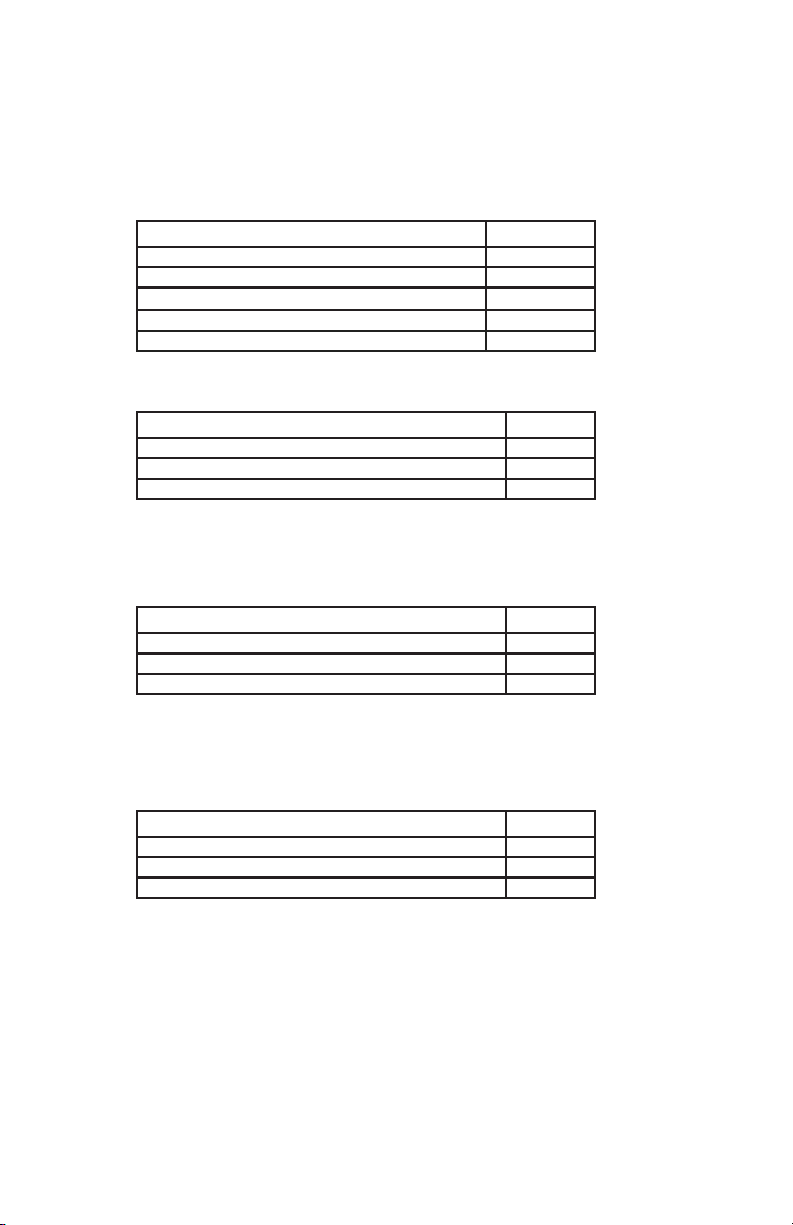
4.1 Base Post Assembly................................................................... ..... 7
4.2 Handle Assembly.............................................................................12
4.3 Spring Arm Assembly..................................................................... 14
4.3.1 Elbow Cover Removal Instructions ........................................ 15
5.0 Wall Mount Model ............................................................................... 17
5.1 Mounting Height ........................................................................... 17
5.2 Ranges of Motion ....................................................................... ..17
5.3 Installation (Wall Support and Anchorage)..................................... 18
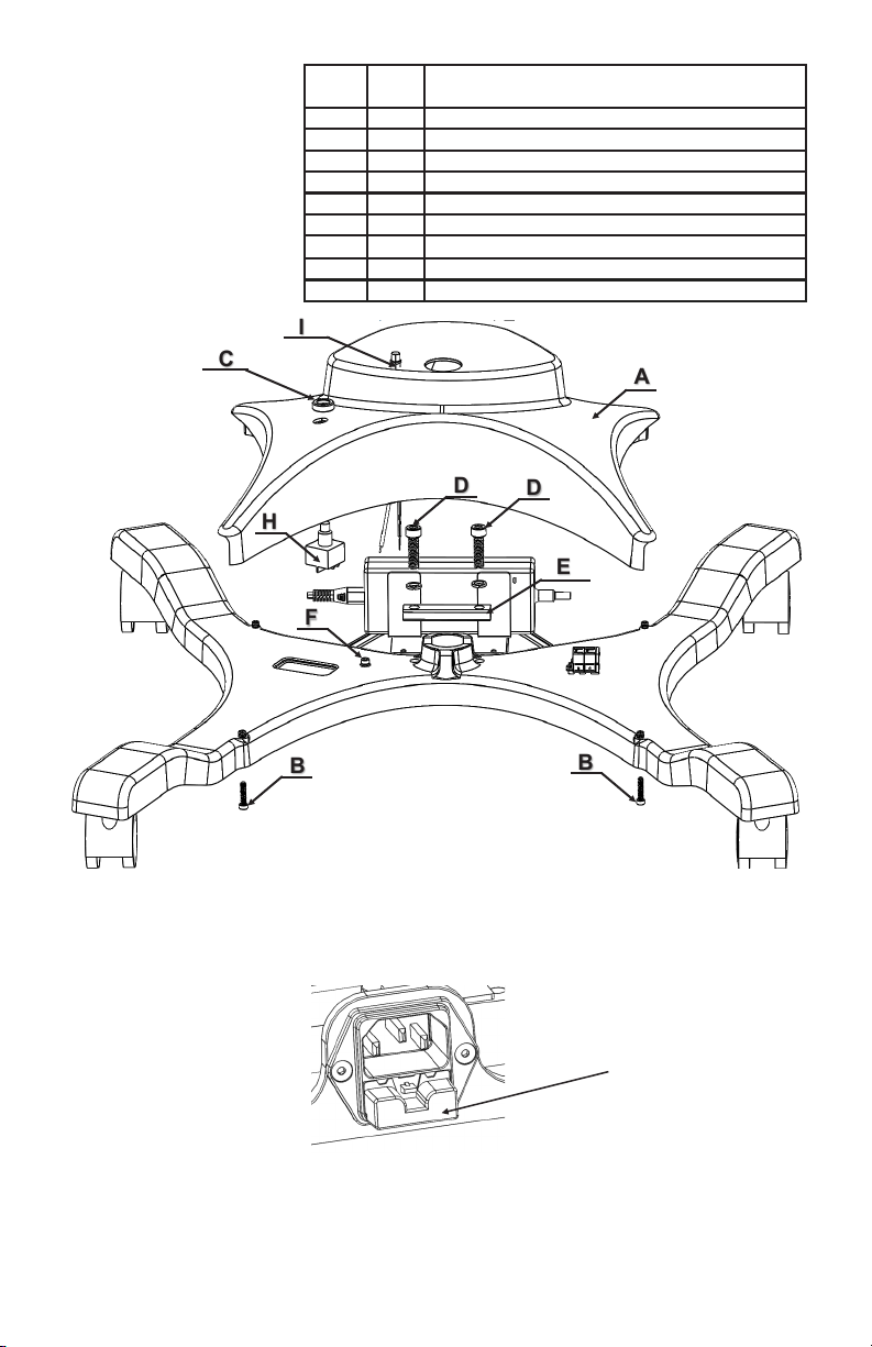
5.4 Connecting Power.......................................................................... 20
5.4.1 Wall Switch Wiring................................................................. 20
5.4.2 Wall Mount Wiring ................................................................. 21
6.0 Ceiling Mount Models............................................................................ 22
6.1 Mounting Height........................................................................... ... 22
6.2 Support and Anchorage................................................................. 22
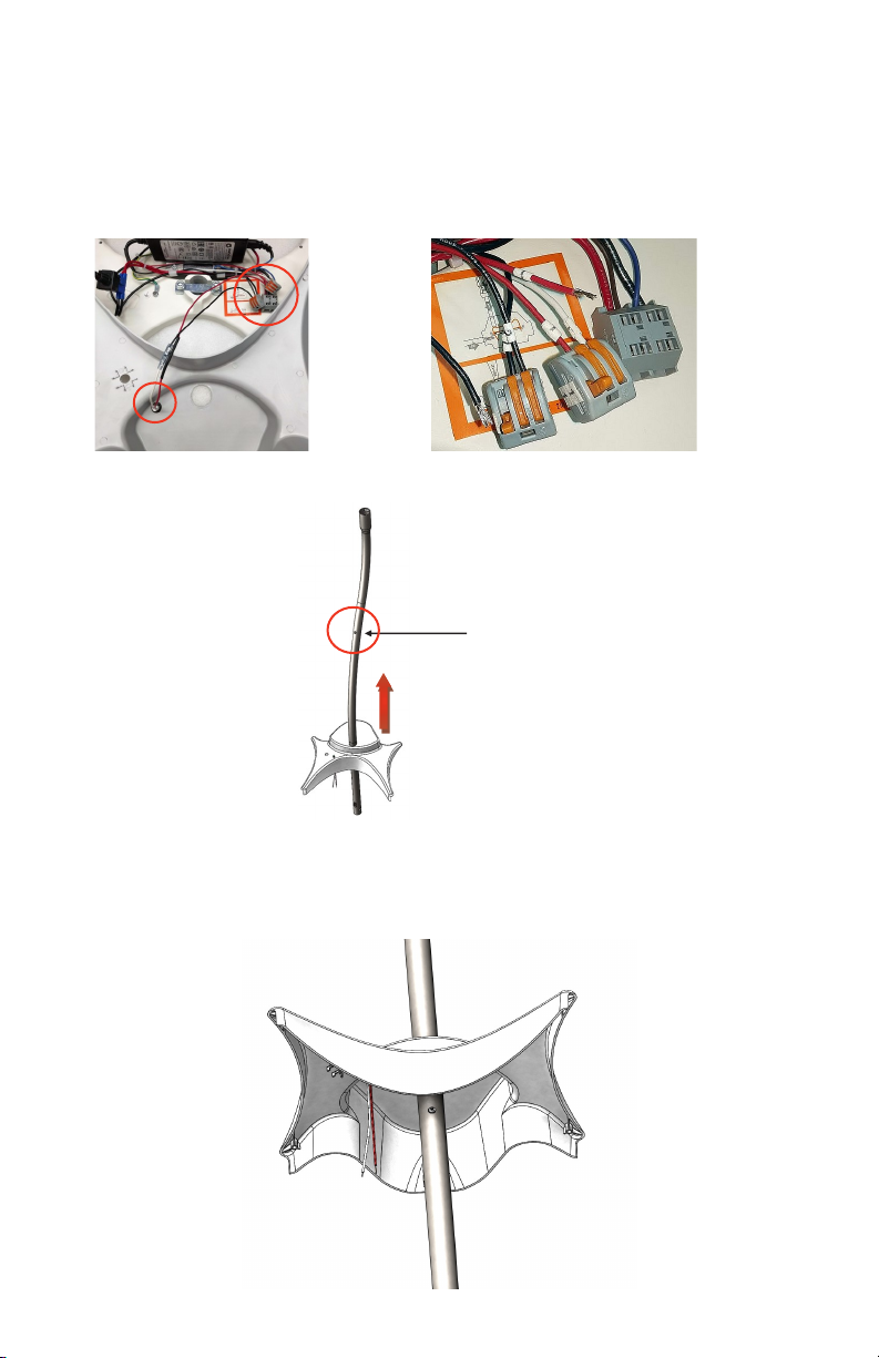
6.3 Cutting the Down Tube................................................................. .. 23
6.4 Ranges of Motion.............................................................................23
6.5 Ceiling Installation (AIM HI LED Single or Double Ceiling Model)......24
6.6 Installing the Junction Box............................................................. 25
6.7 Installing the Ceiling Casting............................................................25
6.8 Installing the Down Tube..................................................................25
6.9 Connecting Power ......................................................................... 27
6.9.1 Wall Switch Wiring.................................................................. 28
6.9.2 Ceiling Mount Wiring .............................................................. 29
6.10 Ceiling Bell Housing Assembly .................................................... 30
7.0 Extension/Spring Arm - Wall and Ceiling Assembly.................................30
8.0 Mounting the Light Head to the Spring Arm........................................ ... 34
9.0 Cleaning ............................................................................................... 35
9.1 Normal Cleaning............................................................................. 35
9.2 Extensive Cleaning......................................................................... 35
10.0 Equipment Anchorage Diagrams ........................................................ 36
11.0 AIM HI LED Single/Double/Wall Mount Wiring Diagram......................... 40
12.0 Warranty Information........................................................................... 41
13.0 Equipment Maintenance Log............................................................... 42
Burton Medical Information ......................................................................... 44

4
1.0 Tools List
There will be various tools needed throughout the assembly of the Burton Medical
floor, wall & ceiling versions. The tools needed are as follows:
• 2.5mm Allen Key (floor model only, supplied)
• 3mm Allen Key (floor model only, supplied)
• 4mm Allen key (supplied)
• 5mm Allen key (supplied)
• 6mm Allen Key (floor model only, supplied)
• 3/16 Allen key (ceiling mount only, supplied)
• 3/32 Allen key (ceiling mount only, supplied)
• Needle Nose Pliers
• # 2 Phillips Screwdriver
• Medium strength thread locker (Loctite or similar)
NOTE: Retain ALL Allen keys for future maintenance.
The following models are
covered in this manual: 100VAC- 240VAC 50/60Hz
AIMLED070 series
ALED070SC LT, SC, ALED070, BURTON
ALED070DC LT, DBL CEIL, ALED070, 100-240V, BURTON
ALED070W LT, WALL MNT, ALED070, BURTON
ALED070FL00 LIGHT, FL, ALED070, NEMA 5-15P
ALED070FL01 LIGHT, FL, ALED070, CEE 7/7
ALED070FL02 LIGHT, FL, ALED070, AS/NZS 3112
ALED070FL03 LIGHT, FL, ALED070, BS1363
AIMLED100 series
ALED100SC LT, SC, ALED100, BURTON
ALED100DC LT, DBL CEIL, ALED100, 100-240V, BURTON
ALED100W LT, WALL MNT, ALED100, BURTON
ALED100FL00 LIGHT, FL, ALED100, NEMA 5-15P
ALED100FL01 LIGHT, FL, ALED100, CEE 7/7
ALED100FL02 LIGHT, FL, ALED100, AS/NZS 3112
ALED100FL03 LIGHT, FL, ALED100, BS1363

5
3.0 Safety Instructions
NOTE: assembly of this product must be carried out by a trained service technician. At
some points of assembly you may require the assistance of an additional person.
• Read these assembly instructions carefully before assembling the AIM HI LED light.
It will protect you and others from potential injuries that may occur.
• Make sure to follow these instructions when assembling. DO NOT modify or omit
any parts on the Burton Medical AIM HI LED light before, during, or after assembly.
• If problems are encountered when assembling, contact Burton Medical technical
support. The contact information can be found at the end of this manual.
• To avoid an electric shock, make sure the AIM HI LED light is not connected to a
main power when assembling.
• These assembly instructions only apply to the products listed here and should not
be used for any other products.
3.1 Symbols
In these assembly instructions and on the device, important points have been marked
with symbols. The symbols have the following meanings:
ELECTRIC SHOCK
Electric shock warning symbol. Non-compliance with this symbol may result in
injuries due to electric shock.
3.2 Safety Precautions
CAUTION
Failure to properly follow installation and preventive maintenance instructions may
result in mechanical and/or electrical failure.
WARNING
Before undertaking any work, ensure that the main power is off and secured from
accidentally being switched on again.
NOTE
This light should only be installed by a trained service technician.
NOTE
It is the responsibility of the customer to make sure the supporting wall / ceiling and
the anchoring is safe, adequately strong, and in compliance with all applicable
building codes. (See Equipment Anchorage Diagrams.)
CAUTION
Non-compliance with caution notes may cause injuries or material damage.
WARNING
Disregarding this instruction can present the risk of serious or fatal injury.
NOTE
Provides usage tips and useful information.

6
2.2 Wall Model
Part Quantity
Extension/Spring Arm (with mounting hardware) 1
Wall Mount with cover 1
Light Head 1
2.3 Single Ceiling Model
2.4 Double Ceiling Model
If you are missing any items please contact customer service. See back of manual for contact
information.
Part Quantity
Extension/Spring Arm (with mounting hardware) 1
Ceiling Mount with cover 1
Light Head 1
Part Quantity
Extension/Spring Arm (with mounting hardware) 2
Ceiling Mount with cover 1
Light Head 2
2.0 Parts List
The Burton Medical lights come in multiple boxes and contain several pieces of hard
ware, and manuals. Ensure your boxes contain all items as listed below:
2.1 Floor Model
Part Quantity
Floor Base 1
Upright Post 1
Handle with hardware and casters 1
Spring Arm 1
Light Head 1

7
A
C
D
E
D
F
H
BB
I
Figure 1.
Part
#
Qty Description
A1Base Cover
B4Base Cover Screws
C1Electrical Switch Nut
D2M8 Attachment Bar Screw and Lock Washer
E1Post Attachment Bar
F1Ground Screw and Washers
G1Post/Upright (not shown below)
H1Push Button Switch
I1Green Indicator Light
4.0 Floor Stand Model
4.1 Base Post Assembly
Parts (Refer to Figure 1)
Assembly Instructions:
1. Using your finger release the fuse holder on the power outlet by pushing downward on
the tab and pulling outward. Place the fuse holder aside. See Figure 2.
2. Using a 3mm Allen Key, remove four (4) x M4 screws (B) from underside of base to
release the plastic cover. Place screws aside for reassembly. Refer to Figure 1.
Fuse Holder
Figure 2.

8
3. Remove the electrical switch nut (C) by unthreading it from the push button switch (H).
Place it aside. Refer to Figure 1.
4. Carefully pull the bottom of the plastic cover over the power outlet. Lift the base cover up
around 6” (A). Then disconnect red and black wires form green indicator light (I) attached
to internal connectors, refer to Figure 3A. To release wire lift corresponding orange tab
from each connector, refer to Figure 3B.
5. Take the non-flared end of the post base and slide it through the post opening of the
base cover. This can be seen in Figure 4.
6. Using the 2.5mm Allen key, remove the M3 screw on the post. It is located approximately
half way up the post. Refer to Figure 4, 5.
7. Slide the cover towards the flared end of the post as far as possible. Then re-install the
M3 screw into the post. This is to hold the cover up while other work is done. Refer to
Figure 5.
Figure 3A. Figure 3B.
Figure 4
M3 screw location
Figure 5: M3 post screw.

9
Figure 7: Top of the post.
10. On the base, remove two (2) M8 screws, washers (D), and attachment bar (E) using
the 6mm Allen key. Place hardware aside for reassembly. Refer to Figure 8.
8. Using needle nose pliers, pull the connector and approximately one inch of cable through
the oval hole at the bottom of the post. Refer to Figure 6.
9. Pull the cable through the opening at the top of the post, until connector is visible. Refer
to Figure 7.
Figure 6: Bottom of the post.
Figure 8: M8 screws and attachment bar.
D
E
D

10
Figure 9B: Post attachment bar.
13. Secure the attachment bar using the two (2) M8 washers and two (2) M8 screws.
Tighten the screws using the 6mm Allen key.
14. Ensure that the attachment bar has fully clamped the post and there is no movement of
the post.
15. Remove the ground screw and washers (F) using the 3mm Allen key.
Refer to Figure 10.
Figure 10:
Ground screw.
11. Position the post so that the arch is located at the back of the base, refer to Figure 9A.
Insert the post into the hole in the base. Slide the attachment bar through the square
slots in the post. When inserting the post, make sure the wires (A) are facing the front
of the base and NOT towards the power supply.
12. Align the holes of the attachment bar with the holes on the base (B). Refer to Figure
9B.
WARNING: When performing Step 12 to 14, make sure the attachment
bar is in proper position in the post, and that it is secure to the base.
Failure to do so may cause injury.
Figure 9A: Post orientation.
FRONT
POST
ARCH
POWER
SUPPLY A
FRONT
BB
F

11
17. Connect the receptacle coming out from the bottom of the post to the power supply
Harness. CAUTION: make sure the connectors are fully engaged. See Figure 11B.
18. Remove the M3 screw holding up the base cover and allow the cover to slide down
to the base of the floor stand. Replace and secure M3 screw into the post.
19. Reconnect wires from Green Indicator switch (I) to its corresponding connectors.
Connect RED wire labeled “1” to three port connector labeled “1”. Then connect BLACK
wire labeled “2” to three port connector labeled “2”, refer to Figure 12A. Re-install the
pushbutton switch into the underside of the base cover and secure it using the electrical
switch nut. Ensure proper orientation of the bottom of the switch into the tabs as shown
in Figure 12B.
16. Align the green and yellow ground ring terminal coming out of the post with the green
and yellow ground ring already connected to the base. Align them both with the same
hole on the base as before, and re-fasten in the same location. See Figure 11A.
Figure 11A: Ground connections.
Figure 12B: Proper orientation of
foot switch.
20. Re-install base cover to the base, by inserting the four (4) M4 screws from below.
Ensure the cover is not pinching any wires. Tighten screws using the 3mm Allen key.
Do not overtighten!
21. Reinstall fuse holder removed in step 1, ensuring fuse holder clicks into place and is
secure.
ELECTRIC SHOCK: Make sure the electrical connection is made properly by
following steps below. Failure to do so may cause electric shock. If you have
any problems or questions with these steps contact Burton Medical.
Figure 11B: Power supply connections.
Figure 12A: Green Indicator light
connections.
12

12
4.2 Handle Assembly
Figure 13: Post and handle assembly.
Part # Qty Description
G1Post / Upright
J1Handle
Assembly Instructions:
1. Remove the screws in the handle using a Phillips screwdriver to separate it into two
pieces.
2. On the smaller portion of the handle there is larger center hole. This hole is used for
positioning the handle to the post. Ensure the head of the positioning screw (which is
located half way up the post) is inserted into this hole. Refer to Figure 14A & B.
Figure: 14A
J
G
Figure: 14B

13
3. With small piece positioned over the posts setscrew, feed two Phillips screws on each
side, refer to Figure 15A. Then attach large handle to the post on the opposite side,
refer to Figure 15B. Using Phillips screwdriver engage 3-4 threads of the first screw
then repeat the process on the opposite screw. Secure the handle to the post by hand
tightening both screws.
WARNING: Alternate tightening each screw to prevent handle from binding.
WARNING: Do not overtighten, leave small gap of equal size between small piece and
large piece of the handle, refer to figure 16B.
4. Properly installed handle, refer to Figure16A & B.
Figure: 15A Figure: 15B
Small piece
Figure: 16A
Large piece
Figure: 16B
gap gap

14
4.3 Spring Arm Assembly
Assembly Instructions:
1. Remove the spring arm elbow covers (L). Refer to Figure 18.
Part # Qty Description
G1Post/Upright Assembly
K1Spring Arm Assembly
L1 Elbow Cover
Figure 17: Spring arm assembly.
G
K
L

15
Step 1: Covers
Installed. Step 2: Insert slot driver
into the parting line as
shown.
Step 3: Turn driver 90° to
separate the covers.
Step 4: Pry the LH cover
up.
Step 5: Pry the LH cover
forward.
Step 6: Pry the RH cover
up.
Step 7: Pry the RH cover
forward.
4.3.1 Elbow Cover (L) Removal Instructions:
Figure 18: Elbow cover removal instructions.

16
2. With covers removed, use a 3mm Allen key to remove the rotational stop screw (B)
and lock washer (C) from the back of spring arm post. Take care to ensure the lock
washer (C) and shim washer (A) do not fall off during this step. See Figure 19.
3. Connect the spring arm electrical connector to the mounting post electrical connector
by pushing them together.
4. Slide the spring arm into the mounting post. Ensure the washer (A) is present and did
not fall off the spring arm shaft.
5. Using 3mm Allen key, fasten the rotational stop screw with lock washer into the back
of the spring arm post. Refer to Figure 20.
Figure 19: Remove stop screw.Figure 20: Install stop screw.
WARNING: Always make sure the rotational stop screw is properly fastened
to avoid a safety hazard.
6. Gently snap right hand cover onto spring arm in reverse order of removal instructions
described above. When performing this step, ensure that the sliding cover (already on
the spring arm) mates with a groove on the inside of the spring arm cover. Refer to
Figure 21.
7. Gently snap left hand cover onto spring arm in reverse order of removal
instructions described above. When performing this step, ensure that the sliding cover
(already on the spring arm) mates with a groove on the inside of the spring arm cover.
Also ensure that both covers mate properly to each other as they are snapped
together. Refer to Figure 22.
Sliding
Cover
Figure 21 & 22: Left
and right hand cover
assembly.
For instruction on how to Mount the Light Head to the Spring Arm follow steps in section “9.0
Mounting the Light Head to the Spring Arm ”

17
5.0 Wall Mount Model
5.1 Mounting Height
The proper height of the light should be set by the end user. This depends on the
height of the examination tables, types of procedures and the user’s preferences.
(See Figure 23)
The following table shows the range of the light with the different mounting heights.
5.2 Ranges of Motion
Figure 23: Vertical range of motion.
Mounting Height A Pivot Point B Lower Limit C Higher Limit D
8.0 ft (2440 mm) 67 in (1702 mm) 43 in (1092 mm) 84 in (2134 mm)
9.0 ft (2745 mm) 79 in (2007 mm) 55 in (1397 mm) 96 in (2438 mm)
10.0 ft (3050 mm) 91 in (2311 mm) 67 in (1702 mm) 108 in (2743 mm)

18
Figure 24: Horizontal range of motion.
5.3 Installation
Wall Support Structure
The engineer of record for the building shall provide a support structure designed to
support weights and forces shown on the Equipment Anchorage Diagrams in this
manual.
Assembly Preparations
Tools and Accessories Required:
Drill
Level
9/16” (14,3 mm) open-end key (or adjustable key)
Wire cutter/stripper
Allen key (3/32 in / 2,4 mm)
Screwdriver, small flat-blade
Screwdriver, small Phillips
Wire nuts and wiring for supply connections
Materials Required:
Mounting plate. (See page 19)
Washers and spacers. (For mounting flush with wall)
Special anchors for concrete or brick walls.
Switch box – For wall switch panel.
Electrical wire—To light.
Conduit for electrical lines to wall mount / switch.
Wall switch.
Support and Anchorage
To prevent sway and provide proper support of the light, the wall mount must be
attached to a structurally-sound wall or similar structure.
Most walls will require adequate reinforcing to hold the light. The installing contractor is
responsible for providing this reinforcement to suit the individual requirements for each
installation.
A typical reinforcement consists of a ¼” steel plate. Make certain the mounting
plate is vertical, or the arm may “drift”.
Equipment anchorage diagrams are supplied with these instructions to help with the
installation. The diagrams were prepared by a California-licensed Structural Engineer. If
the lights are installed accordingly, the system will meet requirements of the State
Seismic Codes.

19
Installing the Wall Mount
WARNING
Before cutting the wall, check with building maintenance so that
you do not cut through existing electrical, plumbing or gas lines.
NOTE It is the responsibility of the contractor and engineer of record to
design and build a suitable structure for mounting the light
1. Figure 25 shows an example of a mounting plate (not included), of minimum thick-
ness 3/16”, which can be used to mount the wall mount. The attachment method
(screws), number of screws, and location of the screws will vary depending on the
type and structure of the wall, therefore it is not shown.
Figure 25: Contractor supplied mounting plate (dimensions are inches [mm]).
2. Install the mounting plate (not included) to the bearing structure of the wall.
3. Feed the wires coming through the central hole in the mounting plate into
the wall mount assembly.
4. Install the wall enclosure to the mounting plate. Use four (4) 3/8” (10 mm)
bolts, flat washers, split lock washers, and nuts.

20
5.4.1 Wall Switch Example
5.4 Connecting Power
NOTE
Wall switch is not included with the Burton product, however a
switch is mandatory for all W, SC, DC installations and it must
be furnished and installed by End User. Install wall switch per
national and local electrical codes.
NOTE
Wires and cabling to be routed and connected by certified
electrical contractor.
5.4.2 Wall Mount Wiring
Figure 26A: Wall mount wiring diagram.
This manual suits for next models
15
Table of contents
Other Burton Medical Equipment manuals
Popular Medical Equipment manuals by other brands

otometrics
otometrics madsen itera ii Reference manual

Lowenstein Medical
Lowenstein Medical prismaPSG Instructions for use

Cardinal Health
Cardinal Health Alaris GP Technical & service manual

bort medical
bort medical 112 030 SP quick guide

LUMENIS
LUMENIS Array LaserLink Operator's manual

aidapt
aidapt VM926A Usage and maintenance instructions

Integra
Integra 3214 operating instructions

Comdek
Comdek MD-680P owner's manual

Calea
Calea Ambix Activ Quick reference guide

Teladoc Health
Teladoc Health Lite 4 Quick reference guide

VIASYS
VIASYS Vmax Encore Interface Notes

Belmont Medical Technologies
Belmont Medical Technologies CritiCool Operational Training