BUSCH R5 PLUS User manual

Get technical data,
instruction manuals,
service kits
Pump Control Instructions
R5 PLUS / COBRA PLUS
R5 RA 0760 A PLUS, R5 RA 1000-1600 A PLUS
COBRA NX 0950 A PLUS
0870213261/-0004_en / Original instructions / Modifications reserved 16/09/2021

Table of Contents
2 / 40 Pump Control Instructions R5 PLUS - COBRA PLUS_EN_en
Table of Contents
1 Safety .......................................................................................................................................3
2 Introduction..............................................................................................................................4
3 Role and User ...........................................................................................................................5
4 Warnings and Alarms Thresholds.............................................................................................6
5 Advanced Settings ....................................................................................................................10
6 Service Interval Configuration...................................................................................................18
7 Remote Control ........................................................................................................................19
7.1 Start / Stop ...................................................................................................................... 20
7.2 Digital Speed Control ....................................................................................................... 20
7.3 Analog Speed Control ...................................................................................................... 21
7.4 Modbus Control............................................................................................................... 21
7.5 PLUS Master .................................................................................................................... 22
7.6 PLUS Controlled............................................................................................................... 23
8 Ethernet Settings.......................................................................................................................25
9 Terminal Board Schematic ........................................................................................................26
10 Modbus Parameters..................................................................................................................26
10.1 Control Bits (Read / Write)............................................................................................... 27
10.2 Control Registers (Read / Write) ...................................................................................... 28
10.3 Status Bits (Read only)...................................................................................................... 28
10.4 Warning / Alarms............................................................................................................. 30
10.5 Status Registers (Read only) ............................................................................................. 32
10.6 Advanced Status Bits (Read only) ..................................................................................... 33
10.7 Advanced Registers (Read only) ....................................................................................... 34
11 Data Logger..............................................................................................................................35

Safety | 1
Pump Control Instructions R5 PLUS - COBRA PLUS_EN_en 3 / 40
1 Safety
These pump control instructions shall give further information concerning individual set-
ting or data analysis to experienced and trained users. Prior to handling the product, this
document should be read and understood. If anything needs to be clarified please con-
tact your Busch representative.
Read carefully before use and keep for future reference.
This document remains valid as long as the customer does not change anything on the
product.
The product is intended for industrial use. It shall be handled only by qualified personnel.
The product has been designed and manufactured according to state-of-the-art meth-
ods.
Nevertheless, residual risks may remain. This instruction manual highlights potential haz-
ards where appropriate. Safety notes and warning messages are tagged with one of the
keywords DANGER, WARNING, CAUTION and NOTICE as follows:
DANGER
... indicates an imminent dangerous situation that will result in death or serious injuries if
not prevented.
WARNING
... indicates a potentially dangerous situation that could result in death or serious injuries.
CAUTION
... indicates a potentially dangerous situation that could result in minor injuries.
NOTICE
... indicates a potentially dangerous situation that could result in damage to property.
NOTE
... indicates helpful tips and recommendations, as well as information for efficient and
trouble-free operation.

2 | Introduction
4 / 40 Pump Control Instructions R5 PLUS - COBRA PLUS_EN_en
2 Introduction
NOTE
Pump control instructions.
This document is only delivered on request and intended for "Role 2" and “Role 3” us-
ers, see Role and User [►5].
It contains additional information about advanced settings (i.e. remote control settings
and threshold settings).
Please refer to the original instruction manual of the corresponding machine whose con-
tent remains valid.
NOTE
Human-Machine Interface illustrations.
The Human-Machine Interface displays which are shown in this manual illustrate the
use of the interface with the R5 RA 0760 A PLUS & RA 1000-1600 A PLUS vacuum
pumps.
Some of these displays may differ for the COBRA NX 0950 A PLUS vacuum pump. The
principles of using of the interface however are similar.

Role and User | 3
Pump Control Instructions R5 PLUS - COBRA PLUS_EN_en 5 / 40
3 Role and User
Three roles of user rights are predefined in the system:
– Role 1 ► Operator
This role is intended for machine operators to control the machine (limited rights) or
monitor operating values. It does not require any password.
– Role 2 ► Installation/Maintenance technician
This role is intended for installation/maintenance technicians to configure the machine
according to the application. The password for this role can be found in the separate
sheet attached to this instruction manual and allows an access to the following features:
– change operating mode,
– reset hours before the next service,
– set the remote control and monitoring parameters, refer to the specific document
"Pump Control Instructions, art. no.: 0870213261".
– Role 3 ► Busch Service
Only authorized personnel from Busch Service have this level of access rights.
NOTE
In case of any questions related to the machine settings:
• Please contact Busch Service.
When a password is required, the display shows this screen:
Password
CANCEL
***
SAVE
• Press on the three stars.
• Fill the correct password in the number pad according to your access right.
• Save it.
• From now on, the specific rights are open for a limited period ► delay of 5 minutes.

4 | Warnings and Alarms Thresholds
6 / 40 Pump Control Instructions R5 PLUS - COBRA PLUS_EN_en
4 Warnings and Alarms Thresholds
NOTICE
Change factory settings.
Risk of damage to the machine!
If wrong or not allowed parameters have been set, Busch disclaims any liability for dam-
age to the machine.
• Only change parameters after Busch approval.
To consult or change thresholds values:
• Go to “SYSTEM” > “SETTINGS”.
• Press on “Warnings and alarms thresholds”.
• Enter the password ► Role 3 for visualization and/or modification, see Role and User
[►5].
>
>
>
>
>
HOME
SETTINGS
OPERATIONS
CONTACT
MAINTENANCE SYSTEM
MODEL
Date Language
Time Units
mbar / mbar g
Warnings and alarms thresholds
°C
English01 / 07 / 2021
13 : 48
ETHERNET
Advanced settings
Three types of pressure units are available (press to change):
• mbar / mbar g
• hPa / hPa g
• Torr / PSIG
Two types of temperature units are available (press to change):
• °C
• °F

Warnings and Alarms Thresholds | 4
Pump Control Instructions R5 PLUS - COBRA PLUS_EN_en 7 / 40
There are four screens containing all warning and alarm settings.
By default, the machine automatically stops when an alarm occurs (highly recommend-
ed). However, it is possible to leave the machine running after an alarm by switching off
the button “Stop in case of alarm”.
Screen 1
HOME
SETTINGS
OPERATIONS
CONTACT
MAINTENANCE SYSTEM
MODEL
Exhaust gas
temperature
ETHERNET
Alarm
AlarmWarningStop in case of alarm
Inlet pressure
Oil temperature
NEXT
On
On
800 mbar 15 min
110 °C 130 °C
30 min
110 °C
Screen 2
HOME
SETTINGS
OPERATIONS
CONTACT
MAINTENANCE SYSTEM
MODEL
Exhaust pressure WarningStop in case of alarm
ETHERNET
Alarm
AlarmWarningStop in case of alarm
Oil temperature sensor disconnected
Stop in case of alarm
Control cabinet
temperature
Exhaust pressure sensor disconnected
On
NEXT
On
On
30 s 60 s
PREVIOUS
On
Stop in case of alarm
1400 mbar g 1500 mbar g

4 | Warnings and Alarms Thresholds
8 / 40 Pump Control Instructions R5 PLUS - COBRA PLUS_EN_en
Screen 3
HOME
SETTINGS
OPERATIONS
CONTACT
MAINTENANCE SYSTEM
MODEL
Inlet pressure sensor disconnected
Stop in case of alarm
ETHERNET
Oil level
On
On
PREVIOUS
Stop in case of alarm
Analog inputs disconnected
Stop in case of alarm On
Modbus Ethernet port 1 disconnected
Stop in case of alarm On
Stop in case of alarm
External inlet pressure sensor disconnected Inlet filter pressure
differential
On 60 mbar
Warning
Screen 4
HOME
SETTINGS
OPERATIONS
CONTACT
MAINTENANCE SYSTEM
MODEL
Communication loss with Frequency
converter
Stop in case of alarm
ETHERNET
On
PREVIOUS
Frequency converter alarm
Auto-reset activation Off

Warnings and Alarms Thresholds | 4
Pump Control Instructions R5 PLUS - COBRA PLUS_EN_en 9 / 40
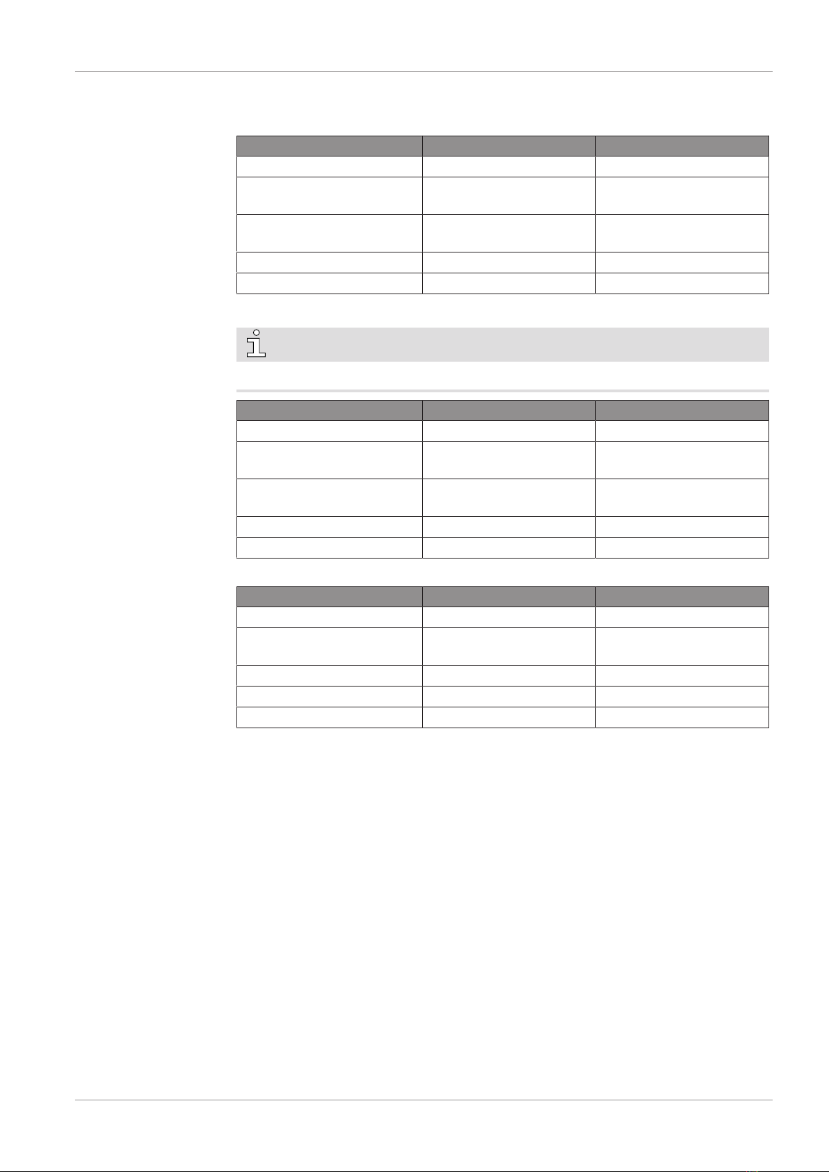
Below, the default warnings and alarms thresholds:
– for the R5 RA 0760 A PLUS vacuum pumps:
Signal type Warning (level 1) Alarm (level 2)
Exhaust gas temperature n/a >110°C
Inlet pressure >800 hPa (mbar)
for 15 minutes
>800 hPa (mbar)
for 30 minutes
Oil temperature >90°C with mineral oil
>110°C with synthetic oil
>110°C with mineral oil
>130°C with synthetic oil
Exhaust pressure >1400 hPa (mbar) abs. >1500 hPa (mbar) abs.
Electrical cabinet temperature >50°C for 30 seconds >50°C for 60 seconds
– for the R5 RA 1000-1600 A PLUS vacuum pumps:
NOTE
Mineral oil available only with water-cooling for RA 1600 A PLUS.
Signal type Warning (level 1) Alarm (level 2)
Exhaust gas temperature n/a >110°C
Inlet pressure >800 hPa (mbar)
for 15 minutes
>800 hPa (mbar)
for 30 minutes
Oil temperature >90°C with mineral oil
>120°C with synthetic oil
>110°C with mineral oil
>130°C with synthetic oil
Exhaust pressure >1400 hPa (mbar) abs. >1500 hPa (mbar) abs.
Electrical cabinet temperature >50°C for 30 seconds >50°C for 60 seconds
– for the COBRA NX 0950 A PLUS vacuum pump:
Signal type Warning (level 1) Alarm (level 2)
Water flow < 8l/min for 15 seconds < 8l/min for 30 seconds
Inlet pressure >800 hPa (mbar)
for 15 minutes
>800 hPa (mbar)
for 30 minutes
Pump temperature >65°C >70°C
Exhaust pressure >150 hPa g (mbar g) rel. >200 hPa g (mbar g) rel.
Electrical cabinet temperature >50°C for 30 seconds >50°C for 60 seconds

5 | Advanced Settings
10 / 40 Pump Control Instructions R5 PLUS - COBRA PLUS_EN_en
5 Advanced Settings
NOTICE
Change factory settings.
Risk of damage to the machine!
If wrong or not allowed parameters have been set, Busch disclaims any liability for dam-
age to the machine.
• Only change parameters after Busch approval.
To consult or change advanced settings values:
• Go to “SYSTEM” > “SETTINGS”.
• Press on “Advanced Settings”.
• Enter the password ► Role 3 for visualization and/or modification, see Role and User
[►5].
>
>
>
>
>
HOME
SETTINGS
OPERATIONS
CONTACT
MAINTENANCE SYSTEM
MODEL
Date Language
Time Units
mbar / mbar g
Warnings and alarms thresholds
°C
English01 / 07 / 2021
13 : 48
ETHERNET
Advanced settings
There are four screens containing all advanced settings.

Advanced Settings | 5
Pump Control Instructions R5 PLUS - COBRA PLUS_EN_en 11 / 40
Screen 1
HOME
SETTINGS
OPERATIONS
CONTACT
MAINTENANCE SYSTEM
MODEL
Restore default settings
Press button 5s
ETHERNET
Range maxRange minInlet pressure sensor
Off
NEXT
0 mbar 1600 mbar
Press button 5s
Restore last back-up
Off
Type
SETLinearInternal sensor
External sensor Linear SET 0 mbar 1600 mbar
External sensor Off Off
High accuracy sensor
01 - 01 - 2021 - 00 : 00
SYSTEM RESTORATION
To restore factory settings:
• Hold the button “Restore default settings” for 5 seconds.
– The following parameters will be automatically restored by the system:
– Service intervals (1)
– Warning and alarm thresholds and parameters (1)
– Operating modes and parameters (all settings in the Operations / Mode and Op-
erations / Parameters menus)
(1) according to the type of oil selected in the Advanced settings menu (see screen 3)
To restore the last back-up (2):
• Hold the button “Restore last back-up” for 5 seconds.
– The complete setting of the machine will be automatically restored by the system (all
settings and parameters in the Operations, Maintenance and System menus and
their sub-menus).
(2) the local settings are automatically saved every 2 hours in the memory of the PLC.
INLET PRESSURE SETTINGS
By default, the built-in internal pressure sensor (linear sensor) is used to control the ma-
chine. An external pressure sensor can be connected to the control unit of the machine,
in order to monitor the pressure directly at the process, or to increase the measurement
accuracy.
If the built-in internal sensor is replaced by another type of sensor (at the same loca-
tion):
• Select the appropriate type of sensor and set the proper signal and measuring range
parameters, according to the data sheet of the instrument (internal sensor).
• If the new sensor has a measurement accuracy of 0.1 mbar or better, switch ON the
“High accuracy sensor” button. The display of the inlet pressure on the main screen
will be modified as follows:

5 | Advanced Settings
12 / 40 Pump Control Instructions R5 PLUS - COBRA PLUS_EN_en
High accuracy pressure sensor OFF
(standard inlet pressure sensor)
High accuracy pressure sensor ON
Displayed
accuracy
Displayed
end vacuum
Displayed
accuracy
Displayed
end vacuum
000 mbar < 5 mbar 000.0 mbar ≤ 0.1 mbar
If an additional external sensor is installed to control the machine:
• Select the appropriate type of sensor and set the proper signal and measuring range
parameters, according to the data sheet of the instrument (external sensor).
• Switch ON the “External sensor” button.
• If the new sensor has a measurement accuracy of 0.1 mbar or better, switch ON the
“High accuracy sensor” button.
NOTE
• Only one of the following functions can be activated simultaneously: “External sen-
sor” (inlet pressure sensor) and “Pressure monitoring” (inlet filter pressure sensor), see
screen 2.
NOTICE
• For the electrical connection, please refer to the chapter Electrical Connection in the
original instruction manual of the corresponding machine.
NOTICE
Replacement of the pressure sensors.
Risk of damage to the machine!
If non suitable sensors are used or if the sensors are not properly configured and con-
nected to the control unit, Busch disclaims any liability for damages to the machine.
• Only linear sensors are supported. Logarithmic sensors are not supported. For more
information contact Busch.

Advanced Settings | 5
Pump Control Instructions R5 PLUS - COBRA PLUS_EN_en 13 / 40
Screen 2
HOME
SETTINGS
OPERATIONS
CONTACT
MAINTENANCE SYSTEM
MODEL
Trigger temperature of
cooling fan
ETHERNET
60 °C
NEXT
Gas-ballast valve activation
On
PREVIOUS
Range maxRange min
Exhaust pressure
sensor
0 mbar 1600 mbar
Inlet filter pressure
sensor
Range maxRange min
0 mbar g 1600 mbar g
Off
Pressure monitoring
Trigger temperature of cooling fan (R5 PLUS with cabinet only)
• The cooling fan trigger temperature can be set in the range of 40°C to 75°C. The de-
fault setting is 60°C.
• The increase of the trigger temperature prevents water condensation in the vacuum
pump in the event of water vapor in the process gas. Under high ambient temperature
conditions, lowering the trigger temperature reduces the temperature of the control
unit and extends the lifetime of the oil.
NOTICE
Humid applications.
Risk of damage to the machine!
Do not use the machine for pumping gases with a water vapour content higher than the
water vapour capacity of the machine. Please refer to the chapter Technical Data of the
instruction manual of the machine.
• If the vapour content is higher, use an AQUA machine. For more information contact
Busch.
Gas-ballast valve activation (R5 PLUS only)
• Press the On/Off button to enable or disable the gas ballast valve. When the gas bal-
last valve is disabled in the advanced settings, the Role 1 and Role 2 users are not al-
lowed to activate it in the Operation / Parameters menu.
Inlet filter pressure sensor (R5 PLUS only)
In case of installation of the optional Inlet filter condition monitoring kit (see Optional
Accessories in the original instruction manual of the corresponding machine):
• Switch ON the “Pressure Monitoring” button.
• Check / Set the measuring range parameters according to the data sheet of the pres-
sure sensor provided in the kit.

5 | Advanced Settings
14 / 40 Pump Control Instructions R5 PLUS - COBRA PLUS_EN_en
• Set the appropriate inlet pressure differential threshold according to the application
and to the operating pressure in the “Warnings and alarms thresholds” menu, see
screen 3.
NOTE
• Only one of the following functions can be activated simultaneously: “External sen-
sor” (inlet pressure sensor) and “Pressure monitoring” (inlet filter pressure sensor), see
screen 2.
NOTICE
• For the electrical connection, please refer to the chapter Electrical Connection in the
original instruction manual of the corresponding machine.
Exhaust pressure sensor
In case of replacement of the exhaust pressure sensor:
• Check / Set the measuring range parameters according to the data sheet of the new
instrument.
NOTICE
Replacement of the pressure sensors.
Risk of damage to the machine!
If non suitable sensors are used or if the sensors are not properly configured and con-
nected to the control unit, Busch disclaims any liability for damages to the machine.
• Only linear sensors are supported. Logarithmic sensors are not supported. For more
information contact Busch.
Screen 3
HOME
SETTINGS
OPERATIONS
CONTACT
MAINTENANCE SYSTEM
MODEL
Vacuum pump model
ETHERNET
RA 0760 A PLUS
NEXT
Oil type
PREVIOUS
Cooling type
Synthetic Oil Water cooling
PLUS Master control
Off

Advanced Settings | 5
Pump Control Instructions R5 PLUS - COBRA PLUS_EN_en 15 / 40
Vacuum pump model
• In case of retrofit of a PLUS control unit, the vacuum pump model can be selected in
the Advanced settings.
NOTICE
Wrong model of vacuum pump.
Risk of damage to the machine!
The selection of a different model of vacuum pump will automatically modify the operat-
ing parameters of the machine.
• Make sure that the vacuum pump model selected in the advanced settings menu cor-
responds to the model indicated on the nameplate of the machine.
Oil type
• In case of use of a different type of oil (mineral or synthetic) than the type of oil indi-
cated on the nameplate of the machine, select the required.
WARNING
Wrong oil type.
Risk of damage to the machine!
• The selection of a different type of oil will automatically modify the oil temperature
warning and alarm threshold and the oil service interval, according to the prescription
of this Instruction manual of the vacuum pump.
• Make sure that the type of oil selected in the advanced settings menu corresponds to
the oil filled in the machine.
Cooling type
• After installation of a heat recovery kit (water cooling), change the cooling type ac-
cordingly.
PLUS Master control
NOTE
This mode is not yet available for the COBRA NX 0950 A PLUS vacuum pump.
NOTICE
Interconnecting PLUS vacuum pumps.
Risk of damage to the machines!
• When using PLUS Master Control, use only PLUS machines of same type/size.
The PLUS Master control makes it possible to interconnect several PLUS units and makes
them work together optimally from the point of view of pressure regulation and overall
power consumption and operating hours.
• Switch ON the PLUS Master control button to activate this function.

5 | Advanced Settings
16 / 40 Pump Control Instructions R5 PLUS - COBRA PLUS_EN_en
NOTICE
Installation, settings and operation of the pumps in PLUS Master control mode.
This mode requires the PLUS vacuum pumps to be interconnected with each other via
an Ethernet connection. A total number of 2 to 6 PLUS pumps is supported.
• For more information, please refer to the specific “PLUS Master control” instruction
manual, art. no. 0870232791.
Screen 4
HOME
SETTINGS
OPERATIONS
CONTACT
MAINTENANCE SYSTEM
MODEL ETHERNET
NEXTPREVIOUS
Pressure control settings
First set of parameters
Pressure
range 0 - 125 mbar
0.40
Kp :
Tn :
Tv : 0.00
6.00
Pressure
range
Second set of parameters
Factory settings
125 - 400 mbar
0.10
Kp :
Tn : 3.00
0.00
Tv :
PID Control
This menu gives access to the parameters of the pressure regulation (used to control the
machine in pressure control mode):
• P = Proportional gain
• I = integral time
• D = Derivate time
By default, two sets of parameters are programmed in the control unit of the machine:
End vacuum ≤ inlet pressure < 125 mbar 125 mbar ≤ inlet pressure < 400 mbar
P I D P I D
0.4 6 0 0.1 3 0
The modification of the PID parameters is possible, in order to adjust the reactivity / sta-
bility of the machine and fine tune the pressure control to each application and each pro-
cess requirement.
•To change the PID settings:
– Turn on the machine and activate the pressure control mode, see sub-chapter Pres-
sure Control in the instruction manual of the machine.
– Start the process and set the required target pressure.
– Click on the value(s) to be modified (PID, switching pressure between the two sets of
parameters) and type the new value(s).

Advanced Settings | 5
Pump Control Instructions R5 PLUS - COBRA PLUS_EN_en 17 / 40
– The system will dynamically use the new parameters. Test and adjust the settings un-
til the system achieves the required performance.
•To restore the factory settings:
– Press the “Factory settings” button.
NOTICE
Wrong PID settings
Risk of loss of performance!
Selecting inappropriate PID settings can affect system performance.
• Make sure that the pressure control is effective at each step of the process and restore
factory settings if necessary.

6 | Service Interval Configuration
18 / 40 Pump Control Instructions R5 PLUS - COBRA PLUS_EN_en
6 Service Interval Configuration
NOTICE
Change factory settings.
Risk of damage to the machine!
If wrong or not allowed parameters have been set, Busch disclaims any liability for dam-
age to the machine.
• Only change parameters after Busch approval.
To change maintenance intervals:
• Go to “MAINTENANCE” > “SERVICE”.
• Press the "Set" button of the interval value to be modified.
• Enter the password ► Role 3 only, see Role and User [►5].
• Change the value according to the customer application.
HOME
HISTORY
OPERATIONS
SERVICE
MAINTENANCE SYSTEM
TREND
Reset
Reset
Set
Set
Next exhaust filters service
Next oil service Oil service interval
Exhaust filters service interval
NEXT
3993 h
3993 h 4000 h
4000 h
Last service:
00.00.0000 0 Running hour(s)
Last service:
00.00.0000 0 Running hour(s)

Remote Control | 7
Pump Control Instructions R5 PLUS - COBRA PLUS_EN_en 19 / 40
HOME
HISTORY
OPERATIONS
SERVICE
MAINTENANCE SYSTEM
TREND
Reset
Reset
Set
Set
Next inlet filter service
Next overhaul Overhaul interval
Inlet filter service interval
3993 h
57 month(s) 60 month(s)
4000 h
Last service:
00.00.0000 0 Running hour(s)
Last service:
00.00.0000
PREVIOUS
7 Remote Control
The machine can be remotely controlled via an analog, digital or modbus input when the
control mode “Remote” is activated. By default, the control mode is “Local”.
To access the control mode menu:
• Go to “OPERATIONS” > “MODE”.
• Access to the third screen.
PREVIOUS
HOME
MODE
OPERATIONS
PARAMETERS
MAINTENANCE SYSTEM
WEEK PLANNER
Control mode
Manual Auto
Modbus control
Start / Stop
Local
Remote
Analog speed control
Digital speed control
NOTE
Analog or digital modes allow the control of the machine speed.
Remote mode allows full control and monitoring of the machine.

7 | Remote Control
20 / 40 Pump Control Instructions R5 PLUS - COBRA PLUS_EN_en
7.1 Start / Stop
To remotely start and stop the machine via a digital input:
• Select the control mode “Remote/Start/Stop”.
Control mode
Remote
Local Manual Auto
Start / Stop Digital speed control
Modbus controlAnalog speed control
• Connect your system to the terminal board located inside the control unit.
• Consult the chapter Terminal Board Schematic [►26].
NOTE
This function only starts and stops the machine remotely.
The local settings will be applied to control the machine.
7.2 Digital Speed Control
To control the machine via a combination of two digital inputs (preset speed):
• Select the control mode “Remote/Digital speed control”.
Control mode
Remote
Local Manual Auto
Start / Stop Digital speed control
Modbus controlAnalog speed control
• Connect your system to the terminal board located inside the control unit.
• Consult the chapter Terminal Board Schematic [►26].
Other manuals for R5 PLUS
2
This manual suits for next models
4
Table of contents
Other BUSCH Controllers manuals
Popular Controllers manuals by other brands

Truma
Truma MonoControl CS operating instructions

Intelligent lighting
Intelligent lighting DMX-240A, DMX-240B user manual

JamMate
JamMate PRIMUS a25 Quick start user guide

Mitsubishi Electric
Mitsubishi Electric MELSEC iQ-R Series Programming manual

Cognex
Cognex In-Sight VC200 reference guide

Danfoss
Danfoss VLT Automation VT Drive FC 322 Programming guide