Bushnell 20-4124 User manual

2
Model: 20-4124/20-4124EU
LIT. #: 98-0879/01-07
4-12x42
Laser Rangefinder Riflescope

1 2
CONTENTS
English
Français
Español
Deutsch
Italiano
Português
2 - 28
29 - 58
59 - 86
87 - 115
116 - 141
142 - 167
Bushnell Yardage Pro 4-12x42 Laser Rangefinder Riflescope (204124)
Congratulations on your purchase of the Bushnell®YARDAGE PRO®LASER RANGEFINDER
RIFLESCOPE. The YARDAGE PRO®LASER RANGEFINDER RIFLESCOPE is a precision Laser
Rangefinding optical instrument designed to provide many years of enjoyment. This booklet will help
you achieve optimum performance by explaining its adjustments and features as well as how to care
for this instrument. To ensure optimal performance and longevity, please read these instructions before
using your YARDAGE PRO®LASER RANGEFINDER RIFLESCOPE.
INTRODUCTION
Glass—Range—Adjust—all with one product! Bushnell has combined a premium 4-12x42mm
riflescope with 3.5 inch eye-relief, a digitally advanced precision laser rangefinder providing distances
from 30-800 yards, and a bullet drop compensator into one outstanding product. Fully Multi-Coated
Optics deliver optimum brightness and color fidelity. The laser rangefinder is easily activated with
an infrared remote trigger pad. Bullet-drop turrets eliminate hold-over guesswork. Simply install the
turret that matches your caliber and load. When the range appears in the reticle, simply adjust it to the
corresponding distance and hold dead-on. 100% waterproof / fogproof construction, Mil-dot reticle,
standard and SCAN modes, and operates on 3-volt battery (included).
ENGLISH

3 4
RANGING ACCURACY
The ranging accuracy of the YARDAGE PRO®LASER RANGEFINDER RIFLESCOPE is plus or
minus one yard / meter under most circumstances. The maximum range of the instrument depends on
the reflectivity of the target. The maximum distance under optimal conditions is 800 yards / 732 meters.
Note: You will get both longer and shorter maximum distances depending on the reflective properties
of the particular target and the environmental conditions at the time the distance of an object is being
measured. The color, surface finish, size and shape of the target all affect reflectivity and range. The
brighter the color, the longer the range. White is highly reflective, for example, and allows longer ranges
than the color black, which is the least reflective color. A shiny finish provides more range than a dull
one. A small target is more difficult to range than a larger target. The angle to the target also has an
effect. Shooting to a target at a 90 degree angle (where the target surface is perpendicular to the flight
path of the emitted energy pulses) provides good range while a steep angle on the other hand, provides
limited ranging. In addition, lighting conditions (e.g. the amount of sunlight) will affect the ranging
capabilities of the unit. The less light (e.g. overcast skies) the farther the unit’s maximum range will be.
Conversely, very sunny days will decrease the unit’s maximum range.
HOW DOES IT WORK?
Previously, you had to estimate distance to a target by means of a riflescope reticle, calculating post-
to-post intervals with more or less exact results. Now you can measure the exact distance to a target
with dead-on precision instantaneously. With the YARDAGE PRO®LASER RANGEFINDER
RIFLESCOPE, you just activate the unit by pressing the infrared remote and the laser rangefinder emits
invisible, eye safe, infrared energy pulses. Sophisticated digital technology instantaneously calculates
distances by measuring the time it takes for each pulse to travel from the rangefinder, to the target, and
back resulting in instantaneous and accurate readings within the field-of-view.

5 6
Please Note:
This product is specified to function at 14° F (-10° C). However,
all electronic devices are susceptible to operating issues at prolonged
exposure to cold temperatures. Any operating issues that occur due to
temperature extremes should be temporary in nature. To help prevent
this, it is recommended you install a new battery when preparing to use
the device in temperatures at, or below, freezing.
(Figure 1)
Elevation Adjustment (1.8) Windage Adjustment (1.7)
Yard/Meter Button (1.3)
Battery Cover (1.1)
Locking Screw
Eyepiece
Fast Focus (1.4)
Objective Lens
Objective Tube
Remote Sensor (1.6) Main Power Button (1.2)
Mounting
Ocular Lens
Power Change Ring (1.5)

7 8
GETTING STARTED
INSERTING THE BATTERY
Remove the battery compartment cover (Figure 1.1) by loosening the battery compartment locking
screw with a coin. Insert one CR-2 3-volt lithium battery with polarity (+ and -) as indicated inside
the compartment. Replace the battery compartment cover and secure by tightening the battery
compartment locking screw.
Note: The battery will provide approximately 5,000 ranges. Remove the battery from the riflescope if
it is not going to be used for longer than one month.
(Figure 2) Infrared Remote Trigger Pad
BATTERY LIFE INDICATOR
OPERATIONAL SUMMARY
WARNING: This laser rangefinder riflescope should never be used as a substitute for a binocular,
spotting scope, or measuring device only, as it may result in your inadvertently pointing the gun
at another person. Before using this device, always remember it is mounted on a firearm and all
firearm safety precautions apply. When handling firearms, always keep the muzzle pointed in a safe
direction.
While looking through the riflescope, always depress the main power button (Figure 1.2) once to turn
the unit on. You can now use the infrared remote trigger pad (Figure 2) to activate the laser and
Battery: Full Half Battery: It is recommended
that the battery be replaced.
Power on Screen

9 10
in-view LED display (Figure 3). NOTE: If the unit has not been used for two or more hours, the
main power button will need to first be depressed in order to use the infrared remote trigger pad. Aim
the laser rangefinder at a target at least 30 yards away, depress and hold the power button or infrared
remote trigger pad down until range reading is displayed. Release the power button or remote trigger
pad. Note: Once activated, the laser rangefinder’s LED will remain active and display the last distance
measurement for 8 seconds. You can depress the power button / remote trigger pad again at any time
to distance to a new target. Once the device is on and the power button or remote trigger pad is held
down for over 2 seconds, the device transitions to SCAN mode. This mode allows the range to be
continuously updated for as the power button / remote trigger pad is depressed. As with any laser
device, it is not recommended to directly view the emissions for long periods of time with magnified
lenses.
If three horizontal line (---) appear (Figure 4), this indicates that the unit could not measure the distance
properly for a number of reasons (i.e. target too far away, intense reflection, unit not aimed directly
at target, etc). Three lines, one on top of another in a vertical arrangement (Figure 5) will appear
indicating that the unit is measuring and the distance in yards or meters will appear (Figure 6).
(Figure 3) (Figure 4) (Figure 5) (Figure 6)
If the unit of measure appears in Yards (Y) and you would like to switch the Meters (M), simply press
the Yards / Meters button (Figure 1.3) portion of the main POWER button. Conversely, when the
readout is in meters, it can be switched to yards by the same process.
INFRARED REMOTE TRIGGER PAD
An infrared remote trigger pad (Figure 2) is included with the product. It was designed to attach to the
forearm of the rifle and will work for either right or left hand shooters. It allows the user to maintain
a stable shooting position while operating the laser rangefinder. The red triangle on the remote trigger
must be faced toward the shooter and be placed on the forearm of the rifle for it to work properly and
needs to be positioned within the 6 inch space outlined in Figure 7 so that it can properly communicate
with the infrared sensor (Figure 1.6). The remote trigger operates on one CR2016 watch battery. To
replace this battery, open the cover with a small screw driver, remove existing battery and replace with
a new one and replace cover.
(Figure 7) 6 inches / 152mm

11 12
NOTE: The electronics are set to automatically shut off after two hours of inactivity. Therefore, to
re-instate use of the infrared remote trigger pad, the main power button (Figure 1.2) must first be
depressed.
EYEPIECE FOCUSING
This adjusts the focus so that the reticle (cross hairs) appears sharp to your eyes. All Bushnell laser
rangefinder riflescopes are focused at the factory for 20/20 or corrected vision. If the reticle appears
sharp, no adjustment is needed. If the reticle appears unsharp, adjust as follows.
The FAST FOCUS eyepiece (Figure 1.4) is designed to provide a precise fast focus. Simply look at a
distant object for several seconds without using your scope. Then, shift your vision quickly, looking
though the scope at a plain background. Turn the fast-focus eyepiece clockwise or counter clockwise
until the reticle pattern is sharp and clear.
WARNING: Never look at the sun through the laser rangefinder riflescope (or any other optical
instrument). It may permanently damage your eye.
VARIABLE POWER ADJUSTMENTS
To change magnification, simply rotate the Power Change Ring (Figure 1.5) to align the desired number
on the power scale with the Red Arrow Indicator.
When still-hunting or stalking game, a variable scope should be set to the lowest power. You then have
the widest field of view for quick shots at close range. Higher powers should be reserved for precise
long-range shots.
WARNING: This laser rangefinder riflescope should never be used as a substitute for a binocular,
spotting scope, or measuring device only, as it may result in your inadvertently pointing the gun
at another person. Before using this device, always remember it is mounted on a firearm and all
firearm safety precautions apply. When handling firearms, always keep the muzzle pointed in a safe
direction.
MOUNTING (See Figure 8)
To achieve the best accuracy from your rifle, your Bushnell scope must be mounted properly. (We
strongly recommend that those unfamiliar with proper procedures have the scope mounted by a
qualified gunsmith). Should you decide to mount it yourself:
Use the enclosed mount system. The mounts are made to fit the weaver style dovetail system. Before
mounting the scope, determine approximately where you would like it to be on the rifle. The slots on
the bottom of the riflescope allow you great flexibility in mounting the scope forward or to the rear.
WARNING: If the scope is not mounted far enough forward, its rearward motion may injure the
shooter when the rifle recoils.

13 14
The front mount has a key that fits into the slots on the riflescope dovetail. Choose the appropriate
slot and attach the front mount securely with the two scope dovetail screws. The rear mount does not
have a key allowing it to slide forward or backward on the dovetail of the riflescope to fit. Loosely
place it on the riflescope dovetail – leave the two screws loose for now so that the mount can slide on
the dovetail.
Place the riflescope on the rifle, fitting the front and rear mounts to the weaver bases. Space the mounts
as far apart as possible to provide stability. Lightly tighten the screws holding the mounts to the weaver
bases.
Now look through the scope in your normal shooting position. Adjust the scope
(either forward or backward with the mounts) until you find the
furthest point forward (to insure maximum eye relief)
that allows you to see a full field of view.
Tighten the mounting screws
as tight as possible.
(Figure 8)
Key
Front Mount
Rear Mount
ELEVATION AND WINDAGE ADJUSTMENT
Your Bushnell®YARDAGE PRO®LASER RANGEFINDER RIFLESCOPE features finger-adjustable,
audible-click elevation and windage adjustments. If the point of impact of the bullet deviates from the
aiming point, then adjustment of the windage and elevation must be made.
To adjust windage, remove the threaded cap from the Windage Adjustment (Figure 1.7).
Grasp the knob and turn it in the appropriate “L” (Left) and/or “R” (Right) direction indicated by the
arrows. Each “click” or increment on the adjustment scale ring will change the bullet impact by 1/4”
Minute of Angle. 1/4 MOA corresponds to 1/4 inch at 100 yards, 1/2 inch at 200 yards, 3/4 inch at
300 yards and so on.
RESETTING THE ADJUSTMENT SCALE RING
This step is not necessary, but, for future reference, you may want to realign the zero marks on the
Adjustment Scale Rings with the index dots.
- Using a coin, remove the center screw from the windage or elevation control. Lift the turret up being
careful not to rotate it.
- Position the turret to zero, or where you would like it to be.
- Replace and tighten the center screw, making sure you do not rotate the turret.

15 16
BORE SIGHTING
Bore sighting is a preliminary procedure to achieve proper alignment of the scope with the
rifle bore. It is best done using a Bushnell Bore Sighter. If a bore sighter is not available,
it can be done as follows: Remove the bolt and sight through the gun barrel at a 100 yard
target. Then sight through the scope and bring the crosshairs to the same point on the target.
SIGHTING IN RIFLE AT THE RANGE
- Remove the elevation cap. If the standard elevation turret is not installed, remove the BDC turret and
install it. This is done by using a coin to unscrew the retaining screw in the center of the turret. Grasp
knurl at top of the Turret and lift upward, disengaging turret from the elevation adjustment pin. Reverse
to install a new turret.
- Sight-in the rifle, firing a group of at least three shots at 100 yard target. Note the relationship of the
center of group to the center or the target. Rotate the turret the required number of clicks to make the
necessary point of impact move. Follow with the windage adjustment to bring shots to center of target.
Fire another group to see if proper adjustment has been made. Repeat as necessary until center of group
is in center of target.
- Once the rifle is sighted-in at 100 yds, you may install the proper BDC Turret for your caliber and
bullet weight (see “SELECT PROPER TURRET” below).
(NOTE: When the selected BDC turret is installed, the elevation cap cannot be used. If the standard
elevation turret is installed, the cap can be threaded onto the scope).
POPULAR CAILBER & LOAD COMBINATIONS BALLISTIC
GROUP
Federal Cartridge.224 dia. 22-250 Rem, 55 gr. Bear Claw at 3600 fps G
Federal Cartridge.224 dia. 22-250 Rem, 60 gr. Partition at 3500 fps F
Remington Arms .224 dia. 22-250 Remington Arms , 50 gr. V-Max at 3725 FPS H
Remington Arms .224 dia. 22-250 Remington Arms , 55 gr. PSP at 3680 FPS G
Winchester .224 dia. 22-250 Rem, 55 gr. Ballistic Silvertip at 3680 FPS H
Winchester .224 dia. 22-250 Rem, 55 gr. PSP at 3680 FPS G
Federal Cartridge .277 dia. 270 Win, 150 gr. Ballistic Tip at 3060 fps F
Federal Cartridge .277 dia. 270 Win, 150 gr. Partition at 3000 fps F
Remington Arms .277 dia. 270 Win, 140 gr. PSPCL Ultra at 2925 FPS E
Remington Arms .277 dia. 270 Win, 150 gr. SPCL at 2850 FPS D
Winchester .277 dia. 270 Win, 150 gr. Partition Gold at 2930 FPS E
Winchester .277 dia. 270 Win, 150 gr. PP-Plus at 2950 FPS E
Federal Cartridge .308 dia. 30-06 Spring, 180 gr. AccuBond at 2700 FPS D
Federal Cartridge .308 dia. 30-06 Spring, 180 gr. Bear Claw at 2700 FPS D
Remington Arms .308 dia. 30-06 Springfield, 180 gr. A-Frame at 2700 FPS D

17 18
SELECTING THE PROPER TURRET
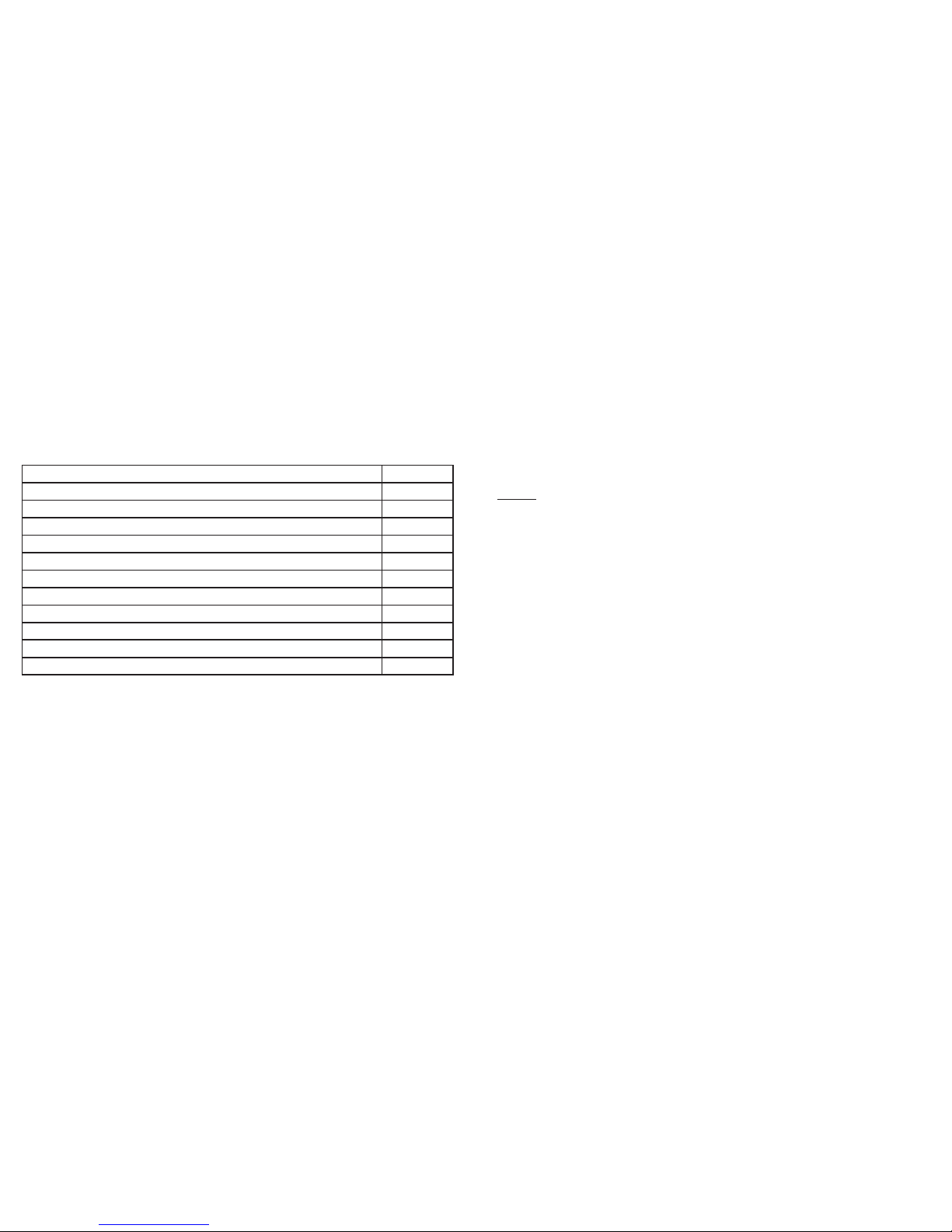
Each riflescope comes complete with seventeen interchangeable turrets. Eight of these turrets are
calibrated with distance in “yards” markings and eight for “meters” covering most popular factory
cartridges. The seventeeth turret has no distance calibration but is provided so that you may make your
Remington Arms .308 dia. 30-06 Springfield, 180 gr. BRPT at 2700 FPS D
Winchester .308 dia. 30-06 Sprg, 180 gr. FailSafe at 2700 FPS D
Winchester .308 dia. 30-06 Sprg, 180 gr. Partition Gold at 2750 FPS D
Federal Cartridge.308 dia. 300 WSM, 180 gr. AccuBond at 2960 fps F
Federal Cartridge.308 dia. 300 WSM, 180 gr. Bear Claw at 3025 fps F
Winchester .308 dia. 300 WSM, 180 gr. Ballistic Silver Tip at 3010 FPS F
Winchester .308 dia. 300 WSM, 180 gr. Fail Safe at 2970 FPS F
Remington Arms .308 dia. 300 R.S.A.U.M., 180 gr. PSPCL Ultra at 2960 FPS E
Remington Arms .308 dia. 300 Wby Mag, 180 gr. PSPCL at 3120 FPS F
Lazzeroni Arms .308 dia., 7.82 Patriot, 180 gr. Partition Lubed at 3184 FPS H
Lazzeroni Arms .308 dia., 7.82 Warbird, 150 gr. Lazerhead at 3775 FPS H
Lazzeroni Arms .308 dia., 7.82 Warbird, 168 gr. HPBT MatchKing at 3550 FPS H
own distance markings fit any cartridge not covered. From the Ballistic Chart below (or the complete
charts on the CD), select the proper turret for use with your caliber and bullet weight combination.
Example: You have a .300 WSM and are shooting the following Winchester brand load: 180 gr. Ballistic
Silver Tip bullet at 3010 FPS muzzle velocity. This combination falls under Ballistic group “F”, so you
would use the turret marked “F” in either yards or meters.
What if your caliber is not listed?
While we have taken great care to include as many calibers and brand names in our ballistic tables, new
loads are always being developed. In additon, some shooters load their own ammunition with unique
ballistic characteristics. If you cannot find your load in the ballistic tables, you can still use the BDC
feature.
Option 1:
As above, sight in your rifle at 100 yds with the standard turret. Then shoot the rifle, without adjusting
the riflescope, at 300 yds. Measure the bullet drop from the point of aim. Using this drop, select the
ballistic group from below. If you will be shooting at longer distances then you may want to check the
bullet drop at 500 yds. Because there is enormous variation in rifle barrels, chambers, and hand loads,
you should thoroughly test the ballistic setting before actual hunting. You may need to move up or down
one group depending upon your tests.
Option 2:
Includedwiththe markedturretsis ablankturret. After yourrifleis sightedinat 100yds,replacethestandard
turret with the blank turret. Without adjusting the elevation, shoot the rifle at various distances up to the

19 20
maximum distance needed. Measure the bullet drop at each distance and then convert the drop into moa.
Multiplythemoaby 4. Usingthis number,count thenumberof tickmarkson thedial andmarkthe distance.
Example: Suppose you have a bullet drop of 9 inches at 300 yds. This is a drop of 3 moa. Since the
clicks are ¼ moa, the drop for 300 yds would be 12 tick marks.
USING MIL DOTS
Your new Bushnell®YARDAGE PRO®LASER RANGEFINDER RIFLESCOPE contains a mil-dot
reticle. Since the riflescope already contains an integrated laser rangefinder, it is not likely that you will
If Bullet Drop is: @300 yds @300 m @500 yds @500 m
Use:
A 25-31 inches 63-79 cm 114-146 inches 291-370 cm
B 20-25 inches 50-63 cm 88-114 inches 225-291 cm
C 16-20 inches 40-50 cm 72-88 inches 182-225 cm
D 13-16 inches 34-40 cm 61-72 inches 155-182 cm
E 12-13 inches 30-34 cm 55-61 inches 139-155 cm
F 10-12 inches 25-30 cm 47-55 inches 119-139 cm
G 8-10 inches 20-25 cm 39-47 inches 99-119 cm
H Less than 8 inches Less than 20 cm Less than 39 inches Less than 99 cm
need the mil dot for measuring distance, but is useful for precise leads for moving targets and exact
compensation for shooting in a crosswind. There are certain situations that may not allow one enough
time to range to an animal, and having the mil-dot reticle is second alternative in measuring distance.
The middle of this reticle contains four evenly spaced mil-dots arrayed outward vertically and
horizontally from the center. Actually, because the very center dot was left out to allow clear aiming, the
reticle represents five mils in any direction.
One mil is the space from center-dot to center-dot. One-half and one-quarter mils are easy to estimate
mentally; with practice, you can measure tenths of mils for the most exact ranging.
RANGING WITH YOUR MIL-DOT RETICLE
The mil is an angular measurement— a milliradian—which equals almost precisely one yard at 1000
yards, or one meter at 1000 meters. This proportional relationship makes possible a simple formula to
compute distances:
The Measured Object’s Width Or Height In Yards x 1000
= Range In Yards
Object’s Width Or Height In Mils
This formula works equally well with meters, but don’t mix meters and yards: Measure the object in yards
to find the distance in yards, use meters to yield distances in meters.

21 22
Looking through your scope at the synchronized magnification setting, select an object at the distance you
want to range -- an object whose width or height you know or can estimate accurately. Man-made objects
of uniform size, such as fence posts, are best, but any object of known dimensions will do. Measure the
object’s height or width carefully in mils, compute it according to the formula and you will find its range.
Support your rifle and be precise when measuring objects; any measuring error causes an error in the
computed range. Equally, incorrectly estimating the object size results in a proportional range error.
Here’s an example: A coyote is sunning himself in a snowfield beside a fencepost; having crossed the
fence earlier, you know that the post is four feet high, or 1.33 yards. The fencepost measures 2.5 mils in
your reticle.
1.33 yards x 1000 1330
= = 532 Yards
2.5 mils 2.5
Since this is a variable power scope and the reticle stays the same size no matter the magnification, it must
be set at the 12x index dot to synchronize the mil-dot size for ranging.
CALCULATING HOLDS FOR WIND AND MOVING TARGETS
Your horizontal mil dots provide a precise way of holding for crosswinds and target movement. Just look
in your cartridge’s wind drift and moving target tables to determine the exact holds for different distances.
The accompanying table lists one-mil widths from 100 to 600 yards, so you can calculate how many mils
to hold right or left when firing in a crosswind, or engaging a moving target.
MIL WIDTH FOR WIND AND MOVING TARGET LEADS
Distance One Mil at This Distance (Inches)
100 Yards 3.6” (0.1 Yard)
200 Yards 7.2” (0.2 Yard)
300 Yards 10.8” (0.3 Yard)
400 Yards 14.4” (0.4 Yard)
500 Yards 18.0” (0.5 Yard)
600 Yards 21.6” (0.6 Yard)
1. One mil is the distance between center of dots. It’s easy to measure in half-mils or even quarter-mils
but with practice you can measure tenths of a mil.
2. 6x - Object measures half as large as 12x, so calculate the distance, then divide by half.
3. 12x - Synchronized setting for this mil-dot reticle. Calculate as normal.
MAINTENANCE
Your Bushnell®YARDAGE PRO®LASER RANGEFINDER RIFLESCOPE, though amazingly tough,
is a precision instrument that deserves reasonably cautious care.

23 24
1. When cleaning the lenses, first blow away any dry dirt and dust, or use a soft lens brush. Fingerprints
and lubricants can be wiped off with lens tissue, or a soft clean cloth, moistened with lens cleaning
fluid.
WARNING: Unnecessary rubbing or use of a course cloth may cause permanent damage to the lens
coatings.
2. All moving parts of the scope are permanently lubricated. Do not try to lubricate them.
3. No maintenance is needed on the scope’s outer surface, except to occasionally wipe off dirt or
fingerprints with a soft cloth.
4. Use lens covers whenever it is convenient.
STORAGE
Remove the battery from the riflescope if it is not going to be used for longer than one month.
Avoid storing the scope in hot places, such as the passenger compartment of a vehicle on a hot day. The
high temperature could adversely affect the lubricants and sealants. A vehicle’s trunk, a gun cabinet or
a closet is preferable. Never leave the scope where direct sunlight can enter either the objective or the
eyepiece lens. Damage may result from the concentration (burning glass effect) of the sun’s rays.
TROUBLE SHOOTING TABLE
If unit does not turn on - LED does not illuminate:
• Depress main power button on the riflescope first, and then the infrared remote switch.
• Check and if necessary, replace battery.
• Check battery within the infrared remote switch, and if necessary, replace its’ battery.
If unit powers down (display goes blank when attempting to power the laser):
• The battery is either weak or low quality. Replace the battery with a good quality lithium battery.
• The last range reading does not need to be cleared before ranging another target. Simply aim at the
new target using the reticle, depress the power button and hold until new range reading is displayed.
If target range cannot be obtained:
• Make sure LED is illuminated.
• Make sure that the power button is being depressed
• Make sure that nothing, such as your hand or finger, is blocking the objective lenses (lenses closest to
the target) that emit and receive the laser pulses.
• Make sure unit is held steady while depressing power button.
Specifications, instructions, and the operation of these products are subject to change without notice.
This product complies with CFR 21 1040.10. Class 1 laser product.

25 26
SPECIFICATIONS
Length (in/mm): 13 / 330
Weight (Oz /g): 25 / 708
Accuracy: +/- 1 yard / meter
Minimum and Maximum Ranging Performance: 30-800 Yards/ 27-732 Meters
Magnification: 4-12X
Objective Size: 42mm
Fully Multi-Coated Optics
Power Source: 3 volt lithium battery (included)
FOV (feet@ 100 yards / meters@ 100 meters): 26@4x / 8.7@4x
8.5@12x / 2.8@12x
Total Eye Relief (inches / mm): 3.5 / 89
Windage & Elevation Click Value .25
Waterproof / Fogproof
Parallax-free at a distance of 100 yards
Temperature range for operation: -10° to 50° C / 14° to 122° F
Specifications and designs are subject to change without any notice or obligation on the part of the
manufacturer.
TWO-YEAR LIMITED WARRANTY
Your Bushnell®product is warranted to be free of defects in materials and workmanship for two years after the date of purchase. In the event of a defect under this
warranty, we will, at our option, repair or replace the product, provided that you return the product postage prepaid. This warranty does not cover damages caused by
misuse, improper handling, installation, or maintenance provided by someone other than a Bushnell Authorized Service Department.
Any return made under this warranty must be accompanied by the items listed below:
1) A check/money order in the amount of $10.00 to cover the cost of postage and handling
2) Name and address for product return
3) An explanation of the defect
4) Proof of Date Purchased
5) Product should be well packed in a sturdy outside shipping carton, to prevent damage in transit, with return postage prepaid to the address listed below:
IN U.S.A. Send To: IN CANADA Send To:
Bushnell Outdoor Products Bushnell Outdoor Products
Attn.: Repairs Attn.: Repairs
8500 Marshall Drive 25A East Pearce Street, Unit 1
Lenexa, Kansas 66214 Richmond Hill, Ontario L4B 2M9
For products purchased outside the United States or Canada please contact your local dealer for applicable warranty information. In Europe you may also contact
Bushnell at: BUSHNELL Outdoor Products Gmbh
European Service Centre
MORSESTRASSE 4
D- 50769 KÖLN
GERMANY
Tél: +49 (0) 221 709 939 3
Fax: +49 (0) 221 709 939 8
This warranty gives you specific legal rights.
You may have other rights which vary from country to country.
©2007 Bushnell Outdoor Products

27 28
FCC NOTE
This equipment has been tested and found to comply with the limits for a Class B digital device,
pursuant to Part 15 of the FCC Rules. These limits are designed to provide reasonable protection against
harmful interference in a residential installation. This equipment generates, uses and can radiate radio
frequency energy and, if not installed and used in accordance with the instructions, may cause harmful
interference to radio communications. However, there is no guarantee that interference will not occur
in a particular installation. If this equipment does cause harmful interference to radio or television
reception, which can be determined by turning the equipment off and on, the user is encouraged to try
to correct the interference by one or more of the following measures:
• Reorient or relocate the receiving antenna.
• Increase the separation between the equipment and receiver.
•
Connect the equipment into an outlet on a circuit different from that to which the receiver is connected.
• Consult the dealer or an experienced radio/TV technician for help.
Shielded interface cable must be used with the equipment in order to comply with the limits for a digital
device pursuant to Subpart B of Part 15 of FCC Rules.
Specifications and designs are subject to change without any notice or obligation on the part of the
manufacturer.

29 30
4-12x42
Laser Rangefinder Riflescope
FRANÇAIS
Lunette de visée Bushnell à télémètre laser Yardage Pro 4-12x42
Nous vous félicitons d’avoir acheté la LUNETTE DE VISÉE Bushnell®À TÉLÉMÈTRE LASER
YARDAGE PRO®. LA LUNETTE DE VISÉE À TÉLÉMÈTRE LASER YARDAGE PRO®est
un instrument de télémétrie laser de précision, conçu pour vous donner de nombreuses années de
satisfaction. Ce manuel vous explique les réglages et les caractéristiques, ainsi que le soin à prendre
de cet instrument pour en obtenir une performance optimale. Pour assurer une performance et une
longévité optimales, il importe de lire ces instructions avant d’utiliser LA LUNETTE DE VISÉE À
TÉLÉMÈTRE LASER YARDAGE PRO®.
INTRODUCTION
Optique—Mesure de distance--Réglage--tout en un seul produit ! Bushnell réunit en un produit
exceptionnel une lunette de visée 4-12x42 mm de première qualité, un dégagement oculaire de 8,75
cm (3,5 po), un télémètre de précision numériquement perfectionné capable de mesurer des distances
comprises entre 27et 732 m (30 à 800 verges) et un compensateur de chute de balles. Les éléments
optiques entièrement multicouches assurent une luminosité et une fidélité de couleur optimales. Le
télémètre laser est aisément activé grâce à un déclencheur à télécommande à infrarouge. Les tourelles de
chute de balles évitent d’avoir à deviner à quelle hauteur tenir l’arme au-dessus du niveau prédéfini de la
cible. Il vous suffit d’installer la tourelle correspondant à votre calibre et de charger. Lorsque la mesure
de portée apparaît dans le réticule, réglez-le à la distance correspondante et tenez l’arme droit sur la
cible. Construction 100 % étanche / antibuée, réticule Mil-dot, modes standard et SCAN (balayage),
fonctionne avec une pile de 3 volts (incluse).

31 32
MODE DE FONCTIONNEMENT
Autrefois, il fallait estimer la distance qui vous séparait d’une cible au moyen du réticule de la lunette de
visée, en calculant les intervalles entre curseurs pour n’obtenir que des résultats plus ou moins corrects.
Désormais, vous pouvez mesurer la distance exacte qui vous sépare de la cible avec une précision absolue,
et instantanément. Avec la LUNETTE DE VISÉE À TÉLÉMÈTRE LASER YARDAGE PRO®, il vous
suffit d’activer l’appareil en appuyant sur la télécommande à infrarouge et le télémètre laser émet des
impulsions d’énergie infrarouge invisibles et sans danger pour vos yeux. Cette technologie numérique
sophistiquée permet de calculer instantanément les distances en mesurant le temps nécessaire à chaque
impulsion pour se déplacer dans les deux sens entre le télémètre et la cible, ce qui produit instantanément
des lectures précises dans votre champ de vision.
PRÉCISION DE LA MESURE DE PORTÉE
TLa précision de la mesure de portée de LA LUNETTE DE VISÉE À TÉLÉMÈTRE LASER
YARDAGE PRO®est de plus ou moins 1 verge / mètre dans la plupart des cas. La portée maximale de
l’instrument dépend de la réflectivité de la cible. Dans des conditions optimales, la distance maximum
est de 732 mètres (800 verges).
Remarque : Vous obtiendrez des distances maximales plus longues ou plus courtes, suivant le pouvoir
réfléchissant de la cible et les conditions environnementales au moment où la distance d’un objet est
mesurée. La couleur, le fini de surface, la taille et la forme de la cible affectent sa réflectivité et sa portée.
Plus vive est la couleur, plus longue est la portée. Par exemple, le blanc est extrêmement réfléchissant, et il
permet d’obtenir des portées plus longues que la couleur noire, qui est la couleur la moins réfléchissante.
Un fini brillant assure une plus grande portée qu’un fini mat Une petite cible est
(Figure 1)
plus difficile à mesurer qu’une grosse cible. L’angle de la cible a également un effet. Viser une cible à
un angle de 90 degrés (lorsque la surface de la cible est perpendiculaire à la trajectoire des impulsions
émises) permet une bonne mesure de portée alors qu’un angle aigu permet une mesure limitée. De plus,
l’éclairage (par ex., la lumière solaire) affecte la capacité de mesure de portée de l’appareil. Avec un faible
éclairage (par ex., ciel nuageux) la portée maximale de l’appareil est plus longue. En revanche, par temps
très ensoleillé, la portée maximale de l’appareil diminue.
Réglage de pointage en hauteur (1.8)
Réglage de la correction due
au vent (1.7) Bouton verges / mètres (1.3)
Couvercle du compartiment
des piles (1.1)
Vis de blocage
Oculaire
Mise au point
rapide (1.4)
Lentille d’objectif
Tube de l’objectif Télécapteur (1.6) Bouton d’alimentation
principal (1.2) Montures
Lentile
d’oculaire
Bague de changement de puissance (1.5)

33 34
POUR COMMENCER
Insérez une pile CR-2 de 3 volts au lithium ; la polarité (+ et -) est indiquée à l’intérieur du
compartiment.
Remettez le couvercle du compartiment des piles et fixez-le en resserrant sa vis de blocage.
Remarque : La pile vous permet d’effectuer environ 5 000 mesures de portée. Enlevez la pile de la lunette
de visée si cette dernière est pour rester inutilisée pendant plus d’un mois.
(Figure 2) Déclencheur à télécommande à infrarouge
Remarque :
Ce produit est spécifié fonctionner à -10° C (14° F). Toutefois, tous les ap-
pareils électroniques peuvent être sujets à des problèmes de fonctionnement en
cas d’exposition prolongée aux basses températures. Tout problème de fonc-
tionnement causé par des températures extrêmes devrait être de nature tempo-
raire. Pour éviter cela, il est conseillé de placer des piles neuves avant d’utiliser
l’appareil à 0°C ou en dessous.

35 36
Lorsque vous regardez dans votre lunette de visée, appuyez une fois sur le bouton d’alimentation
principal (Figure 1.2) pour activer l’appareil. Vous pouvez alors utiliser le déclencheur à télécommande
à infrarouge (Figure 2) pour activer le laser et l’afficheur DEL en objectif (Figure 3).REMARQUE : Si
l’appareil n’a pas été utilisé depuis deux heures ou plus, appuyez d’abord sur le bouton d’alimentation
principal afin de pouvoir utiliser le déclencheur à télécommande à infrarouge. Pointez le télémètre laser
sur une cible se trouvant à au moins 27 mètres (30 verges), appuyez sur le bouton d’alimentation ou le
déclencheur à télécommande à infrarouge sans les relâcher jusqu’à ce que la mesure de portée s’affiche.
Relâchez le bouton d’alimentation ou le déclencheur à télécommande. Remarque : Une fois activé,
la DEL du télémètre laser reste activée et affiche la dernière mesure de distance pendant 8 secondes.
Vous pouvez appuyer à nouveau à tout moment sur le bouton d’alimentation ou le déclencheur
à télécommande pour mesurer la distance qui vous sépare d’une nouvelle cible. Lorsque l’appareil
est activé et que le bouton d’alimentation ou le déclencheur à télécommande est maintenu enfoncé
pendant plus de 2 secondes, l’appareil passe en mode SCAN (balayage). Grâce à ce mode, les mesures
sont continuellement mises à jour lorsque l’on appuie sur le bouton d’alimentation ou le déclencheur
à télécommande. Comme avec n’importe quel appareil laser, il n’est pas recommandé de regarder
directement les rayons émis pendant de longues périodes avec des lentilles grossissantes.
Trois traits horizontaux (---) (Figure 4) indiquent que l’appareil n’a pas pu mesurer correctement la
distance pour un certain nombre de raisons (par ex., la cible est trop loin, la réflexion est trop forte,
l’appareil n’est pas pointé directement vers la cible, etc.). Trois traits, disposés verticalement l’un sur
l’autre (Figure 5) apparaîtront pour indiquer que l’appareil est en train de mesurer, et la distance en
verges ou en mètres s’affichera (Figure 6).
INDICATEUR DE FAIBLESSE DE PILE
SOMMAIRE DU FONCTIONNEMENT
AVERTISSEMENT: Cette lunette de visée à télémètre laser ne doit jamais servir de jumelle, de lunette SOMMAIRE
DU FONCTIONNEMENT
AVERTISSEMENT : Cette lunette de visée à télémètre laser ne doit jamais servir de jumelle, de lunette
d’observation ou d’appareil de mesure uniquement, car vous risqueriez de pointer accidentellement
l’arme vers une autre personne. Avant d’utiliser cet appareil, souvenez-vous toujours qu’il est monté
sur une arme à feu et qu’il convient de prendre toutes les précautions de sécurité relatives aux armes
à feu. Lorsque vous manipulez des armes à feu, pointez toujours le canon dans une autre direction
ne présentant pas de danger.
Pile Chargée Pile : À moitié chargée Pile : Il est conseillé de
remplacer la pile.

37 38
REMARQUE : Les pièces électroniques sont réglées pour s’arrêter automatiquement au bout de deux
heures d’inactivité. Par conséquent, pour rétablir l’usage du déclencheur, il faut tout d’abord appuyer
sur le bouton d’alimentation principal (Figure 1.2).
MISE AU POINT DE L’OCULAIRE
Ce réglage fait apparaître le réticule (croisée de fils) très net devant vos yeux. Toutes les lunettes de visée
Bushnell à télémètre laser sont mises au point à l’usine pour une vision 20/20 ou acuité visuelle corrigée.
Si le réticule apparaît net, aucun réglage n’est nécessaire. S’il n’est pas net, réglez comme suit :
L’oculaire à MISE AU POINT RAPIDE (Figure 1.4) est conçu pour assurer une mise au point précise
et rapide. Regardez simplement un objet éloigné pendant plusieurs secondes sans utiliser votre lunette.
Ensuite, passez rapidement à l’observation d’un fond uni par la lunette de visée. Tournez l’oculaire à mise
au point rapide dans le sens horaire ou antihoraire jusqu’à ce que le réticule apparaisse net et clair.
(Figure 7)
152mm /
6 pouces
(Figure 3) (Figure 4) (Figure 5) (Figure 6)
Si l’unité de mesure apparaît en verges (V) et si vous souhaitez une mesure en mètres (M), appuyez sur
la partie verges / mètres (Figure 1.3) du bouton d’ALIMENTATION principal.
De même, lorsque la lecture est en mètres, elle peut passer en verges par le même processus.
DÉCLENCHEUR À TÉLÉCOMMANDE À INFRAROUGE
Un déclencheur à télécommande à infrarouge (Figure 2) est inclus avec le produit. Il est conçu pour se
fixer sur le garde-main de votre arme et convient aussi bien aux droitiers qu’aux gauchers. Il permet à
l’utilisateur de garder une position de tir stable pendant qu’il utilise le télémètre laser. Le triangle rouge
du déclencheur à télécommande doit être tourné vers le tireur et placé sur le garde-main de l’arme
pour que celle-ci fonctionne correctement. Il doit être positionné à moins des 15 cm (6 po) indiqués
à la Figure 7 afin de pouvoir communiquer avec le capteur infrarouge (Figure 1.6). Le déclencheur
à télécommande fonctionne avec une pile de montre CR2016. Pour remplacer cette pile, ouvrez le
couvercle avec un petit tournevis, enlevez la pile existante, remplacez-la par une pile neuve et remettez
le couvercle.
This manual suits for next models
3
Table of contents
Languages:
Other Bushnell Riflescope manuals

Bushnell
Bushnell FIRST STRIKE 730005 User manual

Bushnell
Bushnell 368050 User manual

Bushnell
Bushnell 53-0021 User manual

Bushnell
Bushnell ET3124F User manual

Bushnell
Bushnell Elite Tactikal User manual

Bushnell
Bushnell HOLOsight 51-0021 User manual

Bushnell
Bushnell CF 500 Reticle User manual

Bushnell
Bushnell BALLISTIC RETICLE User manual

Bushnell
Bushnell HOLOsight 510023 User manual

Bushnell
Bushnell 2.5-10x 44mm User manual