BVA Hydraulics J11050 User manual

Printed in Taiwan
Model: J11100 & J11200
Model: J11050 & J11055
J11050-M0 rev 08/07
Mini Jacks
Instruction Manual
SFA Com anies 10939 N. Pomona Ave. Kansas City, MO 64153
Tel: 888-332-6419 * Fax: 816-891-6599
E-mail: sales@bvahydraulics.com Website: www.bvahydraulics.com
MODELS: J11050, J11055 - 5 Ton Capacity
J11100, J11200 - 10 Ton Capacity
This is the safety alert symbol. It is used to alert you to otential ersonal injury hazards.
Obey all safety messages that follow this symbol to avoid ossible injury or death.
!

Sa e these instructions. For your safety, read, understand,
and follow the information rovided with and on this jack
before using. The owner and/or o erator of this equi ment
shall have an understanding of this jack and safe o erating
rocedures before attem ting to use. The owner and/or
o erator shall be aware that the use and re air of this roduct
may require s ecial skills and knowledge. Instructions and
safety information shall be conveyed in the o erator's native
language before use of this jack is authorized. If any doubt
exists as to the safe and ro er use of this jack, remove
from service immediately.
Inspect before each use. Do not use if broken, bent, cracked,
or damaged arts (including labels) are noted. Any jack that
a ears damaged in any way, o erates abnormally or is
missing arts, shall be removed from service immediately.
If you sus ect that the jack was subjected to a shock load (a
load dro ed suddenly, unex ectedly u on it), immediately
discontinue use until the jack has been checked by a BVA
Hydraulics authorized service center (contact distributor or
manufacturer for list of Authorized Service Centers). It is
recommended that an annual ins ection be done by
qualified ersonnel. Labels and owner's manuals are
available from manufacturer.
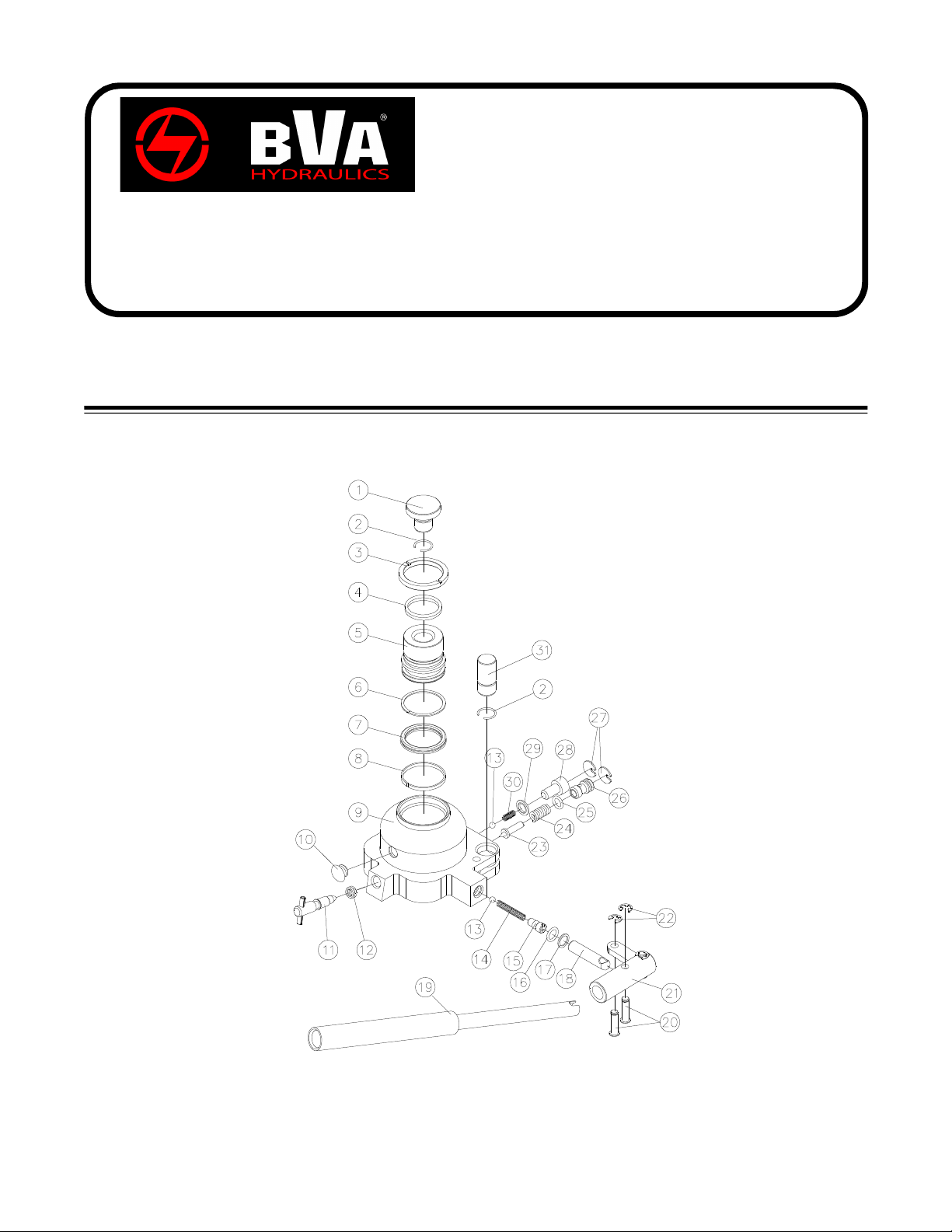
PRODUCT DESCRIPTION
This roduct is designed to lift, osition, or move, but not
sustain, rated ca acity loads. It is not designed to be used
as a stand-alone device. Any load lifted, ositioned, or
otherwise moved by this device, must immediately be
su orted by a ro riately rated mechanical means. A wide
variety of a lications exist for this category of roduct.
S ecial skill, knowledge and training may be required for a
s ecific task and this roduct may not be suitable for all
jobs listed. Unsuitable a lications include a lications that
call for a device to lift, osition, move or su ort ersons,
animals, hazardous materials, mobile homes and
dwellings in general, mirrors, late glass or to connect/
secure hatches, com onents, and materials between
bulkheads. The user ultimately must make the decision
regarding suitability of the roduct for any given task and
therefore acce t res onsibility for that decision.
HYDRAULIC JACK TECHNICAL
SPECIFICATIONS
Rated Ca acity of J11050, J11055: 10,000 lb. (5 ton)
Rated Ca acity of J11100: 20,000 lb. (10 ton)
Rated Ca acity of J11200: 40,000 lb. (20 ton)
Brand name: BVA
Hydraulic Pressure @ Rated Ca acity:
J11050, J11055: 7,000 si
J11100: 7,850 si
J11200: 10,800 si
2
BEFORE USE
Before using this jack, ensure that the intended load
contact oint is able to withstand the load a lied by this jack.
1. Before using this roduct, read the owner’s manual
com letely and familiarize yourself thoroughly with the
roduct, its com onents, and recognize the hazards
associated with its use.
2. To familiarize yourself with basic o eration, use the
o erating handle to engage and turn the release valve:
a. Clockwise until firm resistance is felt to further thread
engagement. This is the ‘CLOSED’ release valve
osition used to ressurize the hydraulic fluid and
raise the ram lunger.
b. Counter-clockwise, but no more than 1/2 turn from the
closed osition. This is the ‘OPEN’ release valve osition
used to lower the ram lunger.
3. Check that the um o erates smoothly before utting into
service. Re lace damaged or missing arts with factory
authorized re lacement arts only. Re air of this roduct
may require s ecial skills and knowledge and should only
be attem ted by a factory authorized service center. Contact
the manufacturer or distributor of this roduct for a list of
factory authorized service centers. Lubricate as instructed
in Maintenance Section.
Bleeding/ Venting Trapped Air
With the release valve in the OPEN osition (2b above) and
with saddle fully lowered, locate and remove the oil filler lug.
Insert the handle into the handle sleeve; then um 6 to 8 full
strokes. This will hel release any ressurized air which may
be tra ed within the reservoir. Oil level should be even with
the bottom of the oil filler lug hole. Reinstall the oil filler lug.
Use of this device may require special skills and
knowledge. Read, understand, and follow all printed materials
provided with and on this device before use.
!
To a oid personal injury and/or property damage:
• Read, understand and follow all rinted materials
rovided with and on this jack.
• This is a lifting de ice only! Ne er work on, under, or
around a load su orted only by a hydraulic jack.
• Immediately su ort the lifted load with a ro riately
rated mechanical means.
• Use only on hard, level surfaces ca able of
sustaining rated ca acity loads.
• Center load on saddle.
• No alteration shall be made to this device. Use only
attachments, ada ters and accessories rovided by
the manufacturer.
• Be alert and sober when using this roduct! Ne er
o erate this equi ment when under the influence of
drugs or alcohol.
• Use only high grade hydraulic jack oil in this roduct.
• Always use a calibrated means of determining how
much force is being a lied by this roduct. Never
exceed the rated ca acity of the jack.
WARNING
!
!

3
SPECIFICATIONS
MAINTENANCE
Important: Use only good grade hydraulic jack oil. Avoid
mixing different ty es of fluid and NEVER use brake fluid,
turbine oil, transmission fluid, motor oil or glycerin. Im ro er
fluid can cause remature failure of the jack and the otential
for sudden and immediate loss of load. We recommend
Mobil DTE13M or equivalent.
Adding
1. With saddle fully lowered set jack in its u right, level
osition. Locate and remove oil filler lug.
2. Fill with oil even with the bottom of the oil filler hole.
Reinstall the oil filler lug.
Changing oil
For best erformance and longest life, re lace the com lete
fluid su ly at least once er year.
1. With saddle fully lowered set jack in its u right, level
osition. Locate and remove oil filler lug.
2. Lay the jack on its side and drain the fluid into a suitable
container.
Note: Dis ose of hydraulic fluid in accordance with local
regulations.
3. Fill with oil even with the bottom of the oil filler hole. Reinstall
the oil filler lug.
Lubrication
A eriodic coating of light lubricating oil to ivot oints will
hel to ensure that um iston linkages move freely.
Note: Never a ly oil to saddle.
Cleaning
Periodically check the um iston and ram lunger, and
saddle for signs of rust or corrosion. Clean as needed and
wi e with a clean, oil soaked rag.
Note: Never use sand a er or abrasive material on these
surfaces !
Storage
Store the jack with um iston, ram lunger/saddle
fully
lowered and release valve o en, but never more than 1/2
turn. This will hel revent rust and corrosion to those critical
surfaces.
Figure 1 - Ty ical Mini Jack Com onents (J11050 shown)
Handle Assembly
Handle Sleeve
Saddle
Oil Filler Plug
Release Valve
Saddle Ada ter
(for J11050 &
J11055 only)
OPERATION
Use of this device may require special skills and
knowledge. Read, understand, and follow all printed
materials provided with and on this device before use.
Raising the Ram Plunger
1. Locate and close release valve by turning handle
clockwise until firm resistance is felt to further thread
engagement.
2. Pum until load reaches desired height.
Immediately
secure with a ro riately rated mechanical devices. It is
recommended you follow the load with cribbing and
blocking where ractical.
Never allow personnel to work or pass under a load
until the load is secured by cribbing, blocking, or other
mechanical means.
Lowering
Make certain that all personnel are clear of the load
before lowering. Control the rate of descent of the load at all
times. The more you open the release valve, the faster the
load descends.
1. Use the manufacturer's rovided o erating handle to
engage and slowly turn the release valve counter-
clockwise, but no more than 1/2 turn.
f the operating handle is damaged, operates
abnormally, or will not positively engage the release valve,
immediately discontinue use of the jack until a
manufacturer's replacement handle assembly can be
acquired.
2. Push ram down and handle sleeve in to reduce ex osure
to rust and contamination after removing jack from under
load.
Model
Ca acity
(ton)
Min. Height
(in)
Max. Height
(in)
Base Size
(L x W)
Weight
(lb.)
J11050 5 2 3/8 3 1/8 4 1/8" x 4" 4.6
J11055 5 3 3/8 4 7/8 4 1/8" x 4" 5.3
J11100 10 4 3/4 6 1/4 4 7/8 x 4 3/8 12.6
J11200 20 5 1/8 6 3/4 5 3/8 x 4 3/4 16.7
!
!
!
!
Ram Plunger

4
Mini Jacks
Ser ice Parts
SFA Com anies 10939 N. Pomona Ave. Kansas City, MO 64153
Tel: 888-332-6419 * Fax: 816-891-6599
E-mail: sales@bvahydraulics.com Website: www.bvahydraulics.com
MODELS: J11050 & J11055
Parts Illustration
J11050-M0
rev 08/07
Note:
Not all com onents of the jack are re lacement items, but are illustrated as a
convenient reference of location and osition in the assembly sequence.
(refer to
page 5
for arts list)
Note: To insure safe and reliable erformance, re lace worn or damaged arts with BVA
Hydraulics authorized re lacement arts only.

Item Model J11050 Model J11055 Description Qty.
1 115-6-1103-104 115-6-1103-104 Saddle 1
2 115-6-1110-101 115-6-1110-101 Retaining Ring 2
3 115-6-1810-109 115-6-1810-109 U er Bearing 1
4 580-7-0270-101 580-7-0270-101 Dust Seal 1
5 N/A N/A Ram Plunger 1
6 * * Back-u Ring 1
7 * * U-cu 1
8 599-7-0360-002 599-7-0360-002 S ecial Washer 1
9 N/A N/A Base Assy. 1
10 505-9-0092-207 505-9-0092-207 Oil Filler Plug 1
11 115-3-1700-104 115-3-1700-104 Release Valve 1
12 * * Oil Seal 1
13 601-7-0006-005 601-7-0006-005 Steel Ball 2
14 511-2-0052-001 511-2-0052-001 S ring 1
15 115-6-1603-104 115-6-1603-104 Screw 1
16 * * O-ring 1
17 * * Back-u Ring 1
18 115-6-1306-108 115-6-1306-108 Pum Piston 1
19 115-4-2100-101 115-4-2100-101 Handle 1
20 518-4-0060-102 518-4-0060-102 Pin 2
21 115-4-1300-104 115-4-1300-104 Handle Sleeve 1
22 677-5-0050-105 677-5-0050-105 “E” Cli 2
23 414-6-1216-107 414-6-1216-107 Needle 1
24 512-2-0067-010 512-2-0067-010 Safety S ring 1
25 * * O-ring 1
26 414-6-1215-307 414-6-1215-307 Safety Valve Screw 1
27 509-9-0145-109 509-9-0145-109 Safety Valve Ca 2
28 649-1-0080-027 649-1-0080-027 Socket Head Bolt 1
29 * * Gasket 1
30 511-2-0048-000 511-2-0048-000 S ring 1
31 115-6-1104-106 115-6-1104-106 Saddle Ada ter 1
(*) 115-3-9901-104 115-3-9901-104 Seal Kit -
5
(*) - Indicates items included in, and available only as art of Seal Kit.
N/A - Part is not available as re lacement.
Mini Jacks
Ser ice Parts
SFA Com anies 10939 N. Pomona Ave. Kansas City, MO 64153
Tel: 888-332-6419 * Fax: 816-891-6599
E-mail: sales@bvahydraulics.com Website: www.bvahydraulics.com
MODELS: J11050 & J11055
Parts List
J11050-M0
rev 08/07
Note:
Not all com onents of the jack are re lacement items, but are illustrated as a
convenient reference of location and osition in the assembly sequence.

6
(refer to
page 7
for arts list)
Note: To insure safe and reliable erformance, re lace worn or damaged arts with BVA
Hydraulics authorized re lacement arts only.
Mini Jacks
Ser ice Parts
SFA Com anies 10939 N. Pomona Ave. Kansas City, MO 64153
Tel: 888-332-6419 * Fax: 816-891-6599
E-mail: sales@bvahydraulics.com Website: www.bvahydraulics.com
MODELS: J11100 & J11200
Parts Illustration
J11050-M0
rev 08/07
Note:
Not all com onents of the jack are re lacement items, but are illustrated as a
convenient reference of location and osition in the assembly sequence.

Item Model J11100 Model J11200 Description Qty.
1 125-6-1103-102 135-6-1103-100 Saddle 1
2 A24-6-4302-107 430-6-4302-406 Retaining Ring 1
3 125-6-1808-100 226-6-1808-106 Retaining Ring 1
4 * * O-ring 1
5 125-6-1204-108 135-6-1204-106 Dust Seal 1
6 * * O-ring 1
7 N/A N/A Ram Plunger 1
8 125-6-1209-108 135-6-1209-106 Ram Bearing 1
9 * * Back-u Ring 1
10 * * U-cu 1
11 N/A N/A Base Assy. 1
12 505-9-0092-207 505-9-0092-207 Oil Filler Plug 1
13 238-6-1701-403 238-6-1701-403 Release Valve 1
14 * * Oil Seal 1
15 511-2-0052-001 512-2-0052-008 S ring 1
16 115-6-1603-104 115-6-1603-104 Screw 1
17 * * O-ring 1
18 * * Back-u Ring 1
19 125-6-1306-106 125-6-1306-106 Pum Piston 1
20 518-4-0080-016 518-4-0080-016 Pin 2
21 125-4-1300-102 125-4-1300-102 Handle Sleeve 1
22 677-5-0070-101 677-5-0070-101 “E” Cli 2
23 125-4-2100-109 135-4-2100-107 Handle 1
24 601-7-0006-005 601-7-0006-005 Steel Ball 2
25 511-2-0048-000 511-2-0048-000 S ring 1
26 * * Gasket 1
27 649-1-0080-027 649-1-0080-027 Socket Head Bolt 1
28 509-9-0145-109 509-9-0145-109 Safety Valve Ca 2
29 414-6-1215-307 414-6-1215-307 Safety Valve Screw 1
30 * * O-ring 1
31 512-2-0067-010 512-2-0067-010 S ring 1
32 414-6-1216-107 414-6-1216-107 Needle 1
(*) 125-3-9901-102 135-3-9901-100 Re air Kit -
7
(*) - Indicates items included in, and available only as art of Seal Kit.
N/A - Part is not available as re lacement.
Mini Jacks
Ser ice Parts
SFA Com anies 10939 N. Pomona Ave. Kansas City, MO 64153
Tel: 888-332-6419 * Fax: 816-891-6599
E-mail: sales@bvahydraulics.com Website: www.bvahydraulics.com
MODELS: J11100 &J11200
Parts List
J11050-M0
rev 08/07
Note:
Not all com onents of the jack are re lacement items, but are illustrated as a
convenient reference of location and osition in the assembly sequence.

8
Possible Causes Correcti e Action
Jack will not ressurize
Jack *bleeds off after lift
* 'bleeds off' means load slowly and
unintentionally lowers after lifting
While lowering, fluid leaks from
reservoir area
Jack saddle will not descend to
lowest advertised height
Ram lunger will not remain
lowered after released from contact
with load (cree s back u )
Poor lift erformance
Will not lift to full extension
• Release valve not tightly closed
• Load is too heavy
• Hydraulic unit malfunction
• Reservoir overfilled
• Ram lunger/cylinder deformed,
seized u in ram cylinder and/or
to nut, likely the result of off-
center loading
• Air tra ed in system
• Fluid level low
• Air tra ed in system
• Hydraulic unit malfunction
• Fluid level low
• Ensure release valve tightly closed
• Consider higher ca acity jack
• Contact Service Center
• Drain fluid to ro er level
• Contact Service Center
• Follow the Owners Manual instructions
for bleeding air from system.
• Ensure ro er fluid level
• Follow the Owners Manual instructions
for bleeding air from system.
• Contact Service Center
• Ensure ro er fluid level
TROUBLESHOOTING
Symptom
LIMITED LIFETIME WARRANTY
BVA Hydraulics®, re resented in the United States by SFA Com anies [“SFA”] warrants this roduct to be free from defects in
material and workmanshi for the life of the roduct as long as the original urchaser owns the roduct. The warranty is non-
transferable and is subject to the terms, exclusions, and limitations described below:
• Damaged com onents, including but not limited to bent rams, dented or crushed cylinder walls, broken welds or cou lers
as well as worn out seals, o-rings and s rings are the result of misuse and not covered by warranty and BVA Hydraulics
will not rovide any warranty credit for such damaged com onents.
• This warranty does not cover ordinary wear and tear, overloading, alterations (including re airs or attem ted re airs not
erformed by BVA Hydraulics or one of its authorized ersonnel), im ro er fluid use, or use of the roduct in any manner
for which the roduct was not intended or the use of which is not in accordance with the instructions or warnings rovided
with the roduct.
• In the unlikely event that a BVA Hydraulics roduct fails due to material defect in workmanshi , you may contact SFA for
dis osition. In such cases, the customer’s sole and exclusive remedy for any breach or alleged breach of warranty is
limited to the re air or re lacement of the defective roduct.
• Under no circumstances is BVA Hydraulics liable for any consequential or incidental damage or loss whatsoever.
• THIS WARRANTY IS LIMITED TO NEW PRODUCTS SOLD THROUGH AUTHORIZED DISTRIBUTORS AND OTHER
CHANNELS DESIGNATED BY BVA HYDRAULICS. NO AGENT, EMPLOYEE OR OTHER REPRESENTATIVE OF BVA
HYDRAULICS IS AUTHORIZED TO MODIFY THIS WARRANTY.
• THE FOREGOING IS EXCLUSIVE AND IS IN LIEU OF ALL OTHER EXPRESS AND IMPLIED WARRANTIES, INCLUDING
BUT NOT LIMITED TO THE IMPLIED WARRANTIES OF MERCHANTABILITY AND FOR A FITNESS FOR A PARTICULAR
PURPOSE.
• Com onents not manufactured by BVA Hydraulics including certain motor systems, gasoline engines, and others are not
covered by this warranty and instead are covered by the manufacturer’s se arate manufacturer’s warranty rovided in the
ackage.
• BVA Hydraulics’ liability in all cases is limited to, and will not exceed the urchase rice aid for the roduct.
SFA Com anies
10939 N. Pomona Ave. Kansas City, MO 64153
Tel: 888-332-6419
E-mail: sales@bvahydraulics.com
This manual suits for next models
3
Table of contents
Other BVA Hydraulics Jack manuals
Popular Jack manuals by other brands

Powerbuilt
Powerbuilt 640912 Operating and maintenance instruction manual

ULTIMATE SPEED
ULTIMATE SPEED URW 2 A1 HYDRAULIC TROLLEY JACK operating instructions

Daytona
Daytona DTJ10T Owner's manual & safety instructions

Clarke
Clarke CTJ2000G manual

Cartrend
Cartrend 10005 Original operating instructions

Tardis
Tardis 20-200-01 installation instructions

Daytona
Daytona DS400S Owner's manual & safety instructions

MAC TOOLS
MAC TOOLS JSA300AJ owner's manual

GÜDE
GÜDE GRH 2/330 I Translation of the original instructions

Blue point
Blue point MagicLift YA642C Operating instructions & parts manual

Torin
Torin BIG RED T82253 owner's manual

WilTec
WilTec 51296 Operation manual