3
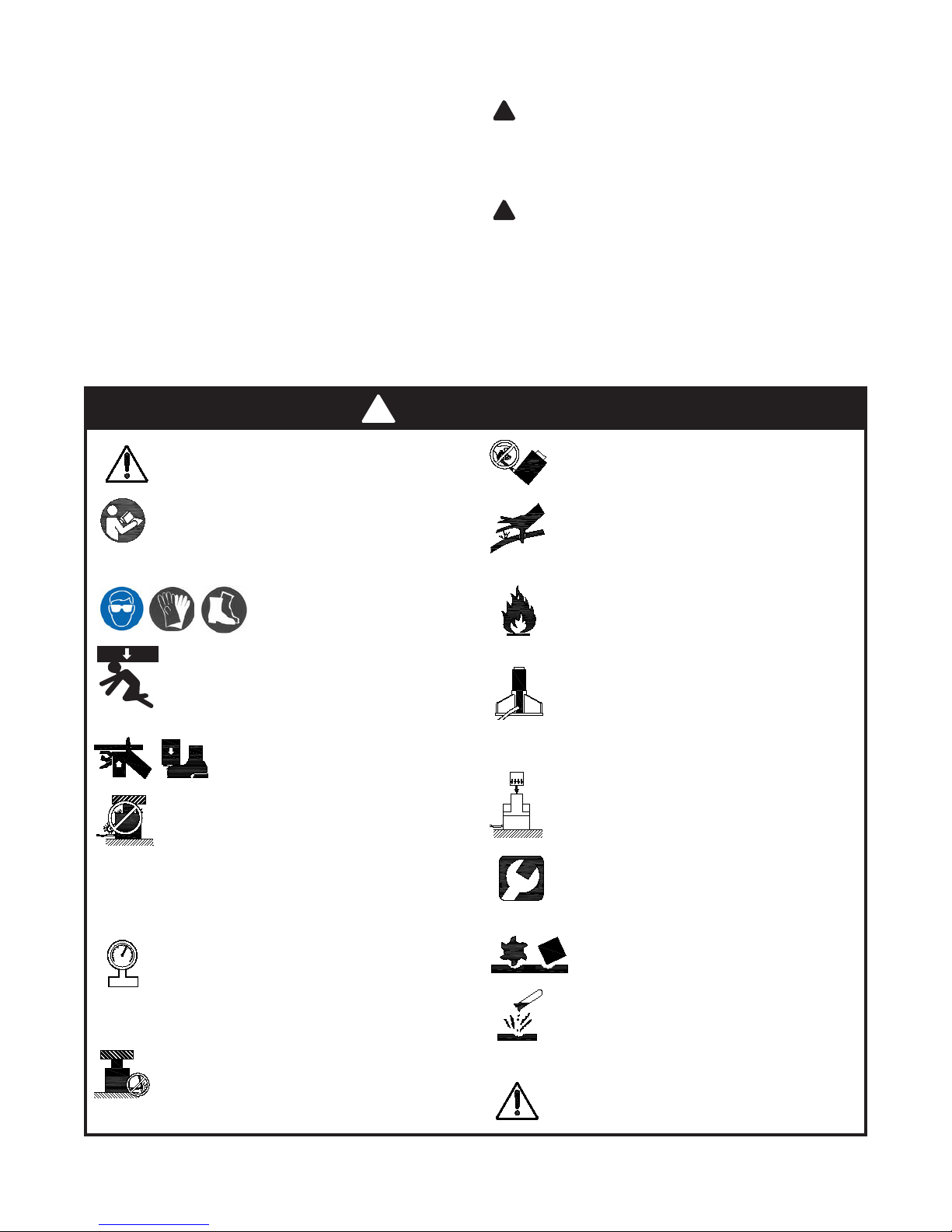
Failure to comply with the following warnings
may
result in personal injury as well as
property damage.
•
Study, understand, and follow all instructions
provided with and on this device before use.
• The user must be a qualied operator familiar
with the correct operation, maintenance, and use of
cylinders.
Wear protective gear when
operating hydraulic equipment.
This device is NOT suitable for use as support
device! As the load is lifted, use blocking and
cribbing to guard against a falling load.
Stay
clear of a lifted load before it is properly
supported
.
Never rely on hydraulic pressure to support a load.
Crush Hazard. Keep hands and feet
away from cylinder and workpiece
during operation.
•
Do not exceed rated capacity of the cylinder or
any equipment in the system. The cylinder is
designed for a max. pressure of 10,000 psi.
•
Do not connect a cylinder to a pump with higher
pressure rating.
• Do not subject cylinder to a shock loads, a load
dropped suddenly, causing the system pressure to
exceed rated pressure.
The system operating pressure must not exceed
the pressure rating of the lowest rated component
the system. Install a pressure gauge or other load
measuring instrument to monitor the operating pressure. Burst
hazard exists if hose, connection or any other component in
the system exceed its rated pressure.
Avoid damaging hydraulic hose. Do not allow
hose to kink, twist, curl, crush, cut or bend so
tightly that uid ow within the hose is blocked or
reduced. Periodically inspect the hose for wear.
Do not pull, position or move cylinder setup by
the hose. Use carrying handle or other means
of safe transport.
Do not handle pressurized hoses. Never attempt
to grasp a leaking pressurized hose. Ensure to
release the system pressure before disconnecting
hydraulic hose or connections.
Hydraulic uid can ignite and burn. Keep
hydraulic equipment away from ames and
heat.
Excessive heat will soften seals, resulting in
uid leaks. Heat also weakens hose materials.
Cylinder must be on a stable base which is able
to support the load while pushing or lifting. Use
shims, friction material or constrains to prevent
slippage of the base or load. Ensure cylinder is fully engaged
into/onto adapters, extension accessories.
Center load on cylinder. Distribute load evenly
across the entire saddle surface. Do not
o-center loads on a cylinder. The load can tip
or the cylinder can “kick out”.
Never try to disassemble a hydraulic cylinder,
refer repairs to qualied, authorized personal.
Contact BVA Hydraulics tech service for authorized
service center.
Do not subject hose to sharp objects or
heavy impact.
Hose material or seals must not come in
contact with corrosive materials such as
battery acid, creosote-impregnated objects
and wet paint. Never paint a coupler or hose.
•
No alteration shall be made to the cylinder.
•
Use only factory authorized fasteners,
accessories and hydraulic uid.
Heavy
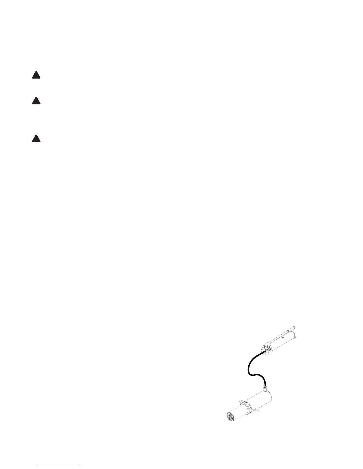
INSTALLATION
NOTICE: Use an approved, high-grade pipe sealant to seal
all hydraulic connections.
1.
Remove the dust cover and rubber plug from coupler
.
2. Inspect all threads and ttings for signs of wear or damage,
and replace as needed. Clean all threads and ttings.
3. Connect hydraulic hose from hydraulic pump to the cylinder
coupler. Ensure that there are no uid leaks.
4. Install in-line pressure gauge.
5. Check for leaks in system and have repaired by qualied
personnel.
NOTICE: The use of cylinder attachments or extensions
reduces the cylinder capacity by at least 50% per attachment/
extension.
WARNING: Before operating the pump, tighten all
hose connections with proper tools. Do not overtighten.
Connections should only be tightened securely and leak-
free. Overtightening can cause premature thread failure
or high pressure ttings to burst.
WARNING: Before repairs are made, depressurize
cylinder.
Tips for hydraulic hoses & uid transmission lines:
• Avoid short runs of straight line tubing. Straight line runs
do not provide for expansion and contraction due to
pressure and/or temperature changes.
• Reduce stress in tube lines. Long tubing runs should be
supported by brackets or clips.
!
!
WARNING
!