BYOU BEAUTY Operating instructions

L8543185 ENG 03/2016 rev 0
Complete kit for the automation of swinging gates
Instructions and Recommendations for installation and use
MADE IN ITALY
BEAUTY

2
Index
General recommendations .....................................................................3
Product description ................................................................................3
Content of the kit....................................................................................4
Description of the automation ................................................................4
Preliminary checks.................................................................................5
Technical Data, dimensions and limits of use ........................................5
Electric connections ...............................................................................6
Tools and materials ................................................................................7
Choice of installation measurements - 1................................................7
Choice of installation measurements - 2................................................8
Adjustable brackets BTY.1 ......................................................................8
Fixing the gear motor brackets BTY.1.....................................................9
Fixing the gear motor brackets BTY.2...................................................10
Regulation of mechanical opening and closing stops ..........................11
Gear motors wiring...............................................................................11
Fixing the CP.BTY control unit...............................................................11
Installation of the flashing light F.BY ..................................................12
Installation of photocells P.BY...............................................................13
Installation of selector K.BY..................................................................14
Small columns C.BY..............................................................................15
Transmitter BY ......................................................................................15
Control unit CP.BTY connections...........................................................16
Self-regulation of the functioning parameters (AUTO)..........................17
Programming the CP.JMP control unit - Introduction ...........................17
Regulation of the motor thrust (PMOT) .................................................18
Regulation of the automatic closure time (TCA) ..................................18
Step-by-Step functioning mode (PP) ....................................................19
Pre-flashing functioning mode (Pre).....................................................19
Regulation of the phase shift time when closing (TDMC).....................19
Condominium function (IBL) .................................................................20
Selection of the opening/closure speed (Sld).......................................20
Resetting the control unit (Res) ............................................................20
Memorising new transmitters (RADI>PP).............................................21
Memorising pedestrian function (RADI>Ped) .......................................21
Deleting transmitters (RADI>CLR) ........................................................22
Complete deletion of the receiver memory (RADI>RTR).......................22
Remote controls quick duplication .......................................................22
Inspection and commissioning.............................................................23
What to do if... ......................................................................................24
User guide ............................................................................................25
Dear Customer
We would like to congratulate and thank you for choosing the
BYOU systems.
BEAUTY like all other products in the range it is the fruit of
careful and accurate choice of materials and components. The
result is a product that interprets and embodies captivating
designs and state-of-the-art technolog.
BYOU products are covered by a warranty with duration of
2 years.
BYOU is not liable for damage caused by improper use or by
incorrect installation of products or components.
The descriptions and illustrations in this manual may be subject
to modification at any time by the manufacturer, who reserves
the right to make updates to the product of a technical, con-
struction or commercial type, without having to update this
publication within specific times.
For any information of a technical or commercial manner,
contact:
BYOU è un marchio di
AUTOMATISMI BENINCÀ SpA
via Capitello, 45
36066 Sandrigo (VI) ITALY
Tel +39 0444 1510294
Fax +39 0444 759728
info@byouweb.com
www.byouweb.com

3
General recommendations
WARNING: Important safety instructions. Follow all
instructions since incorrect installation can lead to
severe injury.
f this is the first time you realise an automation for swing
gates with Beauty, we recommend that you read this manual
carefully as it contains important advice and information for
the realisation of the plant in safe conditions.
Keep the various components on hand to gain confidence
with them while reading this manual.
Keep this manual for future use.
BEAUTY is realised in a way to allow easy installation and
configuration of the system, however, some phases require
the presence of qualified staff.
When reading this manual pay particular attention to these
symbols:
Authorised technician.
Indicates the phases to be performed in the pres-
ence of mains voltage. The presence of qualified
staff is required (electrician or authorised installer),
in complete respect with the Safety Standards in
force.
Attention!
Potentially dangerous operations. Scrupulously
respect the indications given.
Useful indication.
Suggestions and recommendations for simplifying
and/or improving the installation operations.
The automation of a door cannot be considered the only
device for protection against intrusion.
Do not use any of the components in unsuitable environ-
ments (salty, acid or potentially explosive atmosphere)
All operations that require the protection shells of the
devices opened, must take place without mains power
supply.
This item is not intended to be used by people (including
children) with reduced physical, sensorial or mental abili-
ties, or without adequate knowledge of the product, unless
they are under the supervision of eligible persons or they
have received instructions for use by people in charge of
their security.
Check that the temperature range marked on the drive is
suitable for the location.
The drive cannot be used with a driven part incorporating a
wicket door (unless the drive cannot be operated with the
wicket door open).
Ensure that entrapment between the driven part and the
surrounding fixed parts due to the opening movement of
the driven part is avoided.
After installation, ensure that the mechanism is properly
adjusted and that the protection system and any manual
release function correctly.
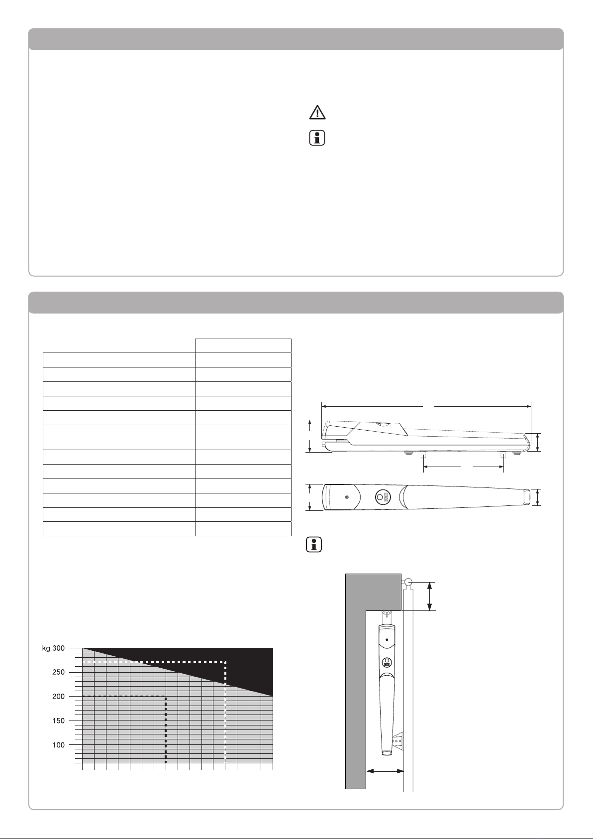
DESTINATION OF USE
This product is destined exclusively for the opening and
closure of swing doors for the passage of vehicles, charac-
terised by dimensional limits and weight as indicated in this
manual in the “Limits of use” paragraph.
No other use is allowed.
BYOU is not liable for uses that are not in compliance with
those indicated in these instructions.
The kit is made up from two electromechanical operators
with 24V direct current motor, which allows movement of
the leaves via a worm screw.
The control unit commands the movement of the two motors
and the functioning of the various accessories.
The supplied accessories are:
- 1 P.BY pair of photocells: they interrupt the movement of
the leaf if there are obstacles present.
- 1 F.BY flashing light: flashing light that indicates that the
door is moving.
- 1 K.BY key selector switch: installed externally, allows the
opening and closure by means of a customised key.
- 2 BY radio transmitters: remote control for opening/clos-
ing the door.
Other accessories available as options:
- CB.BY emergency battery kit: in case of a power cut, it
allows the functioning of the leaf by batteries and relative
battery charger installed inside the operator.
- C.BY pair of small columns for additional pair of photo-
cells F.BY: to be installed within the property (see para-
graph C.BY).
Product description

4
Content of the kit
1 BEAUTY: Pair of electromechanical operators.
2BTY.1: Pair of pillar fixing brackets with screws and
bolts.
3BTY.2: Pair leaf fixing brackets with screws and bolts.
4 CP.BTY: Control unit with plugs and screws.
5 K.BY: Key selector.
6 BY: Pair of 4-channel radio transmitter.
7 P.BY: Pair of photocells for wall installation
1 transmitter( “TX”)
1 receiver (“RX”)
8 BTY.3: Release keys for manual manoeuvre
9Plugs and screws for fixing the accessories (flashing
light, key selector, photocells)
10 F.BY: Flashing light with built-in aerial
Note: The content of the package may undergo variations. If
in doubt, consult your local dealer.
1
Description of the automation
With reference to the list of components in fig. 1, fig. 2 shows a typical plant that can be realised using BEAUTY.
1 4
6
33
6
5
10
22
Fig.1
Fig.2
A
2 3
4
5
6
7 10
8
9
1

5
Preliminary checks
It is indispensable to carry out several checks before starting
installation:
• Try and open the gate manually, the leaves must move
without effort and without points of resistance for the entire
run.
• When left in any intermediate position the leaf must not
move.
• The hinges and components subject to wear must be in
perfect working condition. If this is not the case, replace
the faulty parts.
• The door structure must be strong and the leaves rigid.
• With the gate completely closed, check that the leaves are
aligned perfectly along their entire length.
• The electric set-ups necessary for installation are highlighted
in the “Electric connections” paragraph. If they are not pre-
existing they must be realised, with the aid of a specialised
technician, if necessary (electrician).
• The pillars supporting the leaves must be suitable for fixing
the gear motors.
• Beauty has adjustable mechanical stops both in
opening and closing. However, a stop for closure on
the ground is recommended (Fig.2-ref.A).
The reliability and safety of the automation depend
on the state of the gate structure.
Check that there is enough space for installation of the
operator in safe and comfortable conditions.
Technical Data, dimensions and limits of use
TECHNICAL DATA
BEAUTY
Control unit power supply 230 Vac
Motor power supply 24Vdc
Absorbed power 80 W
Maximum current absorbed 3,5 A
Maximum thrust 1500 N
Maximum frequency of use
(complete opening/closure cycles)
15 cycles/hour
80 cycles/day
Protection rating IP44
Functioning temperature -20°C / +70°C
Opening time (90°) 12/18 s
Run 300 mm
Noise <70 dB
Weight 4,2 kg
LIMITS OF USE
Table 1 indicates the maximum values in the grey area (weight
by leaf length) acceptable for the BEAUTY automation
For example:
200 kg and 1.55 m leaf
It lies within the limits of use (black dotted line)
270 kg and 1.80 m leaf:
It DOES NOT lie within the limits of use (white dotted line)
2,0m1,91,81,71,61,51,41,31,2
DIMENSIONS
Fig.3 indicates the main overall dimensions.
The measurements are expressed in millimetres.
The 300 mm measurement represents the maximum run that
the rod can make during movement.
715
300
min 150
60
max 150
52
105
89
Fig.3
Check, with the leaf completely open, that there is suf-
ficient space for installation (Fig. 4).
Fig.4
Tab. 1
715
300
min 150
60
max 150
52
105
89

6
Electric connections
The cables necessary for the installation of BEAUTY can vary according to the accessories installed.
No connection cable is supplied.
Fig. 5 indicates the cables for standard installation.
List of cables
Connection Type Maximum length and notes
A Mains power supply to the control unit 3x1,5mm230m - [1]
B Motor connection 2x1,5mm215m - [2]
C Photocell transmitter connection 2x0,5mm220m - [3]
D Photocell receiver connection 4x0,5mm220m - [3]
E Key selector connection for external command 4x0,5mm220m
F Flashing signal light connection 2x1,0mm210m
G Connection of the aerial built-in the flashing light RG 58 [4]
Notes
[1]
A pre-wired cable with plug is supplied that is to be used exclusively for installation tests and cannot
be used for the continuous use of the automation.
A qualified BYOU technician will replace it with a network connection that is in compliance with the
Standards in force.
An omnipolar switch should be provided with the contact opening of at least 3 mm, provided with
overload protection and able to cut off the system from the mains.
Means for disconnections must be incorporated in the fixed wiring in accordance with the wiring
rules.
[2] It is recommended not to exceed 15 m in length. If it is indispensable to exceed this limit, increase the section of the cable.
[3]
As the receiver photocell (labelled RX) requires more cables with respect to the transmitter photocell (labelled TX), it is
more practical to installed the receiver on the wall nearest to the control unit, while the transmitter can be positioned
on the wall furthest away.
[4] There is an aerial pre-installed in the control unit, which in most cases makes this connection superfluous. If reception is
disturbed, the capacity of the receiver can be improved by connecting the aerial in the flashing light to the control unit.
As in layout Fig.5, the connections B and C must be underground: for this purpose prepare a suitable connection race-
way that is sufficiently resistant for the type of use.
If the other connections are not already set-up, they will be realised in a bricked-up raceway or using raceways from
the outside (flexible corrugated sheath) that is in compliance with the Standards in force.
If in doubt, contact staff that is specialised in the realisation of these set-ups.
The cables used must be suitable for the type of connection. For example, for connection protected by race-
ways use H03VV-F cables, for cables in the outdoor environment always use the H07RN-F type.
A
E
G
F
B
C
D
Fig.5
B

7
Tools and materials
#6
Make sure that there are all tools and materials necessary
for installation (fig.6). Also check that they are in compliance
with Standards and in perfect working order.
Use suitable individual protection devices I.P.D. (gog-
gles, gloves, etc)
The length and type of connection cables depend on
the accessories installed (see “Electric connections”
paragraph).
The fixing devices for the gear motor are not supplied
as they depend on the features of the materials used
for the pillars and the leaves.
Choice of installation measurements - 1
Fig.6
Fig.7
Fig. 7 represents a view from above of the automation, indicating
the most important measurements for installation.
R indicates the hole in bracket BTY.1 onto which the gear mo-
tor is fixed and corresponds to the rotation axes of the gear
motor. It is necessary to calculate the correct positioning as
indicated below.
M: is a measurement on the gate and represents the distance
between the gate rotation axis and gear motor fixing surface
S: a distance that can be adjusted by means of the supplied
bracket BTY.1.
Y: is given by the sum of M+S.
X: depends on the opening angle requested and by the value
of the Y measurement.
IMPORTANT: The values of the X and Y measure-
ments must be as similar as possible (max difference
50 mm).
Values that are too different to each other do not allow regular
movement of the leaves and could cause malfunctioning.
Detect the value of the measurement M precisely and state it
in every box in column M in Table 1.
Calculate all values possible of the Y measurement, adding the
value M to the various values of the column S, completing all
boxes in column Y of table 1.
Tab. 1
S + M = Y
40 mm ......... mm ......... mm
97 mm ......... mm ......... mm
117 mm ......... mm ......... mm
121 mm ......... mm ......... mm
135 mm ......... mm ......... mm
155 mm ......... mm ......... mm
Establish the opening angle of the leaf:
- Take the leaf into the completely open position.
- If the angle of opening exceeds 90° find the appropriate angle
using, if necessary, the goniometer printed on the last page of
this manual.
Below find three tables, each referring to one of the opening an-
gles possible, up to 90°, from 90° to 100°, from 100° to 110°.
Up to 90° from 90° to 100° from 100° to 110°
Y X Y X Y X
100 mm 150 mm 100 mm 140 mm 100 mm 140 mm
110 mm 150 mm 110 mm 140 mm 110 mm 130 mm
120 mm 150 mm 120 mm 140 mm 120 mm 130 mm
130 mm 140 mm 130 mm 130 mm
140 mm 140 mm 140 mm 120 mm
150 mm 130 mm 150 mm 120 mm
160 mm 120 mm
170 mm 120 mm recommended
mesaurement
Depending on the values calculated in the Y column of Table 1,
select the pairs of measurements Y and X as similar as possible
in the table with the requested opening angle.
Make note of the measurement S corresponding to measure-
ment Y thus obtained. This value is indispensable for the correct
regulation of the bracket BTY.1, described in the “Fixing the
gear motor brackets BTY.1” paragraph.

8
Fig.8
Choice of installation measurements - 2
As an example, let’s suppose that the measurement M detected
on the leaf is 35 mm.
The value 35 is inserted in the column M and table 1 is com-
pleted, calculating the different values Y:
Tab. 1
S + M = Y
40 mm 35 mm 75 mm
97 mm 35 mm 132 mm
117 mm 35 mm 152 mm
121 mm 35 mm 156 mm
135 mm 35 mm 170 mm
155 mm 35 mm 190 mm
We therefore find the opening angle of the leaf. Let’s suppose
that the angle detected is 95°, the reference table is that for the
angles from 90° to 100°.
from 90° to 100°
Y X
100 mm 140 mm
110 mm 140 mm
120 mm 140 mm
130 mm 130 mm
140 mm 120 mm
150 mm 120 mm
Among the values recommended in this table, note that the
Y:130 measurement is the nearest to the measurement of 132
mm in table 1.
Our installation measurements are:
Y X S
130 mm 130 mm 97 mm
Make note of these values for positioning of the brackets
BTY.1
Adjustable brackets BTY.1
Using the adjustable brackets BTY.1 it is possible to install the
BEAUTY gear reducer with different installation measurements,
without having to make cuts and perform welding.
There are two holes in the bracket, both used to fix the gear
motor.
Figure 8 shows the main positions with relative measurements,
both for hole A and for hole B.
Select the position that corresponds to position “S” calcu-
lated in Table 1 of the “Choice of installation measurements”
paragraph.
The positions 1 and 2 do not modify the value of the X meas-
urement, the fixing gear motor hole corresponds to the central
axis of the bracket.
The positions from 3 to 8 change the value of the X measure-
ment.
With reference to the previously described example, the meas-
urement S of 97 mm requires the position 6.
Note that in this position the measurement X is modified.
It will be necessary to add 72 mm to the measurement X pre-
viously calculated in order to have the new bracket-fixing axis.
A
B

9
Fixing the gear motor brackets BTY.1
The screws for wall fixing are not supplied, they are
selected on the basis of the features of the materials
used for the pillars and leaves.
Assemble the fixing brackets BTY.1 (fig.1-ref.2).
Figure 8 illustrates an example of fixing position 1:
75
75
X
37,537,5
42
P
H
�
Before fixing the brackets it is important to determine their height
from the ground and, consequently, the height of the motor.
1) The measurement H (Fig.10) must be greater than 350 mm.
Installation too near to the ground can cause malfunctioning
due to humidity, dirt, snow, which infiltrate inside the gear
motor.
BTY.1
It is important to consider the correspondence between the height
established and the presence of gate support structures:
Fig.9
Fig.10
Fig.11
C
F
V
D
R
Fig.12
2) The electrical set-up must preferably be under the fixing
bracket (fig. 10 - ref.P).
Identify measurement X on the pillar, mark 4 holes for fixing the
plate BTY.1 with the measurements indicated in figure 10.
Attention: some positions of the bracket BTY.1 require a correc-
tion of the measurement X as indicated in Figure 8
Fix the bracket using the plugs and screws that are suitable for
the type of material (fig. 11).
Apply the gear motor to the bracket (fig.12):
- Loosen screw F and then remove the sump C
- Insert the washer R placing it on the bracket
- Insert the gear motor
- Block the gear motor via the screw V and nut D.

10
Fixing the gear motor brackets BTY.2
The BEAUTY gear motors supplied with the retracted pin of
about 1 cm with respect to the end run stroke (fig. 13).
BTY.2
This is the correct position of the pin for fixing the bracket BTY.2
onto the leaf. Proceed as follows:
- Assemble the bracket BTY.2 as indicated in figure 14
- Apply the bracket BTY.2 to the gear motor pin, blocking it
with screw V, positioning the washers R1 and R2 as indicated
in figure 15.
The smooth washer R1, must be positioned above the
grooved washer R2.
With the leaf in the completely closed position, take the gear
motor with the bracket to rest on the leaf (fig.16):
10 mm
Use a spirit level to check that the gear motor is perfectly
horizontal and then mark the two points for drilling the leaf
(fig. 17).
V
R2
R1
Also in this case the fixing devices will be selected on the basis
of the material with which the leaf is made. Self-threading screws
are used in the example in figure 18.
Release the gear motor by turning the circular cover by 180°
(fig. 19) and then insert the release key and turn it 90°.
The gear motor is now released and the leaf can be opened
and closed manually.
Use several complete manoeuvres to check that the fork slides
regularly along the entire run.
Check that during movement the gear motor does not collide
with the pillar or the leaf. In this case check the positions of
the adjustable brackets. In some cases it may be necessary
to mount the bracket BTY.2 in a way to move the gear motor
away from the leaf (fig.20).
Fig.13
Fig.14
Fig.15
Fig.16
Fig.17
Fig.18
Fig.19
Fig.20

11
Regulation of opening and closure mechanical stops
There are two adjustable mechanical stops on the bottom of
the gear motor, one to stop the opening leaf (fig.20 -ref A), one
to stop the closing leaf (fig.20 -ref C).
With the leaf released, take the leaf into the completely closed
position.
Use a 6 mm hex wrench to loosen the mechanical stop C and
take it to rest at the pin.
Take the leaf to the desired opening position.
Loosen the mechanical stop A and take it to rest at the pin.
Using several manual opening and closure manoeuvres, check
that the leaf stop point is correct.
Fig. 20
C
A
Gear motors wiring
The connection cable to the control unit must have a sufficient
curve to follow the movement of the gear motor during the
manoeuvre (fig.21 - ref. A).
Loosen the fairlead P, insert the cable through the gear motor
and then block the fairlead
Make the connections on the clamp as indicated in Fig.22,
respecting the connections indicated in the “Electric connec-
tions” paragraph.
Fig. 21
P
A
Fixing the CP.BTY control unit
With reference to the “Electric connections” chapter - Fig.5,
select the most suitable position for fixing the control unit, in
proximity of the gate in a way to reduce the length of the cables
and in a position protected from any accidental blows.
Remove the 4 screws A (fig.23) and then remove cover B
There are 4 set-ups (C) present on the base of the control unit
container, which must be broken using a screwdriver.
Place the base on the wall and mark the 4 drilling points.
Make the 4 holes and insert the 4 plugs (E), fix the control unit
with the 4 screws D. Plugs and screws are supplied.
There is a seat (F) on the base of the container for the passage
of the connection cables. This must be opened using a screw-
driver in order to fix a fitting for the corrugated pipe.
The control unit has a pre-wired mains power supply cable
that can only be used for installation tests, using an exten-
sion for example. A qualified BYOU technician will replace
it with a network connection that is in compliance with the
Standards in force.
Fig. 22
A
C
B
D
Fig. 23
E
F

12
Installation of the flashing light F.BY
Description
Flashing light signalling that the gate is in movement for auto-
matic doors and gates. It has a built-in aerial for the reception
of radio transmitters.
Installation
Choose the position of the flashing light so that it is proximity
of the gate and easily visible.
The flashing light can be fixed onto a horizontal or vertical
surface. In the case of vertical installation the protection rating
is reduced to X4.
A
Loosen the two screws V and then remove the transparent
cover.
ANT
SHIELD
ANT
SHIELD
ANT
SHIELD
V
V
H
Remove the electronic circuit, pulling the two plastic tabs H
outwards, thus releasing the board.
ANT
SHIELD
Two 6 mm plugs and relative screws are supplied for fixing the
flashing light.
Make two holes with diameter of 6 mm.
Insert the cable and fix the base using the plugs and screws.
ANT
SHIELD
Connections
ANT
SHIELD
Connect the 24V flashing light output of the control unit to the
terminal board M1 (see main connection layout).
Connect the aerial cable RG58 to the terminal board M2 (if
requested). The external shield must be connected to the
B C
Trace the drilling points using the base as a reference. The
central hole must correspond to the passage of the cables.
ANT
SHIELD
SHIELD clamp. The signal cable must be connected to the
ANT clamp.
Put the board back into the relevant sear and then close the
flashing light.
TECHNICAL DATA Flashing light F.BY
Power supply 24Vac Flashing light output
of the BYOU control units
Bulb E14/24Vac/dc
Absorption 600 mA
Functioning temperature -20°C / +70°C
Protection rating IP44
Dimensions 145x65x128 (mm)

13
40÷60 cm
Description
Pair of photocells for detection of obstacles for automations
for doors and gates.
The pair is made up of a transmitter (labelled TX) that
sends and infrared ray towards the receiver (labelled RX).
The receiver has an output with NC contact (normally closed).
The interruption of the ray causes the contact to open, the
control unit detects the receiver switch-over and interrupts the
movement according to the settings selected.
Installation
Open the photocells by using a screwdriver as a lever in the
slot
The difference between the receiver and the transmitter is evi-
dent from the number of clamps present on the boards:
4 clamps for the receiver (RX)
2 clamps for the transmitter (TX)
The two photocells must be fixed on the outside and as near
as possible to the gate:
Trace the drilling holes using the pho-
tocell base as a reference.
The hole in proximity of the terminal
board must correspond to the passage
of the cables.
Four 6 mm plugs and relative screws
are supplied for fixing the photocells.
Make two holes with diam-
eter of 6 mm in a way that
the hole in proximity of the
terminal board corresponds
to the set-up of the cables.
Insert the cable and fix the
base of the photocell to the
wall using the plugs and
screws.
Connections
Connect the TX and RX to the control unit as per the main con-
nection layout.
TX only requires power supply from the 24V output of the control
unit, respect the polarities (+/-).
RX requires 24V power supply (respect the polarities +/-) and
the connection of the NC contact at the PHOT C input.
(TX)(RX)
Installation of photocells P.BY
(RX)(TX)
Make the connections and re-position the covers checking that
the cover with the lens (RX - 4 clamps) is applied to the receiver.
The lens can be recognised by the concentric circles that are
visible in transparency.
4 2
At a height of 40÷60 cm from the ground:
(RX)(TX)
TECHNICAL DATA P.BY photocells
Power supply 24Vac/dc
Capacity
(in optimal conditions) about 20 metres
Absorption 15mA(TX) - 20mA(RX)
Functioning temperature -20°C / +70°C
Protection rating IP44
Dimensions 90x35x31 (mm)

14
Installation of selector K.BY
Description
Key selector with control of automations for automatic gates
and doors.
Wall fixing, customised key.
The customised key also has a burglar-resistance function as
it is indispensable for opening the selector.
Installation
Select the position of the selector in a way that it is in proximity
to the gate, at a height of about 80/100 cm.
To open the selector, remove the screw V, insert the key, turn
it in one of the two directions and hold it in this position, lift the
selector cover, which separates from the fixed base. Keep the
screw V, which is indispensable for closing the selector.
Two 6 mm plugs and relative screws are supplied for fixing the
selector base to the wall.
V
Using the support as a reference, mark and make two holes
with diameter of 6 mm in a way that the lower hole corresponds
to the set-up of the cables.
Insert the cable and fix the base to the wall using the plugs
and screws.
Connections
A terminal board is installed on the selector for the connection
to the Step-by-Step input (PP) of the control unit:
No polarity (+/-) has to be respected.
To close the selector, turn the key and hold it in this position,
insert the selector into the base fixed to the wall.
Release the key and fix the screw V.
TECHNICAL DATA F.BY selector
Contacts
1 micro switch, with spring
for return to central position
Functioning temperature -20°C / +70°C
Protection rating IP44
Dimensions 72x90x46 (mm)
V

15
Small columns C.BY
PHOT C
PHOT
Photocells on small column
The article C.BY is available as an optional accessory, a pair
of small columns measuring 50 cm. for the installation of two
additional photocells P.BY. They must be positioned inside the
property to protect the movement area of the leaves.
Two distinct connections are envisioned in the control unit that
are to be used according to the position of the photocell:
PHOT C: The photocell is only active in the closure phase.
PHOT: The photocell is active in opening and closure.
This functioning mode allows the vehicle to enter even if the
leaf is not completely open, as long as the manoeuvre area is
free from obstacles.
C.BY
Description
Radio transmitter for the long distance commands for BYOU
automations.
Functioning
The transmitter has three buttons through which it is possible to
command the various functions of the automation, configurable
in the control unit.
Replacing the battery
When the signal LED starts to flash it means that the battery
is starting to go flat and must be replaced.
Use a small screwdriver as a lever in the zone indicated, in a
way to open the transmitter.
Replace the new battery by inserting it with the positive pole
upwards, as indicated in the figure.
IMPORTANT: Do not touch the batteries.
Use rubber gloves.
Transmitter BY
The batteries contain pollutants, do not throw them in
the normal waste but dispose of the as special waste
according to the Standards in force.
Close the transmitter.
TECHNICAL DATA Transmitter BY
Code Rolling-code
Frequency 433,92 MHz
Functioning temperature -20°C / +70°C
Dimensions 68x33x16 (mm)

16
Control unit CP.BTY connections
Fig.24
3
5
2
SHHIELD
ANT
P.BY
K.BY
RX
PHOT
PHOT C
STOP
PP
24V
-
+
4
1
BLINK
MOT1
MOT2
ANT
SHIELD
F.BY
TX
DESCRIPTION OF THE TERMINAL BOARDS
CLAMP COLOUR DESCRIPTION
PHOT GREEN NC contact input from the RX photocell installed on the pillar. The two clamps are connected to
each other by a wire (ref. “A”). Remove this wire only if the photocell is connected.
PHOT C GREEN
NC contact input from the RX photocell installed inside the small column (optional).
The two clamps are connected to each other by a wire (ref. “A”). Remove this wire only if the
photocell is connected.
STOP BLACK STOP input NC contact for auxiliary “STOP” command (optional). The two clamps are connected
to each other by a wire (ref. “A”). Remove this wire only if a device is connected to this input.
PP WHITE Step-by Step’ command input from the key selector. At every impulse sent from the selector a
sequence of commands, which can be configured using the PP function, is performed cyclically.
24V YELLOW 24V output for photocells power supply. Respect the polarities + and - in the connections (ref
“B”).
BLINK RED 24 Vdc flashing light connection output
MOT1 ORANGE Motor 1 connection output respect red and blue (ref. “C”)
MOT2 ORANGE Motor 2 connection output respect red and blue (ref. “C”)
SHIELD/ANT BLUE Connection of the aerial built-in the flashing light.
When connecting the RG58 cable, the external shield must be connected to the SHIELD clamp.
3
5
2
SHHIELD
ANT
P.BY
K.BY
RX
PHOT
PHOT C
STOP
PP
24V
-
+
4
1
BLINK
MOT1
MOT2
ANT
SHIELD
F.BY
TX
BLUE RED
P
A
B
M1 M2
C
Except for the mains connection cable, all electric connections
have a voltage of 24V and can also be performed by unquali-
fied staff.
KEY:
1 Line protection fuse
2 Accessories protection fuse
3 “PGM” programming button
4 Programming button “5”
5 LCD
Connect all accessories making reference to the layout in figure
24 and to the “Electric connections” paragraph, for that con-
cerning the types of cable.
To make connection easier, the accessory clamps have colours
that correspond to those of the control unit.
If the leaves have a profile similar to that highlighted in
detail P in figure 24, consider that the opening movement
always starts with motor 1, while the closure movement
always starts with motor 2. The time that passes in
between can be regulated using the parameter TDMC
(see “Regulation of the phase shift time between the
leaves”).

17
Self-regulation of the functioning parameters (AUTO)
The first and most important function to program is the self-regulation of the parameters, which allows the control unit to auto-
matically set the end run points, the torque applied to the leaf and the slowing phases*.
During the autoset operations, the control unit automatically performs several opening and closure manoeuvres.
Before proceeding, check that no person, animal or obstacle is or can be in the door manoeuvre area.
Proceed as follows:
1- Apply mains power supply to the automation via the pre-wired socket, using an extension if necessary.
2- Release the leaves, take them manually to about half of the run and block them again.
3- Start the autoset phase as described below. As soon as the first manoeuvre starts, carefully check that:
a) both leaves must move in the closure direction.
If this is not the case, press “5” and “PGM” at the same time to interrupt the autoset. The display shows the ERR message.
Invert the M+/M- wires of the motor/s that moved in the opening direction.
b) the first motor to perform closure must be that connected to clamp M2. If this is not the case, invert the connections of mo-
tors M1 and M2.
1 Apply mains power supply by connecting the plug
2 Press the button [PGM] to access programming. PGM
3 The display shows AUTO, select Auto by pressing the [PGM] button. AUTO
4AUTO starts to flash slowly. Press and hold the [PGM] key, after 5 seconds AUTO starts to flash
quickly, release the key only when the display shows the PRG message.
5
The self-regulation phase starts, the display shows PRG. The control unit commands different open-
ing and closing manoeuvres at various speeds.
At the end of the manoeuvre the display shows “OK”
PRG
6To go back to the programming menu, press the [PGM] and [5] buttons at the same time.
To exit programming, remove the power supply or wait for 60 seconds. PGM+5
* The slowing phase envisions that the last phase of manoeuvre, both opening and closure, are performed at a slower speed,
thus allowing a silent manoeuvre.
The intervention of the photocells or any other command from the transmitter or key selector, interrupts the autoset
phase, displaying the message ERR1/2/3. The procedure must therefore be repeated.
Every self-regulation procedure overwrites the previous one.
Perform an autostop procedure after every maintenance intervention or modification of the door.
Programming of the control unit allows the regulation of all
parameters indispensable for the correct functioning of the
automation.
Programming takes place by means of a series of menus that
can be selected from the LCD. A function corresponds to every
menu, which will be described successively.
PGM
The “PGM” button allows to enter programming,
select the pre-selected menu and confirm the
value selected.
5The “5” button allows to scroll the various items in
the menu and the values to be set cyclically.
PGM+5
By pressing “5” and “PGM” at the same time,
return to the upper level of the menu or, if already
at the first level, exit programming.
Programming the CP.JMP control unit - Introduction
LCD
PGM
With the display off, the “5” button performs a Step-
by-Step command. This function can be useful during
the programming and inspection phases.

18
Regulation of the motor thrust (PMOT)
The force applied is normally set automatically by the control unit during the self-regulation phase (AUTO).
This menu can be used to modify that set by the control unit, to make up for a friction point for example.
1Press the [PGM] button to access programming or if the control unit is already in the programming
menu, press [5] until the PMOT function is displayed.
PMOT
pmot
PMOTPMOT
2
Press the [PGM] button to enter the PMOT regulation.
The display shows the current value of the PMOT parameter.
Use the [5] key to select one of these values:
1 low motors torque
2 medium/low motors torque (default setting)
3 medium/high motors torque
4 high motors torque
0001
0004
3 Confirm the desired value using the [PGM] key, the display shows PRG. PRG
4To go back to the programming menu, press the [PGM] and [5] buttons at the same time.
To exit programming, remove the power supply or wait for 60 seconds. PGM+5
Regulation of the automatic closure time (TCA)
The automatic closure function allows to set a time, which, on expiry, if the leaf is in the open position the control unit autono-
mously commands a closure manoeuvre.
With this function active, if you forget to give the closure command or in the case of simultaneous commands, the control unit
closes the leaf after the set time.
The factory setting envisions 30 seconds before automatic closure.
1Press the [PGM] button to access programming or if the control unit is already in the programming
menu, press [5] until the TCA function is displayed. TCA
2
Press the [PGM] button to enter the TCA parameter regulation.
The display shows the current value of the TCA parameter.
Use the [5] key to select one of these values:
0 The TCA function is deactivated.
1 The pause time is set at 10 seconds
2 The pause time is set at 30 seconds (default setting)
3 The pause time is set at 60 seconds
4 The pause time is set at 90 seconds
0000
0004
3 Confirm the desired value using the [PGM] key, the display shows PRG. PRG
4To go back to the programming menu, press the [PGM] and [5] buttons at the same time.
To exit programming, remove the power supply or wait for 60 seconds. PGM+5

19
Regulation of the phase shift time when closing (TDMC)
In gates that have a profile (figure 24 - part.A), a phase shift time must be set between movements in order to prevent contact
between the leaves.
In the opening phase, the motor connected to clamp M1 always starts 3 seconds before the motor connected to clamp M2.
In the closure phase, the motor connected to clamp M2 starts before the motor connected to clamp M1. This phase shifting
can be regulated by the parameter TDMC
1Press the [PGM] button to access programming or if the control unit is already in the programming
menu, press [5] until the TDMC function is displayed.
PMOT
Tdmc
2
Press the [PGM] button to enter the TDMC regulation.
The display shows the current value of the TDMC parameter.
Use the [5] key to select one of these values:
0 No phase shifting
1 Phase shifting of 5 seconds (default)
2 Phase shifting of 10 seconds
3 Phase shifting of 15 seconds
4 Phase shifting of 20 seconds
0001
0004
3 Confirm the desired value using the [PGM] key, the display shows PRG. PRG
4To go back to the programming menu, press the [PGM] and [5] buttons at the same time.
To exit programming, remove the power supply or wait for 60 seconds. PGM+5
Step-by-Step functioning mode (PP)
It is possible to select two different modes of the Step-by Step command sent from the transmitter or the key selector.
Every time the button is pressed in the default mode, the following progression of commands is performed cyclically:
OPEN>STOP>CLOSE>STOP>OPEN> and so on.
The sequence can be modified by eliminating the intermediate STOP commands: OPEN>CLOSE>OPEN> and so on.
1Press the [PGM] button to access programming or if the control unit is already in the programming
menu, press [5] until the PP function is displayed.
PMOT
PP
2
Press the [PGM] button to enter the PP regulation.
The display shows the current value of the PP parameter.
Use the [5] key to select one of these values:
ON OPEN>CLOSE>OPEN functioning
OFF OPEN>STOP>CLOSE>STOP>OPEN> functioning (default)
on
off
3 Confirm the desired value using the [PGM] key, the display shows PRG. PRG
4To go back to the programming menu, press the [PGM] and [5] buttons at the same time.
To exit programming, remove the power supply or wait for 60 seconds. PGM+5
Pre-flashing functioning mode (Pre)
An imminent manoeuvre warning mode can be set through the pre-flashing function.
Once activated, the flashing light switches on 3 seconds before the door starts to move.
1Press the [PGM] button to access programming or if the control unit is already in the programming
menu, press [5] until the Pre function is displayed.
PMOT
Pre
2
Press the [PGM] button to enter the Pre regulation.
The display shows the current value of the Pre parameter.
Use the [5] key to select one of these values:
ON pre-flashing activated
OFF pre-flashing deactivated (default)
on
off
3 Confirm the desired value using the [PGM] key, the display shows PRG. PRG
4To go back to the programming menu, press the [PGM] and [5] buttons at the same time.
To exit programming, remove the power supply or wait for 60 seconds. PGM+5

20
Resetting the control unit (Res)
This function annuls all settings made, taking the control unit back to the initial conditions.
It also deletes the settings of the autostart procedure.
NOTE: Any remote controls memorised in the radio receiver are not deleted.
1Press the [PGM] button to access programming or if the control unit is already in the programming
menu, press [5] until the Res function is displayed.
PMOT
RES
2 Press and hold [PGM], the RES message starts to flash quickly.
3Release the [PGM] button when the PRG message is displayed.
The control unit is now taken to factory values. PRG
4To go back to the programming menu, press the [PGM] and [5] buttons at the same time.
To exit programming, remove the power supply or wait for 60 seconds. PGM+5
Selection of the opening/closure speed (Sld)
If the leaves are particularly heavy, this function can be used to reduce the movement speed.
1Press the [PGM] button to access programming or if the control unit is already in the programming
menu, press [5] until the Sld function is displayed.
PMOT
Sld
2
Press the [PGM] button to enter the Sld regulation.
The display shows the current value of the Sld parameter.
Use the [5] key to select one of these values:
ON reduced speeds
OFF standard speed (default)
on
off
3 Confirm the desired value using the [PGM] key, the display shows PRG. PRG
4To go back to the programming menu, press the [PGM] and [5] buttons at the same time.
To exit programming, remove the power supply or wait for 60 seconds. PGM+5
Condominium function (IBL)
If used in condominiums, it may be preferable that further commands given during the opening phase are ignored.
This function can result useful if many users are involved, in a way to prevent several opening commands, given at the same
time, causing the movement to stop.
1Press the [PGM] button to access programming or if the control unit is already in the programming
menu, press [5] until the IBL function is displayed.
PMOT
IBL
2
Press the [PGM] button to enter the IBL regulation.
The display shows the current value of the IBL parameter.
Use the [5] key to select one of these values:
ON IBL mode activated
OFF IBL mode deactivated (default)
on
off
3 Confirm the desired value using the [PGM] key, the display shows PRG. PRG
4To go back to the programming menu, press the [PGM] and [5] buttons at the same time.
To exit programming, remove the power supply or wait for 60 seconds. PGM+5
Table of contents
Other BYOU Gate Opener manuals