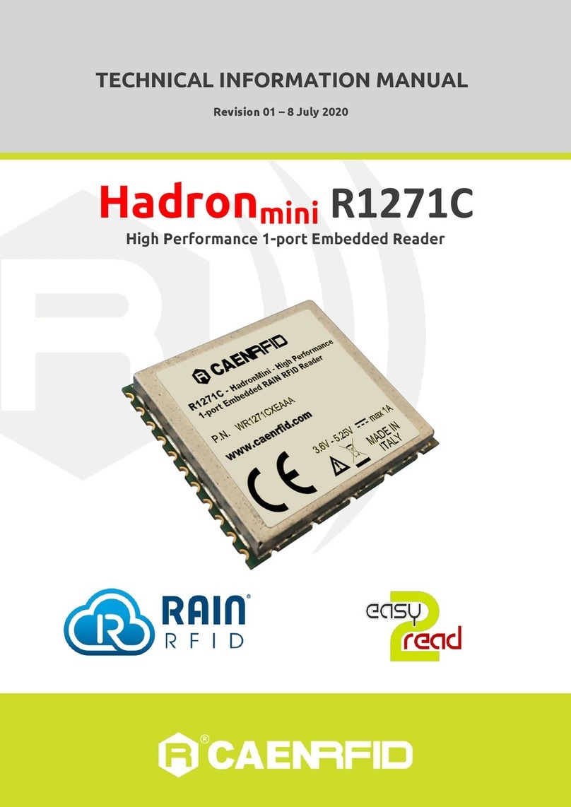
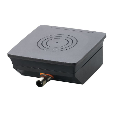
caenrfid Lepton7x1 Technical document

TECHNICAL INFORMATION MANUAL
Revision 0 –21/07/2022
R7101C
Lepton7x1
30dBm 1-Port RAIN RFID
Reader Module
R7104C
Lepton7x4
30dBm 4-Port RAIN RFID
Reader Module

Visit the Lepton7x1 R7101C and Lepton7x4 R7104C web pages,
you will find the latest revision of data sheets, manuals,
certifications, technical drawings, software and firmware.
All you need to start using your reader in a few clicks!
Scope of the Manual
The goal of this manual is to provide the basic information to work with the Lepton7x1 R7101C and Lepton7x4
R7104C Readers.
Change Document Record
Date
Revision
Changes
Pages
21/07/2022
00
Preliminary revision
-
Reference Document
[RD1] EPCglobal: EPC Radio-Frequency Identity Protocols Class-1 Generation-2 UHF RFID Protocol for
Communications at 860 MHz –960 MHz, Version 2.0.1 (April 2015).
CAEN RFID srl
Via Vetraia, 11 55049 Viareggio (LU) - ITALY
Tel. +39.0584.388.398 Fax +39.0584.388.959
info@caenrfid.com
www.caenrfid.com
© CAEN RFID srl –2022
Disclaimer
No part of this manual may be reproduced in any form or by any means, electronic, mechanical, recording, or
otherwise, without the prior written permission of CAEN RFID.
The information contained herein has been carefully checked and is believed to be accurate; however, no
responsibility is assumed for inaccuracies. CAEN RFID reserves the right to modify its products specifications
without giving any notice; for up to date information please visit www.caenrfid.com.
Preliminary Product Information
This document contains information for a new product. CAEN RFID reserves the right to modify this product
without notice.
“Preliminary” product information describes products that are ready for production, but for which full
characterization data is not yet available. CAEN RFID believes that the information contained in this document
is accurate and reliable. However, the information is subject to change without notice and is provided “AS IS”
without warranty of any kind (Express or implied). You are advised to obtain the latest version of relevant
information to verify, before placing orders, that information being relied on is current and complete. All
products are sold subject to the terms and conditions of sale supplied at the time of order acknowledgement,
including those pertaining to warranty, patent infringement, and limitation of liability. No responsibility is
assumed by CAEN RFID for the use of this information, including use of this information as the basis for
manufacture or sale of any items, or for infringement of patents or other rights of third parties.

Disposal of the product
Do not dispose the product in municipal or household waste. Please check your local
regulations for disposal/recycle of electronic products.

INDEX - Lepton7x1 - Lepton7x4 - Technical Information Manual 4
Index
Scope of the Manual .................................................................................................................................................................2
Change Document Record.......................................................................................................................................................2
Reference Document................................................................................................................................................................2
1Introduction.....................................................................................................................................................................6
Description.................................................................................................................................................................................6
Reader ............................................................................................................................................................................6
Evaluation Board ..........................................................................................................................................................8
Ordering Options ......................................................................................................................................................................8
2Technical Specifications ................................................................................................................................................9
Technical Specifications ...........................................................................................................................................................9
Key Features ............................................................................................................................................................................10
3Hardware Interface.......................................................................................................................................................11
Introduction .............................................................................................................................................................................11
Power Supply ...........................................................................................................................................................................12
RF Connection..........................................................................................................................................................................12
UART Communication ............................................................................................................................................................12
Reset Pin...................................................................................................................................................................................13
GPIO Pins ..................................................................................................................................................................................13
Wakeup Pin ..............................................................................................................................................................................14
External Connections and Mechanical Drawings ...............................................................................................................14
Electrical Specifications .........................................................................................................................................................16
Absolute Maximum Ratings......................................................................................................................................16
Operating Conditions ................................................................................................................................................16
Device Functional Specifications .............................................................................................................................16
UHF Gen 2 RFID Radio Specifications......................................................................................................................17
Device Input and Output Specifications .................................................................................................................17
EPC Class-1 Generation-2 Operation ...................................................................................................................................18
Supported RF modes..................................................................................................................................................18
4Evaluation Board...........................................................................................................................................................19
Technical Specifications Table ..............................................................................................................................................19
Connection Diagram ...............................................................................................................................................................19
Installation Notice ......................................................................................................................................................22
Connecting to the R7101C Lepton7x1/R7104C Lepton7x4 reader..................................................................................24
USB Communication Setup .......................................................................................................................................24
Easy Controller............................................................................................................................................................24
Technical Drawings .................................................................................................................................................................27
Electrical Schematic................................................................................................................................................................28
External Connections .............................................................................................................................................................29
Jumpers and Switches............................................................................................................................................................29
LEDs...........................................................................................................................................................................................30
5Regulatory Compliance................................................................................................................................................31
RoHS EU Directive...................................................................................................................................................................31

INDEX - Lepton7x1 - Lepton7x4 - Technical Information Manual 5
List of Figures
Fig. 1.1: Lepton7x1 (Model R7101C) Reader –top view .................................................................................................................6
Fig. 1.2: Lepton7x4 (Model R7104C) Reader –top view .................................................................................................................7
Fig. 1.3: Evaluation Board for Lepton7x1 and Lepton7x4 readers ................................................................................................8
Fig. 3.1: Lepton7x1 R7101C/Lepton7x4 R7104C - Example of Block Diagram ..........................................................................11
Fig. 3.2: BSL sequence .......................................................................................................................................................................12
Fig. 3.3: R7101C Lepton7x1 mechanical drawings and connectors locations (units: mm) ......................................................14
Fig. 3.4: R7104C Lepton7x4 mechanical drawings and connector locations (units: mm)........................................................15
Fig. 4.1: Evaluation Board R4320CEVB –R7101C Reader Connection Diagram.......................................................................19
Fig. 4.2: Evaluation Board R4320CEVB –R7104C Reader Connection Diagram.......................................................................20
Fig. 4.3: Evaluation Board R4320CEVB –R7101C Reader Interface Connectors .....................................................................20
Fig. 4.4: Evaluation Board R4320CEVB –R7104C Reader Interface Connectors .....................................................................21
Fig. 4.5: Connection of the R7101C module to the R4320CEVB evaluation board .................................................................22
Fig. 4.6: Connection of the R7104C module to the R4320CEVB evaluation board .................................................................23
Fig. 4.7: R4320CEVB Technical Drawing .........................................................................................................................................27
Fig. 4.8: R4320CEVB Electrical Schematic ......................................................................................................................................28
Fig. 4.9: SW2 configuration...............................................................................................................................................................29
Fig. 4.10: SW3 configuration.............................................................................................................................................................30
List of Tables
Tab. 2.1: Lepton7x1 - R7101C Lepton7x4 R7104C Technical Specifications................................................................................9
Tab. 3.1: Power supply and interface connector pin listing and signal definitions..................................................................15
Tab. 3.2: Absolute Maximum Ratings..............................................................................................................................................16
Tab. 3.3: Operating Conditions ........................................................................................................................................................16
Tab. 3.4: Supply Current Specifications ..........................................................................................................................................16
Tab. 3.5: Startup and Wakeup Time.................................................................................................................................................16
Tab. 3.6: RF Receiver Specifications ................................................................................................................................................17
Tab. 3.7: RF Transmitter Specifications ..........................................................................................................................................17
Tab. 3.8: Digital Interface Specification..........................................................................................................................................17
Tab. 3.9: RF Modes –Forward and Reverse Link Profiles.............................................................................................................18
Tab. 3.10: Inventory Performance ...................................................................................................................................................18
Tab. 4.1: R4320CEVB –Lepton7x1 and Lepton7x4 Evaluation Board - Technical Specifications ...........................................19

INTRODUCTION - Lepton7x1 - Lepton7x4 - Technical Information Manual 6
1INTRODUCTION
Description
Reader
The Lepton7x1 (Model R7101C) and Lepton7x4 (Model R7104C), embedded readers of the easy2read©
product line, are ultra compact readers for low power, high performance RAIN RFID applications.
With programmable output power from 10 dBm to 30 dBm, the readers can detect tags at more than 5 m
of distance (depending on antenna and tag dimensions).
Due to their low power consumption, the modules are specifically designed to be easily integrated in
battery powered devices.
The radio frequency core of the modules is based on the Impinj E710 IC that permits to achieve fast reading
speed and to be used in dense reader and dense tag environments for top-class rated performances.
The compactness of the devices allows to embed the Lepton7x1 and Lepton7x4 inside industrial handhelds,
smartphone accessories and other compact form factor devices.
The Lepton7x1 and Lepton7x4 comply with and can operate in both European and US regulatory
environments and, thanks to their multiregional capabilities, they are ideal for integration in devices
requiring compliance to different geographical regions.
The Lepton7x1 and Lepton7x4 are designed on the basis of the Lepton7with the aim to facilitate the
integration for those who prefer to use connectors instead of automatic manufacturing required by the
SMD form factor. In addition, Lepton7x4 is a turnkey solution for systems requiring up to 4 antenna ports.
Fig. 1.1: Lepton7x1 (Model R7101C) Reader –top view

INTRODUCTION - Lepton7x1 - Lepton7x4 - Technical Information Manual 8
Evaluation Board
The Mod. R4320CEVB - Evaluation Board allows managing the Lepton7x1 and Lepton7x4 readers directly
using an USB interface (via the embedded USB to UART converter). This board is particularly suited for
Lepton7x1 and Lepton7x4 readers evaluation and SW development purpose.
For more information, please refer to § Evaluation Board chapter page 19.
Fig. 1.3: Evaluation Board for Lepton7x1 and Lepton7x4 readers
Ordering Options
Code
Description
Reader
WR7101CXAAAA
Lepton7x1 - 30dBm Reader Module
WR7104CXAAAA
Lepton7x4 - 30dBm Reader Module
Accessories
WALIM0000005
Power Supply for R4320CEVB
WR4320CXEVBX
Lepton7x1 and Lepton7x4 - Evaluation Board

TECHNICAL SPECIFICATIONS - Lepton7x1 - Lepton7x4 - Technical Information Manual 9
2TECHNICAL SPECIFICATIONS
Technical Specifications
Frequency Range
865.600÷867.600 MHz (ETSI EN 302 208 v3.3.1)
902÷928 MHz (FCC part 15.247)
RF Power
Configurable from 10 dBm to 30 dBm (from 10 mW to 1 W) conducted
power
RX Sensitivity
-85dBm -10%PER, assuming 20 dB antenna RL @ 30 dBm output
Antenna VSWR
Requirement
< 2:1 for optimum performances
Antenna Connectors
-1 MMCX jack (Model R7101C Lepton7x1)
-4 MMCX jack (Model R7104C Lepton7x4)
Frequency Tolerance
±10ppm over the entire temperature range
Number of Channels
4 channels (compliant to ETSI EN 302 208 v3.3.1)
50 hopping channels (compliant to FCC part 15.247)
Standard Compliance
EPC C1G2 / ISO18000-63
I/O Interface
4 I/O lines 3.3V level
Iout = 8mA max
Connectivity
-UART Serial Port
•Baudrate: from 9.6 to 921.6 kbps, default 921.6 kbps
•Databits: 8
•Stopbits:1
•Parity: none
•Flow control: none
-3.3 V I/O voltage level
Power Supply
3.2 ÷ 5.25 V DC
Power Consumption
-8W max @ RF out = 30 dBm
-80 mW in idle mode –Ready to receive commands
Dimensions
-Model R7101C Lepton7x1:
(L) 51 x (W) 42 x (H) 8.1 mm3
2.01 x 1.65 x 0.32 inches3
-Model R7104C Lepton7x4:
(L) 60 x (W) 42 x (H) 8.1 mm3
2.36 x 1.65 x 0.32 inches3
Operating Temperature
-20°C to +70°C
Weight
−30 g (Model R7101C Lepton7x1)
−34 g (Model R7104C Lepton7x4)
Tab. 2.1: Lepton7x1 - R7101C Lepton7x4 R7104C Technical Specifications
Warning: The RF settings must match the operating country/region to comply with local laws
and regulations.
The usage of the reader in different countries/regions from the one in which the device has
been sold is not allowed.

TECHNICAL SPECIFICATIONS - Lepton7x1 - Lepton7x4 - Technical Information Manual 10
Key Features
•RAIN RFID (UHF EPC Class1 Gen2, ISO 18000-63) compliant
•Both ETSI and FCC support in the same module
•Ultra compact size
•Up to 30 dBm (1W) output power
•-85 dBm Rx sensitivity, assuming 20 dB antenna return loss
•Inventory (FastID, Tag Population Estimate, Select, Session, Target)
•Access (Read, Write, Lock, Kill, BlockPermalock, and QT)
•Shielded to prevent unwanted radiation and provide noise immunity in embedded environments
•Single mono-static RF port
•Field upgradability via firmware updates. Gen 2 v2 will be firmware upgradable
•UART serial interface using CAEN RFID easy2read©protocol
•Test features (CW, PRBS, custom regions, channel lists, and fixed frequency)

HARDWARE INTERFACE - Lepton7x1 - Lepton7x4 - Technical Information Manual 11
3HARDWARE INTERFACE
Introduction
An example R7101C Lepton7x1/R7104C Lepton7x4 system-level block diagram for an embedded system is
shown in Fig. 3.1: Lepton7x1 R7101C/Lepton7x4 R7104C - Example of Block Diagram. This figure shows the
electrical connections that may and must be made to control the R7101C Lepton7x1/R7104C Lepton7x4. In
the figure, the required connections are illustrated with solid lines. Recommended and optional
connections are illustrated with different dotted and dashed line patterns. More details for each
connection are listed in the following paragraphs.
Fig. 3.1: Lepton7x1 R7101C/Lepton7x4 R7104C - Example of Block Diagram
Required connections:
•VDC_IN and GND are required to power the R7101C Lepton7x1/R7104C Lepton7x4.
•RF is required to connect to the UHF RFID antenna.
•UART1 Tx and Rx are required to communicate with the system host.
Recommended connections:
•nRST is used to reset the R7101C Lepton7x1/R7104C Lepton7x4 if UART communication is not
available. This connection is highly recommended. This pin is internally driven strong low during
software resets, so it should only be driven externally by an open drain signal. It must not be driven
strong high.
•TST and BSL_SEL shall be used for the FW recovery/upgrade procedure.
In order to start the Boot Strap Loader of Lepton7 internal microcontroller NRST, TST and BSL_SEL
signals shall be driven as in the picture below:

HARDWARE INTERFACE - Lepton7x1 - Lepton7x4 - Technical Information Manual 12
Fig. 3.2: BSL sequence
The BSL program execution starts when TST pin has received a minimum of two positive transitions
and if TST is high while /RST rises from low to high. BSL_SEL shall be at high level before BSL starts.
Pulses length and distance between edges of all signals shall be 10ms at least.
Optional connections:
•GPIOs allow interaction with the R7101C Lepton7x1/R7104C Lepton7x4 as both digital inputs and
outputs. They may be used to trigger inventory, generate events based on inventory activity, or
provide general-purpose user-controlled digital I/O.
•WKUP provides a mechanism to wake up the R7101C Lepton7x1/R7104C Lepton7x4 from the low
power Sleep mode. If unused, this pin should be tied to logic low.
Power Supply
The R7101C Lepton7x1/R7104C Lepton7x4 is powered by a voltage applied to the VDC_IN pin (pin 3 and 4)
relative to the GND pins. The supply voltage operating range is 3.2V to 5.25V. Power consumption varies
from about 8W to about 80mW depending on the operating mode. The power supply is internally bypassed
and regulated, and no external bypass or bulk storage capacitance is required, as long as the input voltage
is stable.
If R7101C Lepton7x1/R7104C Lepton7x4 activity is not required at all times, and power reduction is desired,
the VDC_IN supply voltage may be externally gated to remove power to the device.
RF Connection
The Lepton7x1 R7101C has a single MMCX jack RF port, the Lepton7x4 R7104C has four MMCX jacks RF
ports. Each RF port shall be connected to a 50 Ω antenna via a MMCX plug and 50 Ω cable.
UART Communication
The R7101C Lepton7x1/R7104C Lepton7x4 has one full-duplex UART standard interface, accessible using
pins UART-RX, UART-TX. Such UART implements the host communication interface via easy2read©. The Tx
pin is output from the R7101C Lepton7x1/R7104C Lepton7x4, the Rx pin is input to the R7101C
Lepton7x1/R7104C Lepton7x4. Interface settings are by default 921,600 baud, with 8 data bits, 1 stop bit,
and no parity bit (8-n-1 configuration).
UART interface signals are 3.3 V relative to GND. The specific VIH, VIL, VOH and VOL specifications may be
found in the § Device Input and Output Specifications paragraph page 17. The TX pin is driven strong high
and low with a sink/source current of about 8 mA. If the load on a pin draws more than the 8 mA sink and
source current, the pin is not guaranteed to meet the VOH and VOL specs listed in § Device Input and
Output Specifications paragraph page 17. Excessive current sunk or sourced on the GPIO pins can also cause
electrical damage to the device.
Warning: Voltages outside of the maximum IO operating voltage range of -0.3 to 4.0 V should
not be applied to the UART pins. This can cause permanent damage to the device.

HARDWARE INTERFACE - Lepton7x1 - Lepton7x4 - Technical Information Manual 13
Reset Pin
The R7101C Lepton7x1/R7104C Lepton7x4 may be reset by a logic low voltage on the NRST pin (pin 14).
Usage of this pin is recommended in all designs. It may be used to reset the part if an unexpected
operating state is entered. The R7101C Lepton7x1/R7104C Lepton7x4 does have an internal watchdog
circuit that will reset it if abnormal operation occurs, but the NRST pin provides a further level of reliability.
The NRST pin is pulled high (3.3 V) by an internal 51,1 kΩ nominal resistor. To reset the part, drive the pin
strong low for at least the minimum reset pulse width as specified in § Device Input and Output
Specifications paragraph page 17 (approximately 25 μs). This pin may be driven active low to reset the part,
but should not be driven strong high. Driving the pin strong high prevents the R7101C Lepton7x1/R7104C
Lepton7x4 from resetting itself in case user requested software reset. This pin should be driven using an
“open drain drives low” drive mode, which creates either a strong low voltage or a floating voltage output.
GPIO Pins
The R7101C Lepton7x1/R7104C Lepton7x4 GPIOs can be controlled using the easy2read©interface. Their
drive mode, direction, and state are all controllable via easy2read©. There are two directions: input and
output. In both input and output directions, there are three possible pin states: high, low, and float. For
more details on using easy2read©to control the GPIOs, see the easy2read©protocol documentation.
In the output direction, the GPIOs are driven strong high and low with a source and sink current of 8 mA,
and in float mode the pin is not driven either high or low, leaving the pin floating, also known as “high
impedance” or “high-Z”. The pins are driven to 3.3 V nominally. If the load on a pin draws more than the 8
mA sink and source current, the pin is not guaranteed to meet the VOH and VOL specs listed in the § Device
Input and Output Specifications paragraph page 17.
Warning: Excessive current sunk or sourced on the GPIO pins can also cause electrical damage
to the device.
In the input direction, the high and low states apply a pull-up or pull-down resistor, and in float mode the
pin is not pulled either high or low, leaving the pin floating, also known as “high impedance” or “high-Z”.
The pull-up and pull-down resistors are about 35 kΩ nominal. See the § Device Input and Output
Specifications paragraph page 17 for more specific ratings. The inputs logic levels are proportional to 3.3 V.
Specific VIH and VIL specs may be found in the § Device Input and Output Specifications paragraph page 17.
Warning: Voltages outside of the maximum IO operating voltage range of -0.3 to 4.0 V should
not be applied to the pins, no matter their configuration. This can cause permanent damage to
the device.

HARDWARE INTERFACE - Lepton7x1 - Lepton7x4 - Technical Information Manual 14
Wakeup Pin
The WKUP pin is used to wake the device when it is in the Standby or Sleep operating modes. This pin is
edge sensitive and will wake the device on a rising edge. The WKUP pin must be logic low in order for the
device to re-enter Idle mode after a Sleep wakeup, so it should only be pulsed high to wake up the part.
The WKUP pin operates at a 3.3 V logic level. It has a 35 kΩ typical pull-down resistor inside the R7101C
Lepton7x1/R7104C Lepton7x4. Voltages outside of the maximum IO operating voltage range of -0.3 to 4.0
V should not be applied to the WKUP pin. This can cause permanent damage to the device.
If the WKUP pin is not used, it should be left floating or tied to logic low (ground).
External Connections and Mechanical Drawings
The location of the connectors is shown in Fig. 3.3: R7101C Lepton7x1 mechanical drawings and connectors
locations (units: mm) and Fig. 3.4: R7104C Lepton7x4 mechanical drawings and connector locations (units: mm).
Their part numbers are listed here below:
Antenna Ports: RF Coax Connector Huber+Suhner type 82_MMCX-S50-0-2/111_K (to be used with
Huber+Suhner type 11_MMCX-50-1-1/111_O)
MOLEX Connector: PCB Header Molex type 53261-1571 (to be used with Molex Type 51021-1500 + 15pcs
crimp terminal type 50058-8100)
Fig. 3.3: R7101C Lepton7x1 mechanical drawings and connectors locations (units: mm)

HARDWARE INTERFACE - Lepton7x1 - Lepton7x4 - Technical Information Manual 15
Fig. 3.4: R7104C Lepton7x4 mechanical drawings and connector locations (units: mm)
Pin #
Name
Direction
Function
1
GND
-
Ground
2
GND
-
Ground
3
VDC_IN
-
Supply voltage
4
VDC_IN
-
Supply voltage
5
GPIO0
IN/OUT
General purpose I/O #0
6
GPIO1
IN/OUT
General purpose I/O #1
7
GPIO2
IN/OUT
General purpose I/O #2
8
GPIO3
IN/OUT
General purpose I/O #3
9
RXD
IN
UART RX (input to the module)
10
TXD
OUT
UART TX (output from the
module)
11
WKUP
IN/OUT
Wakeup from sleep on rising
edge
12
STATUS
IN/OUT
R7101C Lepton7x1 / R7104C
Lepton7x4 status indication
13
TST
IN
TST pin to be used for FW
recovery/upgrade
14
nRST
IN
Active low reset. Connect to open
drain driver.
15
BSL_SEL
IN
Boot Strap Loader interface
enable signal
Tab. 3.1: Power supply and interface connector pin listing and signal definitions

HARDWARE INTERFACE - Lepton7x1 - Lepton7x4 - Technical Information Manual 16
Electrical Specifications
Absolute Maximum Ratings
The absolute maximum ratings (see Tab. 3.2: Absolute Maximum Ratings) define limitations for electrical
and thermal stresses. These limits prevent permanent damage to the R7101C Lepton7x1/R7104C
Lepton7x4.
Operation outside maximum ratings may result in permanent damage to the device.
Parameter
Min.
Max.
Unit
Conditions
Supply voltage
-0.3
5.5
V
VDC_IN pin relative to GND
IO voltage
-0.3
4.0
V
Non-VDC_IN pin voltages relative to GND
RF input power
-
+30
dBm
Incident to pin 1 (RF)
Storage temperature
-30
+100
ºC
Humidity
-
95
% RH
Non-condensing
ESD immunity
-
2
kV
Human-body model, all I/O pads
Tab. 3.2: Absolute Maximum Ratings
Operating Conditions
This section describes operating voltage, frequency, and temperature specifications for the R7101C
Lepton7x1/R7104C Lepton7x4 during operation.
Parameter
Min.
Max.
Unit
Conditions
Supply
3.2
5.25
V
VDC_IN relative to GND
Temperature
-20
+70
ºC
Ambient Temperature
Frequency
902
928
MHz
FCC part 15.247
865.6
867.6
MHz
ETSI EN 302 208 v3.3.1
Tab. 3.3: Operating Conditions
Device Functional Specifications
This section describes operating voltage, frequency, and temperature specifications for the R7101C
Lepton7x1/R7104C Lepton7x4 during operation.
Parameter
Typ.
Unit
Description
Supply Current
Current consumed by Lepton7R7100C via VDC_IN
pin
Active mode - 5V supply
8
W
+30 dBm transmit power
Inventorying tags
Idle mode –low latency
300
mW
Ready to receive easy2read©protocol packets.
Lower latency to return to Active mode.
Idle mode –standard latency
80
mW
Ready to receive easy2read©packets
Standby mode
TBD
mA
GPIO activity or WKUP rising edge required to
wakeup part.
Sleep mode
TBD
μA
WKUP rising edge required to wakeup part.
Tab. 3.4: Supply Current Specifications
Parameter
Min.
Typ.
Max.
Unit
Description
Startup Time
TBD
ms
Time to receive easy2read©packets after power
supply or nRST pin initiated startup
Wakeup Time
Time to receive packets after wakeup event
Standby
TBD
ms
GPIO activity or WKUP rising edge required to
wakeup part.
Sleep
TBD
ms
WKUP rising edge required to wakeup part.
Tab. 3.5: Startup and Wakeup Time

HARDWARE INTERFACE - Lepton7x1 - Lepton7x4 - Technical Information Manual 17
UHF Gen 2 RFID Radio Specifications
Parameter
Min.
Typ.
Max.
Unit
Conditions
Frequency
902
928
MHz
See § Tab. 2.1: Lepton7x1 - R7101C Lepton7x4
R7104C Technical Specifications page 9
865.6
867.6
MHz
Input impedance
50
Ω
Input match
-10
dB
S11
Rx sensitivity
-85
dBm
10%PER, assuming 20 dB antenna RL @ 30 dBm
output
Tab. 3.6: RF Receiver Specifications
Parameter
Min.
Max.
Unit
Notes
Tx Power
10
30
dBm
Meets FCC and equivalent regulatory
constraints
Tx Power Error
1
dB
Difference between desired Tx power and
actual Tx power
Return Loss
0
dB
No damage into open RF port at 30 dBm
at any phase angle
Frequency
865.6
867.6
MHz
ETSI EN 302 208 v3.3.1
902
928
MHz
FCC part 15.247
Tab. 3.7: RF Transmitter Specifications
Device Input and Output Specifications
Parameter
Min.
Typ.
Max.
Unit
Conditions
nRST
VIL
-0.3
0.8
V
VIH
2
3.6
V
Hysteresis voltage
400
mV
Internal pull-up resistor
14
21
25
kΩ
Reset pulse width
25
μs
WKUP
VIL
-0.3
0.8
V
VIH
2
3.6
V
Hysteresis voltage
400
mV
Internal pull-down resistor
20
35
50
kΩ
Digital inputs
VIL
-0.3
0.8
V
VIH
2
3.6
V
Hysteresis voltage
400
mV
Internal pull-down resistor
20
35
50
kΩ
Digital outputs
VOL
0.0
0.6
V
VOH
2.7
3.6
V
Drive current (sink or source)
8
mA
UART
Default baud rate
921.6
kbaud
Configurable baud rate
9.6
921.6
kbaud
Data bits
8
bits
Parity bit
None
Stop bits
1
bits
Tab. 3.8: Digital Interface Specification

HARDWARE INTERFACE - Lepton7x1 - Lepton7x4 - Technical Information Manual 18
EPC Class-1 Generation-2 Operation
Supported RF modes
The R7101C Lepton7x1/R7104C Lepton7x4 supports the following link profiles, whose characteristics are
reported in the following table:
Link Profile
Regulation
Forward Link Profile
Reverse Link Profile
R2T Modulation
Tari
PIE
T2R Modulation
Link Frequency
1
ETSI
PR-ASK
20 μs
2
Miller M=2
320 kHz
2
ETSI
PR-ASK
20 μs
2
Miller M=4
320 kHz
3
FCC
PR-ASK
20 μs
2
Miller M=4
250 kHz
4
ETSI
PR-ASK
15 μs
2
Miller M=2
320 kHz
5
ETSI/FCC
PR-ASK
20 μs
2
Miller M=8
160 kHz
6
FCC
PR-ASK
7.5 μs
2
FM0
640 kHz
7
FCC
PR-ASK
7.5 μs
2
Miller M=2
640 kHz
8
FCC
PR-ASK
7.5 μs
2
Miller M=4
640 kHz
9
FCC
DSB-ASK
6.25 μs
2
FM0
640 kHz
10
FCC
DSB-ASK
6.25 μs
2
Miller M=2
640 kHz
Tab. 3.9: RF Modes –Forward and Reverse Link Profiles
In the following table are reported the inventory performances that can be achieved with Link Profile 2 and
Link Profile 3:
Parameter
Min.
Typ.
Max.
Unit
Conditions
Inventory Rate
(Link profile 2)
TBD
Tags/sec
1 Tag with tag population estimate = 0 (Q=0)
TBD
Tags/sec
20 Tags with tag population estimate = 16
TBD
Tags/sec
100 Tags with tag population estimate = 128
Inventory Rate
(Link profile 3)
TBD
Tags/sec
1 Tag with tag population estimate = 0 (Q=0)
TBD
Tags/sec
20 Tags with tag population estimate = 16
TBD
Tags/sec
100 Tags with tag population estimate = 128
Tab. 3.10: Inventory Performance

EVALUATION BOARD - Lepton7x1 - Lepton7x4 - Technical Information Manual 19
4EVALUATION BOARD
Technical Specifications Table
Digital I/O
Four I/O lines 3.3 V out @ 3mA, 5 V tolerant
UART via USB Port
USB micro female connector
Baudrate: 921600
Databits: 8
Stopbits: 1
Parity: none
Flow control: none
9.6÷921.6 kbit/s data rate (settable)
It appears as USB serial port; drivers for all Windows OS
LED display
GREEN: power from AC/DC adapter
GREEN: USB connection
YELLOW: UART to USB interface activity
GREEN: GPIO[0..3]
Dimensions
(W)81 x (L)76 x (H)28 mm3
(3.2 x 3.0 x 1.1 inch3)
Electrical Power
DC Voltage 5V +/-5%
Current consumption: 2A max.
Operating
Temperature
-20 °C to +70°C
Tab. 4.1: R4320CEVB –Lepton7x1 and Lepton7x4 Evaluation Board - Technical Specifications
Connection Diagram
The following block diagram shows how to connect the R7101C Lepton7x1/R7104C Lepton7x4 with the PC
host via the R4320CEVB service board.
In the evaluation board R7101C Lepton7x1/R7104C Lepton7x4 UART interface is accessible via an FTDI
UART to USB converter.
The board equipped with R7101C Lepton7x1/R7104C Lepton7x4 readers shall be powered by an external
5V 1A min. DC adapter. The use of the Power Supply for R4320CEVB (WALIM0000005) is recommended
(see § Ordering Options page 8).
Fig. 4.1: Evaluation Board R4320CEVB –R7101C Reader Connection Diagram
This manual suits for next models
3
Table of contents
Other caenrfid RFID System manuals

caenrfid
caenrfid Hex R1290I Technical document

caenrfid
caenrfid easy2read Slate R1260I Technical document

caenrfid
caenrfid Tile R1250I Technical document

caenrfid
caenrfid Lepton9 R9100C Technical document

caenrfid
caenrfid easy2read Slate R1260I Technical document

caenrfid
caenrfid Hardon mini R1271C Technical document

caenrfid
caenrfid R1280I Technical document

caenrfid
caenrfid R1280I Technical document

caenrfid
caenrfid Hadron R4320C Technical document

caenrfid
caenrfid Slate R1260U Technical document